Table of Contents
Advertisement
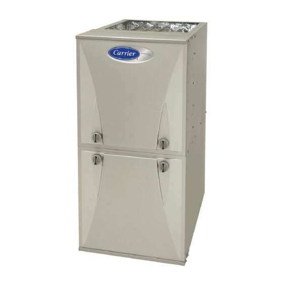
59SP2A
Single Stage, 4---Way Multipoise
Condensing Gas Furnace
Series 1
Installation, Start---up, Operating and
Service and Maintenance Instructions
NOTE: Read the entire instruction manual before starting the installation.
SECTIONS
INTRODUCTION
. . . . . . . . . . . . . . . . . . . . . . . . . . . . . . . . . . .
ACCESSORIES
. . . . . . . . . . . . . . . . . . . . . . . . . . . . . . . . . . . . .
LOCATION
. . . . . . . . . . . . . . . . . . . . . . . . . . . . . . . . . . . . . . . .
. . . . . . . . . . . . . . . . . . . . . . . . . . . . . . .
. . . . . . . . . . . . . . . . . . . . . . . . . . . . .
INSTALLATION
. . . . . . . . . . . . . . . . . . . . . . . . . . . . . . . . . . .
. . . . . . . . . . . . . . . . . . . . . . . . . . . . . . . . . . . . . . .
. . . . . . . . . . . . . . . . . . . . . . . . . . . . . . . . . . . . . .
VENTING
. . . . . . . . . . . . . . . . . . . . . . . . . . . . . . . . . . . . . . . .
PARTS REPLACEMENT GUIDE
Use of the AHRI Certified
Mark indicates a
TM
manufacturer's participation in the program. For
verification of certification for individual products,
go to www.ahridirectory.org.
Portions of the text and tables are reprinted from current edition of
NFPA 54/ANSI Z223.1, with permission of National Fire
Protection Association, Quincy, MA 02269 and American Gas
Association, Washington DC 20001. This reprinted material is not
the complete and official position of the NFPA or ANSI on the
referenced subject, which is represented only by the standard in its
. . . . . . . . . . . . . . . . . . . . . . . . .
. . . . . . . . . . . . . . . . . . . . . . . . . . .
. . . . . . . . . .
. . . . . . . . . . . . . . . . . . . . . . .
. . . . . .
. . . . . . . .
. . . . . . . . . . . . . . . . . . . . . . . .
. . . . . . . . . . . . . . . . . . . . . .
CERTIFIED
entirety.
3
4
4
. . .
5
5
8
Filter Size Information
9
Opening Dimensions
12
Air Delivery CFM
16
. . . . . . . . . . . . . . . . . . . . . . . . . . . . . . . . . . . . . .
20
30
Hangar Spacing
. . . . . . . . . . . . . . . . . . . . . . . . . . . . . . . . . . . . .
32
Combustion- -Air Vent Pipe, Fitting & Cement Material..
33
Maximum Allowable Exposed Vent Lengths Insulation
40
64
73
Blower Off Delay Setup Switch
81
. . . . . . . . . . . . . . . . . . . . . . . . . . . . . . . . . . . . . . . . . .
86
1
TABLES
. . . . . . . . . . . . . . . . . . . . . . . . . . . . . . . . . . . . .
. . . . . . . . . . . . . . . . . . . . . . . . .
. . . . . . . . . . . . . . . . . . . . . . . . . . . . .
. . . . . . . . . . . . . . . . . . . . . . . . . . . . . . .
. . . . . . . . . . . . . . . . . . . . . . . . . . . . . . . .
. . . . . . . . . . . . . . . . . . . . . . . . . . . . . . . . . . .
. . . . . . . . . . . . . . . . . . . . . . . . . . .
. . . . . . . . . . . . . . . . . . . . . .
. . . . . . . . . . . . . . . . . . . . . . . .
. . . . . . . . . . . . . . . . . . . .
. . . . . . . . . . . . . . . . . . . . .
5
. . . . . . . . . . . . .
5
11
11
23
26
31
33
36
. . . . . . .
42
46
. . . . .
48
. . . . . .
49
50
. . . . . . . .
50
67
68
70
71
Advertisement
Table of Contents

Related Manuals for Carrier 59SP2A


Summary of Contents for Carrier 59SP2A
-
Page 1: Table Of Contents
59SP2A Single Stage, 4---Way Multipoise Condensing Gas Furnace Series 1 Installation, Start---up, Operating and Service and Maintenance Instructions NOTE: Read the entire instruction manual before starting the installation. SECTIONS entirety. SAFETY CONSIDERATIONS ...... - Page 2 Required Notice for Massachusetts Installations IMPORTANT The Commonwealth of Massachusetts requires compliance with regulation 248 CMR as follows: 5.08: Modifications to NFPA- -54, Chapter 10 2) Revise 10.8.3 by adding the following additional requirements: a. For all side wall horizontally vented gas fueled equipment installed in every dwelling, building or structure used in whole or in part for residential purposes, including those owned or operated by the Commonwealth and where the side wall exhaust vent termination is less than seven (7) feet above finished grade in the area of the venting, including but not limited to decks and porches, the following requirements shall be satisfied:...
-
Page 3: Safety Considerations
SAFETY CONSIDERATIONS Installing and servicing heating equipment can be hazardous due to gas and electrical components. Only trained and qualified personnel should install, repair, or service heating equipment. WARNING Untrained personnel can perform basic maintenance functions such as cleaning and replacing air filters. All other operations must be FIRE, EXPLOSION, ELECTRICAL SHOCK, AND performed by trained service personnel. -
Page 4: Codes And Standards
8. A gas- -fired furnace for installation in a residential garage furnace model size capacity increments. None of the furnace must be installed as specified in the warning box in the model sizes can be used if the heating load is 20,000 BTU or “Location”... -
Page 5: Electrostatic Discharge (Esd) Precautions
S This product must be installed by a licensed plumber or gas fitter. 1. Disconnect all power to the furnace. Multiple disconnects may be required. DO NOT TOUCH THE CONTROL S When flexible connectors are used, the maximum length shall OR ANY WIRE CONNECTED TO THE CONTROL not exceed 36 in. - Page 6 A180203 59SP2 SHIP WT. LB (KG) FURNACE SIZE CABINET WIDTH OUTLET WIDTH BOTTOM INLET WIDTH AIR INTAKE 040--- 10 112.0 (50.8) 14--- 3/16 (361) 12--- 1/2 (319) 12--- 9/16 (322) 7--- 1/8 (181) 060--- 12 122.5 (55.6) 040--- 12 122.0 (55.3) 060--- 14 17--- 1/2 (445) 15--- 7/8 (403)
- Page 7 THE BLOWER IS LOCATED BELOW THE BURNER SECTION, AND CONDITIONED AIR IS DISCHARGED UPWARD. THE BLOWER IS LOCATED TO THE RIGHT OF THE BURNER SECTION, AND CONDITIONED AIR IS DISCHARGED TO THE LEFT. THE BLOWER IS THE BLOWER IS LOCATED TO THE LEFT LOCATED ABOVE THE OF THE BURNER SECTION, BURNER SECTION, AND...
- Page 8 LOCATION WARNING CAUTION CARBON MONOXIDE POISONING / COMPONENT DAMAGE HAZARD PERSONAL INJURY AND/OR PROPERTY Failure to follow this warning could result in personal injury DAMAGE HAZARD or death and unit component damage. Improper use or installation of this furnace may result in Corrosive or contaminated air may cause failure of parts premature furnace component failure.
-
Page 9: Air For Combustion And Ventilation
Follow the guidelines below to insure that the roof or crawlspace WARNING walls have sufficient free area to provide sufficient air for combustion and ventilation for the furnaces. The guidelines below can be used to insure that other gas appliances have sufficient air FIRE HAZARD for combustion. - Page 10 c. TWO HORIZONTAL DUCTS require 1 sq. in. (645 sq. = 15ft mm) of free area per 2,000 Btuh (1,100 mm /kW) of com- Volume 1000 Btu/hr bined input for all gas appliances in the space per Fig. 6 and Table 3.
-
Page 11: Minimum Free Area Required
Table 3 – Minimum Free Area Required for Each Combustion Air Opening or Duct to Outdoors TWO OPENINGS OR TWO HORIZONTAL DUCTS SINGLE DUCT OR OPENING VERTICAL DUCTS (1 SQ. IN./2,000 BTUH) (1 SQ. IN./3,000 BTUH) (1 SQ. IN./4,000 BTUH) (1,100 SQ. -
Page 12: Condensate Trap
CONDENSATE TRAP NOTICE Condensate Trap - - Upflow Orientation When the furnace is installed in the upflow position, it is not The field- -supplied, accessory horizontal drain trap grommet is necessary to relocate the condensate trap or associated tubing. ONLY REQUIRED FOR DIRECT VENT APPLICATIONS. Refer to Fig. - Page 13 Remove pressure switch tube from front pressure switch and discard. A new tube is shipped in the loose parts bag. Remove relief tube from relief Remove tube from relief port. port on condensate trap. Remove the screw that secures the trap to the collector box and remove trap.
- Page 14 Remove plug from If alternate vent position collector box. is required, loosen clamp DO NOT DISCARD. on inlet of vent elbow. Remove the screw that secures the trap to the collector box and remove trap. Unconverted Factory Configuration As Viewed in the Horizontal Right Orientation NOTE: Remove knockout in casing before re installing the condensate trap.
- Page 15 Remove the screw that secures the condensate trap to the collector box and remove trap. If alternate vent position is required, loosen clamp on vent elbow inlet. Remove relief tube from relief port on condensate trap. Remove front pressure switch tube and discard. A new tube is shipped in the Loose Parts bag.
-
Page 16: Condensate Drain
CONDENSATE DRAIN CONNECTION c. All condensate piping is at least 3/4-in. PVC and there is a relief tee at the top of condensate drain piping as shown CAUTION in Fig. 14. NOTE: On narrower casings, it may be easier to remove the condensate trap, connect the drain line components and re-install FROZEN AND BURST WATER PIPE HAZARD the condensate trap. - Page 17 6. From the outside of the casing, insert the angled end of the 2. To allow for servicing the trap, the condensate drain elbow Z-pipe through drain hole in the left side of the casing and in the loose parts bag can be used to make a coupler to behind the inducer or gas valve.
- Page 18 Evaporator Coil + + + + = Positive pressure < + = Pressure lower than areas with + − = Negative pressure Condensing Furnace Blower creates positive pressure. Positive pressure extends into coil condensate drain (no trap). < + < + <...
- Page 19 Ä Ä Ä Ä Ä Ä Ä Ä Ä Ä Evaporator Coil + + + Ä Ä Ä Ä Ä Ä Ä Ä Ä Ä Ä Ä Ä Ä Ä Ä Ä Ä Ä Ä 3/4” PVC Ä Ä Ä Ä Ä Ä Ä Ä Ä Ä Ä...
- Page 20 INSTALL CLAMPS ON DRAIN TUBE ATTACH ELBOW TO ATTACH DRAIN TUBE TO CONDENSATE FORMED END CONDENSATE TRAP DRAIN TRAP OF GROMMET CUT FORMED END OFF PULL DRAIN STUB CONDENSATE DRAIN THROUGH CASING ELBOW CONNECT SHORT END OF ’Z’ PIPE TO MODIFIED DRAIN ELBOW FACTORY SUPPLIED 1/2 IN.
- Page 21 Supply Air Connections Downflow Installation For a furnace not equipped with a cooling coil, the outlet duct shall NOTE: The furnace must be pitched as shown in Fig. 25 for be provided with a removable access panel. This opening shall be proper condensate drainage.
- Page 22 Horizontal Installation accessories MUST be connected to duct external to furnace main casing. NOTE: The furnace must be pitched forward as shown in Fig. 25 Return Air Connections for proper condensate drainage. CAUTION WARNING FURNACE RELIABILITY HAZARD FIRE, EXPLOSION, AND CARBON MONOXIDE POISONING HAZARD Failure to follow this caution may result in unit component damage.
- Page 23 openings are used in Fig. 28, each opening used will require an best blower electrical efficiency and system airflow performance optional filter. occurring with filter pressure drops under 0.1 in. W.C. (25 Pa). The optional media cabinet (or field supplied accessory air cleaner) NOTICE can also be installed in the common return duct prior to entering the return air opening in any orientation.
- Page 24 Table 6 – Filter Media Pressure Drop (Clean) Versus Face Velocity- - In. W.C. (Pa) Representative After-Market Filter Media* Factory-Accessory Face Velocity Washable Fiberglass* Pleated* (m/s) (1-in. / 2.5 cm) (1-in. / 2.5 cm) (2-in. / 5 cm) (1-in. / 2.5 cm) (2-in.
- Page 25 4-in. 21-in. Furnace Block Off 14-3/16 and 17-1/2-in. Plate Furnace 4-Ton or less, AC capacity airflow 1/2-in. Screws 20-in. Media Cabinet 16-in. Media Cabinet Media Cabinet Installation Media Cabinet Installation Option for Side Return 4-Ton or Less A/C Capacity 21- or 24-1/2-in. 21-in.
- Page 26 FURNACE FURNACE (OR COIL CASING WHEN USED) APPROVED COIL ASSEMBLY COIL BOX COMBUSTIBLE COMBUSTIBLE FLOORING FLOORING PLENUM OPENING DOWNFLOW SUBBASE SHEET METAL PLENUM FLOOR SHEET METAL PLENUM OPENING FLOOR FLOOR OPENING OPENING A10491 Fig. 20 - - Installation on Combustible Flooring Table 8 –...
- Page 27 UPFLOW DOWNFLOW HORIZONTAL PERFORATED DISCHARGE DUCT 90° 90° FLANGE 120° 120° 120° A10493 Fig. 21 - - Duct Flanges BOTTOM CLOSURE SCREWS (2) Representative drawing only, SCREWS (4) some models may vary in appearance. Lay furnace on the back or side BOTTOM PLATE Remove the two (2) screws that secure the bottom...
- Page 28 Fig. 25 - - Furnace Pitch Requirements A13109 Fig. 28 - - Horizontal Return Air Configurations and Restrictions Model 59SP2A Only ANY COMBINATION OF 1, 2, OR 3 PERMITTED. A11036 Fig. 26 - - Upflow Return Air Configurations and Restrictions...
- Page 29 COMBUSTION - AIR PIPE (SEE VENTING SECTION) 30 IN. (762 mm) MIN. WORK AREA 2-IN. (51 mm) ROLLOUT PROTECTION REQUIRED Install 12” x 22” (305x559 mm) sheet metal in front of burner compartment area. The sheet metal MUST extend underneath the furnace casing by 1-in. (25 mm) with the door removed.
-
Page 30: Air Ducts
AIR DUCTS NOTICE Many states, provinces and localities are considering or have implemented standards and/or restrictions on duct sizing practices, ductwork leakage, and/or ductwork thermal, airflow and electrical efficiencies. CONSULT LOCAL CODE OFFICIALS ductwork design performance requirements in your area. General Requirements The duct system should be designed and sized according to accepted national standards such as those published by: Air... - Page 31 Table 9 – Air Delivery - - CFM (With Filter) EXTERNAL STATIC PRESSURE (IN.W.C.) RETURN-AIR SPEED UNIT SIZE 2, 3 CONNECTION TAPS Gray 1025 Yellow 040---10 SIDE/BOTTOM Orange Blue Gray 1165 1130 1095 1060 1025 Yellow 040---12 SIDE/BOTTOM Blue Orange Gray 1165 1140...
-
Page 32: Gas Piping
GAS PIPING WARNING WARNING FIRE OR EXPLOSION HAZARD A failure to follow this warning could result in personal FIRE OR EXPLOSION HAZARD injury, death, and/or property damage. Failure to follow this warning could result in personal If local codes allow the use of a flexible gas appliance injury, death, and/or property damage. -
Page 33: Electrical Connections
ELECTRICAL CONNECTIONS Table 10 – Maximum Capacity of Pipe NOMINAL LENGTH OF PIPE --- FT (M) IRON PIPE WARNING SIZE (3.0) (6.0) (9.1) (12.1) (15.2) IN. (MM) 1/2 (13) ELECTRICAL SHOCK, FIRE OR EXPLOSION 3/4 (19) HAZARD 1 ( 25) Failure to follow safety warnings could result in 1-1/4 (32) 1400... - Page 34 bracket grounding screw. If the J- -Box cover is not used, the field CAUTION and factory spliced connections must be located inside the external electrical box. Do not leave splice connections unprotected inside the furnace. FURNACE MAY NOT OPERATE HAZARD The J- -Box cover, mounting bracket and screws are shipped in the Failure to follow this caution may result in intermittent loose parts bag included with the furnace.
- Page 35 5. Pull furnace line voltage power wires through strain- -relief NOTE: Use AWG No. 18 color-coded copper thermostat wire for bushing of the external electrical box. lengths up to 100 ft. (31 M). For wire lengths over 100 ft., use AWG No.
-
Page 36: Electrical Data
Table 11 – Electrical Data MINIMUM MAXIMUM MAXIMUM OPERATING VOLTAGE VOLTS--- MAXIMUM UNIT WIRE WIRE FUSE OR CKT RANGE* HERTZ--- UNIT UNIT SIZE AMPACITY# SIZE LENGTH PHASE AMPS Maximum* Minimum* FT (M)} AMPS{ 040---10 115--- 60--- 1 38 (11.6) 040---12 115--- 60--- 1 38 (11.6) 060---12... - Page 37 To HUM Terminal On To Humidifier Leads Furnace Control Board 24 V Coil To Humidifier Leads To Com/24V Screw Terminal on Thermostat Strip A11157 Fig. 36 - - Field- -supplied Isolation Relay for Humidifiers with Internal Power Supply FIELD 24-V WIRING FIELD 115-, 208/230-, 460-V WIRING FACTORY 24-V WIRING FACTORY 115-V WIRING...
- Page 38 BLOWER OFF-DELAY 24−V THERMOSTAT TERMINALS TWINNING AND/OR COMPONENT TEST TERMINAL HUMIDIFIER TERMINAL (24−VAC 0.5 AMP MAX) 3−AMP FUSE TRANSFORMER 24VAC CONNECTIONS SEC-2 SEC-1 PL1 − LOW VOLTAGE MAIN OPERATION & HARNESS CONNECTOR DIAGNOSTIC LIGHT BLOWER SPEED HEAT SELECTION TERMINALS COOL PL-2 HOT SURFACE EAC TERMINAL IGNITOR (HSI) &...
- Page 39 THERMOSTAT THERMOSTAT See notes 2, 5, 7, 10, 14, and 15 See notes 2, 5, 8, 10, 14, and 15 Single-Stage Furnace with Single-Speed Air Conditioner Single-Stage Furnace with Two-Speed Air Conditioner THERMOSTAT THERMOSTAT See notes 1, 2, 4, 6, 7, 9, 10, 12, 14, and 15 See notes 1, 2, 3, 4, 6, 8, 9, 10,12, 14, and 15 Single-Stage Furnace with Single-Speed Heat Pump Single-Stage Furnace with Two-Speed Heat Pump...
- Page 40 NOTES FOR THERMOSTAT WIRING DIAGRAMS 1. Heat pump MUST have a high pressure switch for HYBRID HEATr dual fuel applications. 2. Refer to outdoor equipment Installation Instructions for additional information and setup procedure. 3. If the heat pump date code is 1501E or earlier, select the “ZONE” position on the two speed heat pump control. Heat pumps with date code 1601E and later do not have or require a “ZONE”...
- Page 41 local code, the current edition of the National Fuel Gas Code, and WARNING the vent or liner manufacturer’s installation instructions. Care must be taken to prevent the exhaust gases from one appliance from contaminating the combustion air of other gas appliances. CARBON MONOXIDE POISONING HAZARD Do not take combustion air from inside the chimney when using Failure to follow the steps outlined below for each appliance...
-
Page 42: Vent Termination Kit For Direct Vent (2- -Pipe) System
Table 12 – Vent Termination Kit for Direct Vent (2- -pipe) Systems Approved Two- Pipe Termination Fittings Vent and Allowable 1 1/2--in. 2--in. 2 1/2--in. 3--in. 4--in. Combustion Air Concentric Vent (38 mm) (51 mm) (64 mm) (76--mm) (102 mm) Pipe Diameters 1 1/2--in. - Page 43 other requirements to and/or exemptions from the National codes WARNING shown in the figures. Roof termination is the recommended termination location. Roof terminations provide better performance against sustained CARBON MONOXIDE POISONING HAZARD prevailing winds. The roof location is preferred since the vent and Failure to follow the instructions outlined below for each combustion air system is less susceptible...
- Page 44 The concentric vent kit currently cannot be modified to attach an NOTICE elbow to the vent portion of the rain cap. A tee attached to the rain cap could potentially direct the flue gas plume toward the intake air stream and contaminate the incoming combustion air for the ADDITIONAL INFORMATION FOR furnace.
- Page 45 Install the Vent and Combustion Air Pipes NOTE: If the calculated Total Equivalent Vent Lengths results in different diameter pipes for the vent and combustion air, select the With the furnace installed in the required position, remove the larger diameter for both pipes. desired knockouts from the casing.
- Page 46 Table 13 – Hanger Spacing Material Diameter PVC Sch 40 SDR 21 & 26 CPVC Polypropylene 1 1/2--in. 3--ft. 2 1/2--ft. 3--ft. 3--ft. 3.25--ft. 38--mm 914--mm 762--mm 914--mm 914--mm 1000 mm 2--in. 3--ft. 3--ft. 3--ft. 3--ft. 3.25--ft. 51--mm 914--mm 914--mm 914--mm 914--mm 1000 mm...
- Page 47 7. Apply cement to the end of the pipe and to the inside of the NOTICE plastic vent adapter. 8. Slide the adapter over the vent pipe and align the screw holes in the adapter with the dimples in the furnace casing. RECOMMENDED SUPPORT FOR VENT TERMINATIONS 9.
- Page 48 4. Disassemble loose pipe fittings. Clean and cement using models is shipped in the loose parts bag. See Table 16 for usage, same procedures as used for system piping. DO NOT CE- part numbers and sourcing of 60K, 100K, and 120K inducer outlet MENT POLYPROPYLENE FITTINGS.
- Page 49 Table 15 – Maximum Allowable Exposed Vent Lengths Insulation Table - - Ft. Unit Size 40,000* BTUH 60,000 BTUH Uninsulated 3/8-in. Insulation 1/2-in. Insulation Uninsulated 3/8-in. Insulation 1/2-in. Insulation Pipe Dia. 1 ½ 2 ½ 1 ½ 2 ½ 1 ½ 2 ½...
-
Page 50: Maximum Equivalent Vent Length
Table 16 – Maximum Equivalent Vent Length NOTE: Maximum Equivalent Vent Length (MEVL) includes standard and concentric vent termination and does NOT include elbows. Use Table 17 - Deductions from Maximum Equivalent Vent Length to determine allowable vent length for each application. Single Stage 92% --- Ft. - Page 51 Venting System Length Calculations The Total Equivalent Vent Length (TEVL) for EACH combustion air or vent pipe equals the length of the venting system, plus the equivalent length of elbows used in the venting system from Table 17. Standard vent terminations or factory accessory concentric vent terminations count for zero deduction. See vent system manufacturer’s data for equivalent lengths of flexible vent pipe or other termination systems.
- Page 52 Attach gaskets to vent pipe and Vent Coupling and Adapter combustion air adapters. A13074 Fig. 40 - - Vent Coupling and Adapter with Gaskets TABS ON THE INDUCER OUTLET RESTRICTOR SNAP INTO THE SLOTS AT THE OUTLET OF THE INDUCER FOR USAGE: SEE MAXIMUM EQUIVALENT VENT LENGTH TABLE (10FT.
- Page 53 Slope vent pipe back to the furnace at least ¼” per foot Use 45 deg. Elbows where Avoid short horizontal offsets with 90 possible, to ensure conden- deg. Elbows. Short offsets can be sate drainage. difficult to slope and may trap con- densate.
- Page 54 A190032 Fig. 44 - - Inside Corner Termination Inside Corner Terminations Inside corner vent terminations are permitted provided that: S Only two exterior walls come together to form an angle of 90 degrees to 135 degrees. There are no other exterior walls attached to either wall to form an alcove.
- Page 55 Rotate vent elbow to required position. Any other unused knockout may be used for combustion air connection. Rotate vent elbow to required position. & UPFLOW LEFT CONFIGURATION DOWNFLOW LEFT CONFIGURATION A11309A A11311A Rotate vent elbow to required position. Any other unused Any other unused knockout may be used knockout may be used...
- Page 56 ALTERNATE COMBUSTION AIR CONNECTIONS HORIZONTAL LEFT ---VERTICAL VENT CONFIGURATION HORIZONTAL RIGHT ---VERTICAL VENT CONFIGURATION A11327A A11337 Alternate combustion air connection. Rotate vent elbow to required position. Vent Pipe Requires Internal Vent Kit See Product Data for Current Kit Number HORIZONTAL RIGHT ---LEFT VENT CONFIGURATION HORIZONAL LEFT ---LEFT VENT CONFIGURATION A11328A A11336...
- Page 57 NOTES FOR VENTING OPTIONS 1. Attach vent pipe adapter with gasket to furnace casing. 2. Align notches in rubber coupling over standoffs on adapter. Slide clamps over the coupling. 3. Slide vent pipe through adapter and coupling into vent elbow. 4.
- Page 58 A12326 NOTE: The following is based upon National codes for gas appliances and is provided as a reference. Refer to local codes which may supersede these standards and/or recommendations. (1 ) (2 ) Canadian Installations U.S. Installations Item Clearance Description (per CAN/CSA B149.1) (per ANSI Z223.1/NFPA 54) Clearance above grade, veranda, porch, deck, balcony...
- Page 59 A12325 NOTE: The following is based upon National codes for gas appliances and is provided as a reference. Refer to local codes which may supersede these standards and/or recommendations. (1 ) (2 ) Canadian Installations U.S. Installations Item Clearance Description (per CAN/CSA B149.1) (per ANSI Z223.1/NFPA 54) Clearance above grade, veranda, porch, deck, balcony or...
- Page 60 ¾ in. (222mm) for 3 in. (76mm) ¾ in. (172mm) for 2 in. (51mm) 12 in. (305mm) min. separation between bottom of combustion air and bottom of vent (Typ.) A13305 Fig. 53 - - Combustion Air and Vent Pipe Termination for Direct Vent (2- -Pipe) System Roof Termination (Preferred) Vent Maintain 12 in...
- Page 61 OPTIONAL TERMINATION BRACKET FOR 2-PIPE TERMINATIONS OPTIONAL 12 IN. (305 MM) MIN. BRACKET SEPARATION BETWEEN COUPLING BOTTOM OFCOMBUSTION 12 IN. (305 MM) MIN. SEPARATION AIR AND BOTTOM OF VENT. BETWEEN BOTTOM OF COMBUSTION AIR AND BOTTOM OF VENT. MAINTAIN 12 IN. (305 MM) CLEARANCE ABOVE HIGHEST ANTICIPATED 12-IN.
- Page 62 Ventilated Combustion Air intake pipe Pipe hangar 3” (76 mm) 12” (305 mm) Ventilated Combustion Air intake termination in crawl space CRAWL SPACE highest level of insulation ATTIC A10497 Fig. 56 - - Vent Terminations for Ventilated Combustion Air...
- Page 63 EXAMPLE FOR UPFLOW INSTALLATIONS. MAY BE APPLIED TO OTHER CONFIGURATIONS. A12220 Fig. 57 - - Sample Inlet Air Pipe Connection for Polypropylene Venting Systems TO CODE- - APPROVED DRAIN OR CONDENSATE PUMP Recommend “T” fitting with 4--inch minimum height standpipe (A) of same diameter or larger extending upward. Dry Well Dry Well (water tight...
-
Page 64: Start- -Up, Adjustment, And Safety Check
START- -UP, ADJUSTMENT, AND SAFETY Prime Condensate Trap with Water CHECK WARNING NOTICE CARBON MONOXIDE POISONING HAZARD Failure to follow these warnings could result in personal injury Important Installation and Start- -up Procedures or death. Failure to follow this procedure may result in a nuisance Failure to use a properly configured trap or NOT smoke or odor complaint. - Page 65 Adjustments provided in the furnace installation instructions to match the required orifice to the manifold pressure to the heat content and WARNING specific gravity of the gas. To do this: 1. Obtain average yearly gas heat value (at installed altitude) from local gas supplier.
- Page 66 manifold pressure to decrease input. Repeat steps b through WARNING e until correct input is achieved. Re- -install regulator seal cap on gas valve. FIRE HAZARD 3. Restore furnace to normal operating condition. Failure to follow this warning could result in personal injury, a.
- Page 67 S Decrease blower speed to increase temperature rise. WARNING WARNING FIRE HAZARD Failure to follow this warning could result in personal ELECTRICAL OPERATION HAZARD injury, death, and/or property damage. Failure to follow this warning could result in personal injury Reinstall manifold pressure tap plug in gas valve to prevent or death.
-
Page 68: Altitude Derate Multiplier For U.s.a
e. Determine reason low pressure switch did not function MANIFOLD PRESSURE TAP properly and correct condition. SET SCREW: 3/32” HEX HEAD ACCEPTS 5/16” HOSE CONNECTION f. Turn off 115- -v power to furnace. 1/2” NPT 1/2” NPT INLET OUTLET g. Reconnect inducer motor wires, replace door, and turn on OUTP 115- -v power. - Page 69 338311-201 Rev. D A11600 Fig. 63 - - Service Label Information...
-
Page 70: Gas Rate
Table 20 – Gas Rate (CU ft./hr) SIZE OF TEST DIAL SIZE OF TEST DIAL SECONDS SECONDS FOR 1 REVOLUTION FOR 1 REVOLUTION 1 Cu Ft. 2 Cu Ft. 5 Cu Ft. 1 Cu Ft. 2 Cu Ft. 5 Cu Ft. 1800 1636 1500... -
Page 71: Orifice Size And Manifold Pressure
Table 21 – Orifice Size and Manifold Pressure (in. w.c.) for Gas Input Rate SINGLE-STAGE FURNACE (TABULATED DATA BASED ON 20,000 BTUH PER BURNER, DERATED 2%/1000 FT (305M) ABOVE SEA LEVEL) ALTITUDE RANGE HEAT VALUE 0.58 0.60 0.62 0.64 AT ALTITUDE Orifice Manifold Orifice... - Page 72 Table 21 - - Orifice Size and Manifold Pressure (in. w.c.) for Gas Input Rate (Cont.) SINGLE-STAGE FURNACE (TABULATED DATA BASED ON 20,000 BTUH PER BURNER, DERATED 2%/1000 FT (305M) ABOVE SEA LEVEL) ALTITUDE RANGE HEAT VALUE 0.58 0.60 0.62 0.64 AT ALTITUDE Orifice...
-
Page 73: Service And Maintenance Procedures
SERVICE AND MAINTENANCE label below the reference location in inches of water column, “W.C.” The maximum and minimum break point of the switch is PROCEDURES +/- - 0.05 inches of water column from the nominal break point of Untrained personnel can perform basic maintenance functions such the switch. - Page 74 3. Remove the Main/Control door (the upper door on upflow 2. Verify that the jumper is removed from the TEST/TWIN installations). terminal. Verify that there is nothing plugged into the PLT connector. (Note: If there is a jumper connector plugged 4.
- Page 75 WARNING WARNING ELECTRICAL SHOCK, FIRE OR EXPLOSION CARBON MONOXIDE POISONING AND FIRE HAZARD HAZARD Failure to follow this warning could result in personal Failure to follow this warning could result in personal injury or death, or property damage. injury, death and/or property damage. Before installing, modifying, or servicing system, main Never operate furnace without a filter or filtration device electrical disconnect switch must be in the OFF position and...
- Page 76 (clips) on blower wheel vanes. Do not bend wheel or blades NOTE: If R- -W/W1 thermostat terminals are jumpered at the time as balance will be affected. blower door switch is closed, blower will run for 90 sec before beginning a heating cycle. 7.
- Page 77 19. Clean burner with a brush and a vacuum. b. Cold reading should be between 40 ohms and 70 ohms. 5. Remove igniter assembly. 20. Clean the flame sensor with fine steel wool (0000 grade). a. Using a 1/4- -in. driver, remove the two screws securing the Do not use sand paper or emery cloth.
- Page 78 4. Turn electric switch on gas valve to OFF. should be replaced rather than trying to clean them thoroughly due 5. Disconnect external drain from condensate drain elbow or to their intricate design. A build- -up of soot and carbon indicates drain extension pipe inside the furnace and set aside.
- Page 79 11. If a condensate pump is used, check with pump manufacturer WARNING to verify pump is safe for use with antifreeze used. Allow pump to start and pump anti- -freeze to open drain. FIRE OR EXPLOSION HAZARD 12. Replace main door. 13.
- Page 80 GROMMET MOTOR SHAFT FLAT MOTOR ARM SCREW SET SCREW MOTOR WHEEL HUB SEE DETAIL SCREW LOCATION BLOWER HSG ASSY BRACKET BRACKET ENGAGEMENT DETAIL CUTOFF, BLOWER WHEEL, BLOWER A11273 Fig. 67 - - Cleaning Heat Exchanger Cell BLOWER HSG ASSY BRACKET Burner Flame Burner CAPACITOR...
-
Page 81: Sequence Of Operation
SEQUENCE OF OPERATION stopping gas flow to the burners, and de- -energizing the hu- midifier terminal HUM. The inducer motor IDM will re- NOTE: Furnace control must be grounded for proper operation or main energized for a 15- -sec post- -purge period. The blow- control will lock out. - Page 82 tion after 20 minutes, the furnace control CPU will drop 5. Heat pump the blower speed back to HEAT speed. This alternating 10- - See Fig. 38 and 39 for thermostat connections.) When in- minute cycle will continue as long as there is a call for cool- stalled with a heat pump, the furnace control automatically ing.
- Page 83 A11324B Fig. 71 - - Troubleshooting Guide...
- Page 84 A11440 Troubleshooting Guide (Cont)
- Page 85 338311-201 Rev. D A11601 Fig. 72 - - Wiring Diagram...
- Page 86 -authorized replacement parts, kits, or accessories when modifying this product. Catalog No: 59SP2A ---08SI Copyright 2019 Carrier Corp. S 7310 W. Morris St. S Indianapolis, IN 46231 Edition Date: 01/19 Manufacturer reserves the right to change, at any time, specifications and designs without notice and without obligations.