
Related Manuals for Toshiba RAV-HM561BTP-E


Summary of Contents for Toshiba RAV-HM561BTP-E
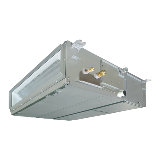
- Page 1 AIR CONDITIONER (SPLIT TYPE) Installation Manual Indoor Unit For commercial use Model name: Concealed Duct Type RAV-HM561BTP-E RAV-HM801BTP-E RAV-HM901BTP-E RAV-HM1101BTP-E RAV-HM1401BTP-E RAV-HM1601BTP-E English...
-
Page 2: Table Of Contents
• The qualified installer is a person who installs, maintains, relocates and removes the air conditioners made by Toshiba Carrier Corporation. He or she has been trained to install, maintain, relocate and remove the air Contents conditioners made by Toshiba Carrier Corporation or, alternatively, he or she has been instructed in such operations by an individual or individuals who have been trained and is thus thoroughly acquainted with the knowledge related to these operations. - Page 3 Warning indications on the air conditioner unit Definition of Protective Gear When the air conditioner is to be transported, installed, maintained, repaired or removed, wear protective gloves and “safety” work clothing. Warning indication Description In addition to such normal protective gear, wear the protective gear described below when undertaking the special work detailed in the following table.
-
Page 4: Precautions For Safety
– 3 – • Wear protective gloves and safety work clothing during Precautions for safety installation, servicing and removal. The manufacturer shall not assume any liability for the damage • Do not touch the aluminum fi n of the outdoor unit. You may caused by not observing the description of this manual. - Page 5 Selection of installation location • If refrigerant gas has leaked during the installation work, ventilate the room immediately. If the leaked refrigerant gas • When the air conditioner is installed in a small room, provide comes in contact with fire, noxious gas may generate. appropriate measures to ensure that the concentration of •...
- Page 6 – 5 – Electrical wiring Test run • Only a qualified installer(*1) or qualified service person(*1) is • Before operating the air conditioner after having completed the allowed to carry out the electrical work of the air conditioner. work, check that the electrical control box cover of the indoor Under no circumstances must this work be done by an unit and service panel of the outdoor unit are closed, and set unqualified individual since failure to carry out the work properly...
- Page 7 Relocation CAUTION • Only a qualifi ed installer(*1) or qualifi ed service person(*1) is This Air Conditioner has adopted a refrigerant HFC (R32) allowed to relocate the air conditioner. It is dangerous for the air which does not destroy the ozone layer. conditioner to be relocated by an unqualifi...
-
Page 8: Accessory Parts
– 7 – Accessory parts Selection of installation place ■ Accessory parts Avoid installing in the following places Select a location for the indoor unit where the cool or warm air will circulate evenly. Avoid installation in the following kinds of locations. Saline area (coastal area) Part name Q’ty... - Page 9 ■ ■ Installation under high-humidity atmosphere Installation space (Unit: mm) In some cases including the rainy season, especially inside of the ceiling may become high-humidity atmosphere Reserve sufficient space required for installation or service work. (dew-point temperature: 23°C or higher). 1.
-
Page 10: Installation
– 9 – ■ ■ Installation of hanging bolt Installation of indoor unit Installation Consider the piping / wiring after the unit is hung to Treatment of ceiling determine the location of the indoor unit installation CAUTION The ceiling differs according to structure of building. and orientation. -
Page 11: Drain Piping
■ Mounting filter rails and filters Drain piping Mount the fi lter rail so that the hooks fi t into the corresponding holes. CAUTION (Note that the upper and lower fi lter rails are not identical.) Following the Installation Manual, perform the drain piping work so that water is properly drained. Apply a heat insulation so as not to cause a dew condensation. - Page 12 – 11 – ■ ■ Gravitational drainage Check the draining In the test run, check that water drain is properly performed and water does not leak from the connecting part of Reattach the drain cap. the pipes. When doing this, also check that no abnormal sounds are heard from the drain pump motor. * For gravitational drainage, remove the white connector Check draining also when installed in heating period.
- Page 13 ■ ■ Heat insulating process Fan characteristics HM56 HM80 As shown in the figure, cover the flexible hose and hose band with the attached heat insulator up to the bottom of the indoor unit tightly. Standard air volume: 800 m Standard air volume: 1200 m Cover the drain pipe tightly with a heat insulator procured locally so that it overlaps with the attached heat insulator of the drain connecting section.
-
Page 14: Duct Design
– 13 – Duct design ■ Arrangement (Unit: mm) Referring to the following dimensions, manufacture duct at the local site. HM56 HM80 HM90, HM110, HM140, HM160 <Under air intake> <Under air intake> <Under air intake> 959.4 1359.4 659.4 37.5 37.5 37.5 37.5 37.5... -
Page 15: Refrigerant Piping
■ Evacuation CAUTION Refrigerant piping Perform vacuuming from the charge port of valve of Do not scratch the inner surface of the flared part the outdoor unit by using a vacuum pump. ■ when removing burrs. Connecting refrigerant piping CAUTION For details, follow to the Installation Manual attached Flare processing under the condition of scratches to the outdoor unit. -
Page 16: Electrical Connection
– 15 – Heat insulation process Electrical connection Apply heat insulation for the pipes separately at liquid side and gas side. For the heat insulation to the pipes at gas side, be sure to use the material with heat-resisting temperature 120°C or higher. - Page 17 ■ ■ Communication type Wiring between indoor unit and outdoor unit TU2C-Link can be used with these models. 1. Figure below shows the wiring connections between the indoor and outdoor units and between the indoor units If the indoor unit and the connected remote controller / remote sensor are all TU2C-Link models, TU2C-Link and remote controller.
-
Page 18: Applicable Controls
– 17 – ■ Wire connection Applicable controls REQUIREMENT ■ Applicable controls setup • For using the wired remote controller RBC-AMS55E*, Connect the wires matching the terminal numbers. Incorrect connection causes a trouble. refer to the Owner’s Manual attached to the wired (settings at the site) Pass the wires through the bushing of wire connection holes of the indoor unit. - Page 19 ■ ■ ■ Filter sign setting External static pressure External static pressure Each time [ ] [ ] setting button is pushed, settings indoor unit numbers in the group control When using the wireless remote controller According to the installation condition, the filter sign change cyclically.
- Page 20 – 19 – ■ ■ ■ Group control Remote controller sensor 8°C operation The temperature sensor of the indoor unit senses Pre-heating operation can be set for cold regions Simultaneous twin system room temperature usually. Set the remote controller where room temperature drops to below zero. A combination with an outdoor unit allows simultaneous ON/OFF operation of the indoor units.
- Page 21 ■ Group control for system of multiple units Manual address setting One group can control up to 16 (TU2C-Link) or 8 (TCC-Link) indoor units with one remote controller. (Refer to the Wiring specifications) Push and hold menu button and [ ] setting button simultaneously for 10 seconds or more. Push OFF timer button to confirm the selected indoor unit.
-
Page 22: Test Run
– 21 – Wired remote controller Test run Cooling test run Heating test run When TEMPORARY button is pushed for 10 ■ Before test run Set the temperature Set the temperature seconds or more, “Pi!” sound is heard and the Push and hold OFF timer button and [ ] to 17°C with the temp. -
Page 23: Maintenance
■ Monitoring function Indoor unit data Maintenance Code No. Data name This function can be used to call the service monitor Room temperature (remote controller) mode from the remote controller during a test run to <Daily maintenance> obtain the temperature of the sensors of the remote Indoor unit intake air temperature (TA) 4 Cleaning of the air filter controller, indoor unit, and outdoor unit. -
Page 24: Troubleshooting
– 23 – Periodic Maintenance Troubleshooting For environmental conservation, it is strongly recommended that the indoor and outdoor units of the air conditioner in use be cleaned and maintained regularly to ensure efficient operation of the air conditioner. When the air conditioner is operated for a long time, periodic maintenance (once a year) is recommended. ■... - Page 25 ■ Error codes and parts to be checked Wired Wireless remote remote controller Sensor block controller display of receiving unit Judging Wired display Main problem parts Parts to be checked / error description conditioner Wireless remote device remote status controller Sensor block Operation Timer controller display of receiving unit...
-
Page 26: Specifications
Flashing Model Weight (kg) GR GR OR Cooling Heating Abnormal temperature was detected by the temp, RAV-HM561BTP-E Heat sink overheat Outdoor Entire stop sensor of the IGBT heat sink. RAV-HM801BTP-E Drain pipe, clogging of drainage, float switch Indoor unit water Indoor circuit, indoor P.C. - Page 27 Declaration of Conformity Declaration of Conformity Manufacturer: Toshiba Carrier (Thailand) Co., Ltd. Manufacturer: Toshiba Carrier (Thailand) Co., Ltd. 144/9 Moo 5, Bangkadi Industrial Park, Tivanon road, Tambol Bangkadi, 144/9 Moo 5, Bangkadi Industrial Park, Tivanon road, Tambol Bangkadi, Amphur Muang, Pathumthani 12000, Thailand...
-
Page 28: Appendix
– 27 – Appendix Existing pipes: Cannot be used. Are there scratches or dents on the existing pipes? Use new pipes. Work instructions 5. When a commercially available dryer is attached to the existing pipes. Is it possible to operate the existing air conditioner? The existing R22 and R410A piping can be reused for There is the possibility that copper green rust has inverter R32 product installations. - Page 29 144 / 9 Moo 5, Bangkadi Industrial Park, Tivanon Road, Tambol Bangkadi, Amphur Muang, Pathumthani 12000, Thailand 1128950185...