Table of Contents
Advertisement
Quick Links
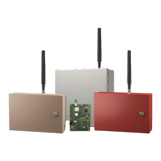
Honeywell Connected Life Safety
Services HW-TG7FS-V and HW-TG7FS-A
CLSS-Enabled 5G/LTE-M Commercial Fire Alarm Communicators
Installation and Operating Guide
These products are manufactured by Telguard® and are equivalent to model TG-7FS. These
part numbers are designated for Honeywell customers to indicate compatibility with
Honeywell Connected Life Safety Services ("CLSS").
HW-TG7FS-A is equivalent to Telguard part number TG7FS-A, for use with AT&T
cellular service in the United States of America and Canada.
HW-TG7FS-V is equivalent to Telguard part number TG7FS-V for use with Verizon
Wireless cellular service in the United States of America.
Advertisement
Table of Contents
Troubleshooting

Related Manuals for Honeywell HW-TG7FS-V


Summary of Contents for Honeywell HW-TG7FS-V
- Page 1 HW-TG7FS-A is equivalent to Telguard part number TG7FS-A, for use with AT&T cellular service in the United States of America and Canada. HW-TG7FS-V is equivalent to Telguard part number TG7FS-V for use with Verizon Wireless cellular service in the United States of America.
- Page 2 ONNECTED AFETY ERVICES This guide with help you with the steps that you need to follow to configure the HW-TG7 Series devices with Honeywell Connected Life Safety Services (CLSS). Honeywell CLSS is a cloud platform that enables systems integrators and facilities managers to deliver an enhanced fire safety service, while maximizing the performance efficiencies offered by Honeywell's trusted detection and alarm systems.
- Page 3 Telguard TG-7 Series Installation and Operating Guide for models TG-7, TG-7A, TG-7FS, TG-Kit, and TG-7UBL COMPANY CONFIDENTIAL ® For use by TELGUARD customers only. Distribution to other parties strictly prohibited. February 7, 2020...
- Page 4 Important Note The registration form must be completed before leaving for the job site to install the Telguard product. Use our dealer site at www.telguard.com to register the unit in real time. Foreword Dealers purchase Telguard cellular communicators for the quality, features and total value they represent. ®...
- Page 5 Repair and Warranty If trouble is experienced with the Telguard Cellular Alarm Communicator please contact Telguard Technical Support for trouble shooting, repair and (or) warranty information. The dealer or end user should not attempt any repair to the Telguard Cellular Alarm Communicator.
- Page 6 INDEMNIFICATION OF TELGUARD YOU SHALL INDEMNIFY, DEFEND AND HOLD HARMLESS TELGUARD FOR ANY OF THE COST, INCLUDING REASONABLE ATTORNEYS’ FEES, AND FROM CLAIMS ARISING OUT OF YOUR, YOUR CLIENTS’ OR OTHER THIRD PARTIES’ USE OR OPERATION OF THE PRODUCT: (i) FOR MISUSE OR IN A MANNER NOT CONTEMPLATED BY YOU AND TELGUARD OR INCONSISTENT WITH THE PROVISIONS OF THIS MANUAL;...
-
Page 7: Table Of Contents
Table of Contents Important Note Foreword Table of Contents General Description and Operation Features Operating Mode Multiple Alarm Format Support Complete Supervision of Communication Path Link Supervision and Standard Line Security Complete Power Supervision Telguard Automatic Self-test Report Telguard Remote Query Capability Programmable Supervisory Trip Output (STC) Relays Post-Installation Remote Programming (Commercial Fire Applications and All Applications in Canada) Diagnostic and Status LEDs... - Page 8 Step 8: Connect Tamper Switch (mandatory for Commercial Burglary Installations in Canada) Appendix 1 – Connection Guide Wiring Diagrams Tamper Switch Installation for UL/ULC Commercial Burglary Applications Jack Assignments Main Terminal Strip Pin Assignments DC Terminal Strip Pin Assignments A/C Terminal Strip Pin Assignments Compatible Alarm Panels Appendix 2 –...
-
Page 9: General Description And Operation
General Description and Operation The Telguard TG-7 series is a line of digital cellular radio alarm transmission devices used to provide the following three methods of communications for alarm panels via a cellular network: • Sole path (Cellular Transmission Only) •... - Page 10 MODEL APPLICATION UL/ULC STANDARDS TG-7 (standard unit. Part Commercial, Industrial, Retail UL 365, UL 985, UL 1023, UL 1610, ULC # TG7LA002– AT&T & Financial Markets for use in S545, ULC C1023, and ULC S304 Service) United States and Canada TG-7 (standard unit.
-
Page 11: Features
Features This section summarizes the key features of the Telguard TG-7 series. Operating Mode The Telguard is a digital cellular Data/SMS transmission device that is installed at the protected premises to provide alarm transmission for security systems. The Telguard TG-7 series transmits alarm signals over the nationwide digital cellular network if the telephone line or data network has been disrupted, compromised or when there is no wire line service available. -
Page 12: Link Supervision And Standard Line Security
Note: When the Telguard unit is configured as the Sole communications path, the Line Fault Condition (LFC) is disabled. No Service Condition (NSC) A no service condition (NSC) occurs when the Telguard device is unable to register with the cellular network. NSC can be configured to trip the supervisory relay output (STC relay) after a programmable period of time. -
Page 13: Complete Power Supervision
the initial account activation is done, the installer must verify the Link Supervision by turning off the device and making sure an alarm with the specific code is delivered. WARNING: Standard Line Security has only been evaluated between the TG-7 and the TCC. It is the responsibility of the installer to verify Standard Line Security from the Listed alarm panel to the Listed receiver through the TG-7 models as marked on the alarm panel and as indicated in the manufacturer's installation instructions... -
Page 14: Telguard Remote Query Capability
during registration and can accommodate any code the Central Station expects. The TCC captures all current and historical data pertaining to the operation of the Telguard device when it processes the automatic self-test signal. This data contains current operational status (C.O.S.) of the Telguard unit such as "All OK", "AC fail condition", "low/missing battery condition", or any combination of these as well as the current signal strength. -
Page 15: Post-Installation Remote Programming (Commercial Fire Applications And All Applications In Canada)
Post-Installation Remote Programming (Commercial Fire Applications and All Applications in Canada) Once a unit is installed in a Commercial Fire application or a location in Canada, it cannot be remotely reprogrammed without manual on-site intervention. To change the Telguard settings in such an installation, follow these steps: •... -
Page 16: Ul And Ulc Compliance
UL and ULC Compliance The TG-7 series includes models that are certified as complying with UL and ULC Standards for all Household Burglary, Household Fire, Commercial Burglary, and Commercial Fire installations. The chart on Page 2 shows the various models and the associated UL and ULC Standards. Certificates of Compliance are available at www.telguard.com. -
Page 17: Getting Ready
Getting Ready The Telguard device can only be activated when all necessary accounting information has been added to the customer database located at the TCC (i.e., the unit has been registered). The database includes information about the customer account, unit location, and system test plan information. Dealer Account Establishment A Dealer Account must be established prior to registration of any Telguard unit. -
Page 18: Installation
Installation Summary The following are steps necessary to install the Telguard device properly. NOTE: IF YOU DO NOT PROCEED IN THE ORDER AND MANNER PRESCRIBED, YOU MAY NOT COMPLETE THE INSTALLATION IN THE TIME DESIRED. These steps are summarized below and explained in detail in the remainder of this manual. Register for Telguard service Physically install the TG-7 Series device •... -
Page 19: Step 2: Physically Install The Tg-7 Series Device In Desired Location
installation requirements. The programming options for these supervisory trip outputs can be any combination of the following: • Always Off: Disables all relay supervisory functions. • ACFC: Trips 2 hours (programmable for up to 24 hours) after loss of AC power. Restores 60 seconds after AC power is restored. - Page 20 • Remember, the antenna should be as inconspicuous as possible for greatest visual security. • Try to keep the antenna away from sources of RF interference, including pumps, compressors, ovens, etc., or where metal objects can shield it or otherwise block the cellular radio RF signal. Place the antenna perpendicular to the ground, pointing either straight up or down.
-
Page 21: Step 3: Determine Antenna Placement For Best Performance
Step 3: Determine Antenna Placement for Best Performance Connect Antenna The Telguard unit is supplied with an antenna. In most cases the antenna can be mounted directly to the unit. If necessary, the antenna may be moved to a better signal location using an extension cable and bracket accessories (included with some models). -
Page 22: Step 6: Connect Supervisory Trip Outputs
The initial alarm is to confirm registration and activate the Telguard device. This alarm will NOT be transmitted to the central station. Special LED Indications during Activation If the Telguard unit fails the activation process, it will be displayed on the LEDs. •... -
Page 23: Step 7: Connect And Test The Trip Input (Optional)
Other failure conditions shall be triggered through STC2 and shall be treated as general trouble condition. • For Commercial Burglary installations which use the optional TG-PEM, consult the TG-PEM Manual for the configuration of STC1. Reprogram Alarm Panel to Send Proper Code If necessary, reprogram the alarm panel to send proper alarm code when tripped by the Telguard device’s supervisory output. - Page 24 TG-7 burglary models sold in Canada. The tamper switch needs to be connected to a zone on the panel and shall designate the zone as Tamper Protection. All Canadian Installations shall also meet the installation requirements of CAN/ULC-S302 standard for Installation and Classification of Burglar Alarm Systems for Financial and Commercial Premises, Safes and Vaults.
-
Page 25: Appendix 1 - Connection Guide
Appendix 1 – Connection Guide Wiring Diagrams The following wiring diagrams are for the Telguard TG-7 series used for: • Back-up path (Telco Primary & Cellular Back-up) • Primary path (Cellular Primary & Telco Back-up) • Sole path (Cellular Transmission Only) Scenario 1: Telco Connection through the Alarm Panel (Backup or Primary Mode) ULC Compliance Note:... - Page 26 Note 2: When using this scenario, LFC and CFC do not apply. LS10265-000HW-E:D 06/03/2021 56052901 – Rev B...
- Page 27 Scenario 2: Telco Connection through the Telguard (Backup or Primary Mode) Used when the TG-7 unit is working in a system that involves a Telco connection. In this case, the Telco is connected through the Telguard unit, and it is the TG-7 that monitors the Telco and cellular connection. It is the TG-7 that makes the decision of which communication path to use for signal delivery.
- Page 28 Scenario 3: No Telco connection (Cellular Only Mode) Used when the TG-7 unit is working in a system that does not involve a Telco connection. In this case, the Alarm Panel is connected directly to the TG-7, and there is no other connection for communication. REMOTE ANTENNA BATTERY...
- Page 29 Installation Using Conduit COVER 8 IN. 8 IN. 6 IN. FRONT VIEW SIDE VIEW LISTED PULL BOX WITH LISTED OUTLET BOX AND RECEPTACLE LISTED PULL BOX WALL LISTED TRANSFORMER LISTED OUTLET BOX AND RECEPTACLE ULTPDE.VSD LS10265-000HW-E:D 06/03/2021 56052901 – Rev B...
-
Page 30: Tamper Switch Installation For Ul/Ulc Commercial Burglary Applications
Tamper Switch Installation for UL/ULC Commercial Burglary Applications For all ULC Commercial Burglary Installations, a Tamper switch must be installed on TG-7 enclosure. The wiring from Tamper Switch to the panel shall be in a rigid or flexible metal conduit along with other wiring from TG-7 to the Panel. -
Page 31: Jack Assignments
Jack Assignments Connects Status LED Jack Pin Assignment Function Reference 1 = Brown R1 2 = Blue Incoming STC LED 2 will flash Gray 4 = Green R (Ring) Connects Telco line to Telco RJ-45 3 times when Telco (J14) 5 = Red T (Tip) TG-7 series. -
Page 32: Compatible Alarm Panels
Provides primary Provided AC operational power to AC Power LED ON when AC is normal. 1 AC AC power transformer the Telguard and AC power LED OFF and STC LED 2 2 AC input. output battery charging Flashes 1 time when AC is low. (12VAC, 10VA). -
Page 33: Appendix 2 - Troubleshooting Guide
Appendix 2 – Troubleshooting Guide This section provides a summary of all LED indications and their meanings, as well as the expected behavior of the Telguard under various exception conditions. LED Indicator Guide – Normal Operating Mode LED Symbol Color Showing Indication Solid On... -
Page 34: Led Indicator Guide - Rssi Mode
LED Indicator Guide – RSSI Mode RSSI Value LED’s Lighted RF dBm NO SVC LED 5 = slow flash, LEDs 4-2 = off LED 5 = on, LEDs 4-2 = off ≤ -111 1½ LED 5 = on, LED 4 = slow flash ... -
Page 35: Troubleshooting Quick Reference Table
Troubleshooting Quick Reference Table Relay Radio Telguard Event LED Indication Internal Action Output Message ACFC PWR LED off. STC LED 2 flashes Optional Optional Switch to standby continuously 1 time. battery if present, monitor battery, monitor AC for restoral. No action on Panel Power. -
Page 36: Appendix 3 - Commercial Fire Sole Path Communicator Installation
Appendix 3 – Commercial Fire Sole Path Communicator Installation Starting with the 2010 edition of NFPA 72, the TG-7FS can be utilized as the sole path for fire communications. By following Telguard's installation guidelines, the installer can provide the best conditions for a stable, sole path connection. -
Page 37: Appendix 4 - Commercial Fire 6-Hour Supervision
Appendix 4 – Commercial Fire 6-hour Supervision The NFPA 72 2013 Edition updated the requirement to supervise the transmission path at least once every 6 hours, from an earlier version of 24 hours. This requirement is upheld in 2016 edition as well. Telguard commercial and fire products support this feature, and it must be enabled for each subscriber by selecting 6-hour supervision during registration. - Page 38 ULC Installation Requirements Summary Household Burglary Household Fire Household Commercial Burg Commercial Fire Burg/Fire Combination TG-7 TG-7 TG-7 TG-7 TG-7FS Telguard Model UL/ULC/cUL Listed Bell and Bell Housing AC transformer lines in conduit.** AC transformer plugged into un- switched outlet. AC transformer plugged into dedicated branch...
-
Page 39: Appendix 6 - Detailed Specifications
Appendix 6 – Detailed Specifications Dialer to Interface Electronics The patented integrated interface by Telguard, allows digital dialers to dial into the cellular radio network. • Line voltage: -30 Vdc into standard telephone device when on-hook. • Dial tone: Precision 350 + 440Hz +/- 1%. 10 digits dial out capability. •... -
Page 40: Appendix 7 - Accessories
Appendix 7 – Accessories ACD-12 12 feet of antenna cable and mounting bracket ACD-35 35 feet of low loss high performance antenna cable and mounting bracket ACD-50 50 feet of low loss high performance antenna cable and mounting bracket ACD-100 100 feet of low loss high performance antenna cable and mounting bracket HGDL-0 High Gain Directional Antenna...