Table of Contents
Advertisement
Quick Links
READ AND SAVE THESE INSTRUCTIONS
Address: 46101 Fremont Boulevard, Fremont, CA 94538
US Toll Free Number:
1-888-979-9889 - Technical Support
1-877-685-4384 - Customer Sales Support
www.deltabreez.com
VENTILATION FAN
TABLE OF CONTENTS
VFB160D6A3-DGL
2
3
4
5
6
8
12
12
13
14
15
15
16
Advertisement
Table of Contents

Related Manuals for Delta breez VFB160D6A3-DGL


Summary of Contents for Delta breez VFB160D6A3-DGL
-
Page 1: Table Of Contents
VENTILATION FAN VFB160D6A3-DGL TABLE OF CONTENTS Package Contents General Safety Information Preparation Wiring Diagrams Assembly Instructions - New Construction Assembly Instructions - Existing Construction Grille Installation Operation Care and Maintenance Troubleshooting Dimensions Product Specifications Warranty READ AND SAVE THESE INSTRUCTIONS Address: 46101 Fremont Boulevard, Fremont, CA 94538 US Toll Free Number: 1-888-979-9889 –... -
Page 2: Package Contents
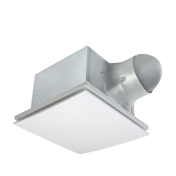
PACKAGE CONTENTS PART DESCRIPTION Fan Body Suspension bracket 6" to 4" adapter Grille HARDWARE CONTENTS (Images are to scale) × 8 Long Wood Screw ( Ø 4 x 25mm) × 4 Short Screw (#8-32x1/4”) -
Page 3: General Safety Information
GENERAL SAFETY INFORMATION READ AND SAVE THESE INSTRUCTIONS 7. If this unit is to be installed over a tub or shower, it must be marked as appropriate for the application and be GENERAL SAFETY INFORMATION connected to a GFCI (Ground Fault Circuit lnterrupter) – protected branch circuit. -
Page 4: Preparation
PREPARATION Tools Required for Assembly (not included): Hammer, Proper insulation around the fan to minimize building Flathead Screwdriver, Wire Nuts, Nails, Duct Tape, heat loss and gain. 6” circular duct is recommended for Phillips Head Screwdriver, Utility Knife installation. The ducting from this fan to the outside of Helpful Tools (not included): Electric Drill, Drill Bits building has a strong effect on the air flow, noise and energy use of the fan. -
Page 5: Wiring Diagrams
WIRING DIAGRAM QUICK CONNECTOR INSTRUCTIONS To be sold only with installation instructions. Quick connector WARNING: Wiring must comply with all appliable electrical codes. Turn OFF power before removing or installing House Product connectors. wires wires WARNING: COPPER TO COPPER ONLY. Do not use aluminum wire. -
Page 6: Assembly Instructions - New Construction
ASSEMBLY INSTRUCTIONS NEW CONSTRUCTION – ATTACHING TO THE JOIST Joist BEFORE INSTALLATION Turn off power source. Review all safety precautions. 1. If spacing between joists is 12 in. apart, use four long wood screws (provided) to attach the fan body to ceiling joists, NO NEED FOR SUSPENSION BRACKETS. - Page 7 ASSEMBLY INSTRUCTIONS 3. Remove the fan junction box cover . Using wire nuts (not supplied), connect house wires to fan wires as shown in the wiring diagram on page 5. 14AWG is the smallest conductor that shall be used for branch-circuit wiring. Reattach fan junction box cover 4.
-
Page 8: Assembly Instructions - Existing Construction
ASSEMBLY INSTRUCTIONS EXISTING CONSTRUCTION BEFORE INSTALLATION Turn off power source. Review all safety precautions. 1. Remove existing fan. 2. Measure the opening to ensure it is large enough to accommodate the new fan body (10 1/4 in. x 10 1/4 in.). 3. - Page 9 ASSEMBLY INSTRUCTIONS Install from below, no need for suspension brackets (no attic access) 4. Remove fan unit by removing 3 screws. 5. Remove duct connector by removing duct screw. Duct screw 6. A piece of wood (not supplied) is screwed in from Wood support screwed in from below through the ceiling board.
- Page 10 ASSEMBLY INSTRUCTIONS 7. Remove the fan junction box cover . Using 2 wire nuts (not supplied), connect house wires to fan wires a s shown in the wiring diagram on page 5. 14AWG is the smallest conductor that shall be used for branch-circuit wiring.
- Page 11 ASSEMBLY INSTRUCTIONS Install from above with suspension brackets (attic accessible) Fan Body *ONLY IF UNABLE TO ATTACH DIRECTLY TO JOIST(S) 1. For joist spacing 16 in.- 24 in., insert suspension bracket into the bracket cover on the duct connector side and the back of the fan body Suspension Bracket Install the suspension brackets to the joists with long wood screw, and secure the suspension brackets to...
-
Page 12: Grille Installation
GRILLE INSTALLATION Attach grille by pinching mounting springs insert into the narrow rectangular slots in fan body. OPERATION Turn the POWER switch on to operate at full speed airflow. -
Page 13: Care And Maintenance
CARE AND MAINTENANCE See safety information before proceeding. Routine maintenance should be done at least once a year. • Never use solvents, thinner or harsh chemicals when cleaning the fan. • Do not allow water to enter the motor. • Do not immerse metal parts in water. -
Page 14: Troubleshooting
TROUBLESHOOTING PROBLEM POSSIBLE CAUSE CORRECTIVE ACTION The fan is not turning on 1. Power off 1. Make sure power supply is on. 2. Faulty switch 2. Test or replace switch. 3. Faulty wire connection 3. Check wire in switch box. The fan seems louder 1. -
Page 15: Dimensions
DIMENSIONS 1 9/16 7 7/8 (40.0) (200) 12 3/8 (314.0) Unit: Inches(mm) 9 21/32 3 3/4 (245.4) (94.4) PRODUCT SPECIFICATIONS Air Flow @ Power @ Voltage Frequency Max Current Weight Model No. 0.1"SP 0.1"SP Note (Hz) (Amps) (lb.) (CFM) Single VFB160D6A3-DGL 16.4 0.38... -
Page 16: Warranty
6. To qualify for warranty service, you must notify Delta Electronics at the address or telephone number below. 7. Delta Electronics shall have no liability to the original owner-user with respect to any defect caused by abuse, misuse, neglect, improper transportation or storage, improper testing, improper installation, improper operation,...