Delta Breez VFB25ACH Manual
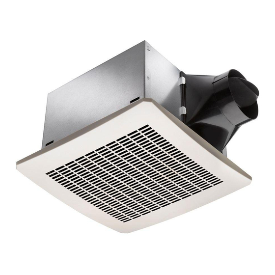
Ventilation fan
Hide thumbs
Also See for Breez VFB25ACH:
- Installation and operating instructions manual (7 pages) ,
- Instructions manual (12 pages)
Table of Contents
Advertisement
READ AND SAVE THESE INSTRUCTIONS
Address: 46101 Fremont Boulevard, Fremont, CA 94538
US Toll Free Number:
1-888-979-9889 - Technical Support
1-877-685-4384 - Customer Sales Support
www.deltabreez.com
VENTILATION FAN
MODELS VFB25ACH / VFB25ADH / VFB25AEH
TABLE OF CONTENTS
80HS / 80-110DS / 110F / 130HS
MFG Model
VFB080D4H1 / VFB110D4X1
VFB110D4A1 / VFB130D4H1
2
3
4
5
7
10
10
12
13
13
14
14
Advertisement
Table of Contents

Related Manuals for Delta Breez VFB25ACH


Summary of Contents for Delta Breez VFB25ACH
-
Page 1: Table Of Contents
VENTILATION FAN MODELS VFB25ACH / VFB25ADH / VFB25AEH 80HS / 80-110DS / 110F / 130HS TABLE OF CONTENTS Package Contents General Safety Information Preparation and Wiring Diagrams Assembly Instructions - New Construction Assembly Instructions - Existing Construction Grille Installation Operation Care and Maintenance Troubleshooting Dimensions... -
Page 2: Package Contents
PACKAGE CONTENTS PART DESCRIPTION Fan Body Grille Suspension Bracket I Suspension Bracket II Suspension Bracket III Duct Connector HARDWARE CONTENTS (Images are to scale) × 8 Long Wood Screw ( ø 4 x 25mm) × 3 Short Machine Screw (M4 x 12mm) -
Page 3: General Safety Information
GENERAL SAFETY INFORMATION READ AND SAVE THESE INSTRUCTIONS 6. Ducted ventilating fans must always be vented to the outdoors. GENERAL SAFETY INFORMATION 7. If this unit is to be installed over a tub or shower, it 1. Make sure that the electric service supply voltage is AC must be marked as appropriate for the application 120V, 60Hz. -
Page 4: Preparation And Wiring Diagrams
However, most are available at your local home improvement Use a roof cap or wall cap that has a built-in damper to or hardware store. reduce backdrafts. External timer can be used. Please contact Delta Breez DIMENSION REQUIREMENTS customer service and consult with a licensed electrician for compatibility... -
Page 5: Assembly Instructions - New Construction
ASSEMBLY INSTRUCTIONS NEW CONSTRUCTION – ATTACHING TO THE JOIST BEFORE INSTALLATION Turn off power source. Review all safety precautions. 1. If spacing between joists is 12 in. apart, use four long wood screws (provided) to attach the fan body to ceiling joists. Hardware Long wood screw 2. - Page 6 ASSEMBLY INSTRUCTIONS 4. Secure the suspension brackets to the fan body using a short machine screw. Hardware Short machine screw Short machine screw 5. Remove the fan junction box cover . Using wire nuts (not supplied), connect house wires to fan wires as shown in the wiring diagram on page 4.
-
Page 7: Assembly Instructions - Existing Construction
ASSEMBLY INSTRUCTIONS EXISTING CONSTRUCTION NOTE: ATTACHING DIRECTLY TO THE JOIST(S) FROM BELOW WILL BE THE BEST INSTALLATION. BEFORE INSTALLATION Turn off power source. Review all safety precautions. 1. Remove existing fan. 2. Measure the opening to ensure it is large enough to accommodate the new fan body (10 1/4 in. -
Page 8: Duct Connector
ASSEMBLY INSTRUCTIONS 5. Place the duct connector through the ceiling cut out. Connect a 4 in. circular duct (not supplied) and vent to the outside. Secure it with duct tape (not supplied) or clamp (not supplied) to make connection secure and air tight. Attach the duct connector to the ceiling with one long wood screw. - Page 9 ASSEMBLY INSTRUCTIONS Install from above with suspension brackets (attic access) *ONLY IF UNABLE TO ATTACH DIRECTLY TO JOIST(S) 1. For joist spacing 16 in. - 24in., insert suspension bracket I into the bracket cover on the duct connector side. Then, attach suspension bracket II and bracket III to the back of the fan body 2.
-
Page 10: Grille Installation
GRILLE INSTALLATION Attach grille by pinching mounting springs insert into the narrow rectangular slots in fan body OPERATION Single Speed Model: 110F Turn the POWER switch ON to operate at single speed mode. Humidity Sensor Models: VFB25ACH, VFB25ADH, VFB25AEH, 80HS, 130HS 1. - Page 11 OPERATION Dual Speed Model: 80-110DS 1. Low Speed Mode: Flip wall switch to “ON” position. The LED indicator light in the fan will be GREEN. Green LED Light 2. Full Speed Mode: Cycle wall on/off switch. The LED indicator light in fan will be AMBER. Amber LED Light 3.
-
Page 12: Care And Maintenance
CARE AND MAINTENANCE See safety information before proceeding. Routine maintenance should be done at least once a year. • Never use solvents, thinner or harsh chemicals when cleaning the fan. • Do not allow water to enter the motor. • Do not immerse metal parts in water. •... -
Page 13: Troubleshooting
TROUBLESHOOTING PROBLEM POSSIBLE CAUSE CORRECTIVE ACTION The fan is not turning on 1. Power off 1. Make sure power supply is on. 2. Faulty switch 2. Test or replace switch. 3. Faulty wire connection 3. Check wire in switch box. The fan seems louder 1. -
Page 14: Product Specifications
4. This warranty does not extend to fluorescent lamp starters and tubes. 5. The warranty does not cover if user does not comply with manufacturer’s installation manual. 6. To qualify for warranty service, you must notify Delta Electronics at the address or telephone number below.