
Related Manuals for Axminster AP254PS13


Summary of Contents for Axminster AP254PS13
- Page 1 Code 107715 Original Instructions AT254PS13 Panel Saw AT: 13/01/2021 BOOK VERSION: 5...
- Page 2 36-37-38 Wiring Diagram Exploded Diagrams/Lists 39-40-41-42-43-44-45-46-47-48 Notes 49-50 Cert No: P250/230 EU Declaration of Conformity Axminster Tool Centre Ltd This machine complies with the following directives: Axminster Devon EX13 5PH UK axminstertools.com 2006/42/EC 06/42/EC - Annex I/05.2006 2006/95/EC EN IEC 61000-3-2:2019...
-
Page 3: What's Included
What’s Included Quantity Item Part Model Number AP254PS13 Main Saw Assembly (upper chassis Workpiece Support Shoe with motor, table, saw blade and Sliding Table Fence Assembly NVR switch fitted) Sliding Table Operating Handle Side Panels and Front and Back Panels... - Page 4 What’s Included...
- Page 5 What’s Included Eight small Phillips screws for mounting the capping plates above.
-
Page 6: General Instructions For 230V Machines
General Instructions for 230V Machines balanced, not reaching etc. If the work you are carrying Good Working Practices/ Safety out is liable to generate flying grit, dust or chips, wear the The following suggestions will enable you to observe appropriate safety clothing, goggles, gloves, masks etc. If good working practices, keep yourself and fellow the work operation appears to be excessively noisy, wear workers safe and maintain your tools and equipment... -
Page 7: Specification
If any tools have been used during setting up procedures, make sure they are removed from the machine and stowed safely away. Specification Code 107715 Model AP254PS13 Rating Professional Power 2.2kW 230V 1ph Blade Dia/Bore 254 x 30 mm... - Page 8 Assembly PLEASE NOTE: Some of this assembly PLEASE NOTE: The panel saw comes 80% assembled, in order to reduce the footprint of the machine for procedure is best accomplished by two packaging, several items are dismounted from the persons, some of the items are heavy and machine and need to be re-affixed.
- Page 9 Assembly 2. Introduce the front panel (2) between the two col- umns to the front of the saw body. Line up the holes and lightly secure with M8 bolts (A). Repeat the procedure for the back and one of the side panels, see fig 03-04-05. Fig 03-04-05 4.
- Page 10 Assembly Hex screw/washer 9. Insert one of the square keys into the machined slot on the drive shaft, see fig 16. Line up the machined key slot to the centre of the hand wheel (16) with the key and slide the wheel onto the drive shaft. Replace the Hex screw/washer you removed earlier and tighten securely, see fig 17-18.
- Page 11 Assembly Fig 22-23 10. With everything secure, with assistance tip the main saw over towards its blind face until it is resting on the pallet. With its legs on the floor lift the machine upright, see fig 19. Fig 19 Side Access Door Knob (If not already assembled) Straight edge 11.
- Page 12 Assembly 15. Loosen the two bolts holding the mounting plates. Lower the riving knife (12) down between the mounting plates, set the riving knife close to the blade and check the clearance between the blade. It should have a gap of (MIN 3mm - MAX 8mm), tighten the two bolts to secure the setting, see fig 29-30-31-32.
- Page 13 Assembly curved slot in the riving knife. Tighten the clamping 18. Place the remaining clip over the opposite end of the knob, see fig 33-34. hose. Insert the hose over the 50mm inlet on the 100mm extraction moulding (17) and tighten the clip, see fig 37. Fig 3-34 Fig 37 Curved slot...
- Page 14 Assembly opposite end of the main saw table (1), see fig 43-44. Sliding Table Position the sliding table (10) so its over hangs equally to both end of the main table (1). You will require the following: the sliding table extension Fig 43-44 support arm (27), sliding table assembly (10), sliding table fence (24), sliding table extension (11), mitre fence (14)
- Page 15 Assembly 25. Locate the sliding table extension (11), line up the 26. Locate the sliding table supporting leg (27), loosen two ‘T’ bolts on the extension table with the ‘T’ slots to the square bolt on top of the leg support. To the the side of the sliding table (10) and slide on the underside of the sliding table (10), Insert the square bolt extension table, see fig 47.
- Page 16 Assembly Fig 54-55-56-57-58 Blade 30. Locate the distance stop assembly (26). Loosen the butterfly clamping knob beneath the fence assembly (24) and pull out the telescopic fence section out. Loosen the clamping handle on the distance stop (26), insert the ‘T’ bolt into the ‘T’...
- Page 17 Assembly 32. Loosen the ‘T’ bolt in the sliding table’s operating Rip Fence handle (25). Insert the ‘T’ bolt into the ‘T’ slot into the You will require the following: the rip fence (9), rip fence opposite end of the table and secure in place, see rail (7), micro adjuster (8), capping plates (D), small Phillips fig 64-65.
- Page 18 Assembly Fig 76-77-78 Rip fence scale out of alignment 36. Reach under the table’s edge and lightly tighten all the nuts. Re-attach the capping plate (D), see fig 73-74. 37. Locate the rip fence assembly (9) and lower the clamping assembly over the fence rail (7). Raise the clamping handle and slide the rip fence up against the blade, see fig 75.
- Page 19 Assembly Pinion Phillips screw Mitre Fence assembly for sliding Table Micro Adjuster 42. Locate the mitre fence housing (14), mitre fence extension (15), locking knob, clamping handle and 40. Locate the micro adjuster (8). Remove the rip fence workpiece clamp shaft. Replace the mounting bar (a) as assembly from the fence rail (7) and remove the capping shown in step 33.
- Page 20 Assembly 43. Locate the overhead clamp assembly (28), insert 45. Adjust the mitre fence assembly until it reads ‘zero’ either mounting hole down over the shaft and lock in on the sliding tables scale. place with the clamping knob, see fig 87. 46.
- Page 21 Machine Footprint 1 Metre extension 1,120mm...
-
Page 22: Machine Footprint
Machine Footprint... -
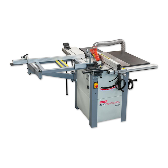
Page 23: Illustration And Parts Description
Illustration and Parts Description Riving knife Sliding table Workpiece Rip fence support shoe Sliding table fence Rip fence rail Sliding table extension Rip fence clamp Support arm Sliding table support leg Sliding table mitre fence Main saw assembly NVR switch/ Emergency stop Work clamp Crown guard Side access door... - Page 24 Illustration and Parts Description Rear extension table Flexible hose Hose support bracket Right hand table Sliding table extension Distance stop assembly Micro adjuster 45˚ operating handle Telescopic extension Rise & full operating handle Sliding table operating handle Mounting plate NVR Switch with Emergency stop shroud Distance stop assembly.
- Page 25 Illustration and Parts Description Rip fence scale magnifying glass 45˚ Scale and pointer Main saw table, height adjusting Over head clamp assembly 100 mm Dust extraction outlet bolts, one to each corner beneath the table Saw assembly: The Blade (A), Sliding locking pin assembly Crown Guard (B) and Riving Knife (C) Twist the knob to engage or disengage the locking pin...
- Page 26 Illustration and Parts Description Motor/tilt assembly side access door Telescopic fence extension Unlock the butterfly clamp beneath the fence to extend the fence by a metre Sliding table mitre fence with over head clamp (A), Rip Fence assembly Fence angle clamp (B), Over head clamp (C) Rip fence clamp (A), Micro adjuster (B), Magnifying glass (C) and Scale (D) Drive belt tensioning bolt...
- Page 27 Illustration and Parts Description 90˚ fence stop Sliding table extension scale Grub screws Rise and full control wheel (A), Control wheel locking lever (B), Sliding table extension angle Blade tilt locking knob (C) and 45˚Control wheel (D) adjusting grub screws...
-
Page 28: Positioning The Machine
Positioning the Machine Ascertain the orientation of the machine and move it wish to machine. The machine should be positioned on to its desired position in the workshop. Ensure that the a flat level surface. Manoeuvre the machine to the machine is positioned to allow sufficient clearance all chosen location, then carefully lower the machine down. - Page 29 Setting Up the Machine 4. Using a steel rule measure 30mm back from the saw tip, so the scale on the rule lines up with the 30mm on the fence scale (24), see fig 98. Secure the fence again as described in step 1.
- Page 30 Setting Up the Machine Fig 101 NOTE: Check that the sliding table is still level with the main table as it may have shifted when tightening up the bolts. Fig 104-105 Feeler gauge Clamping bolts 3. Place a rule across both tables and measure the distance between both ‘T’...
- Page 31 Setting Up the Machine Fig 107-108 Fig 110-111-112-113 Inner guard Rip fence scale out of alignment Mounting plate 4. Loosen the bolts holding the riving knife, see fig 108. Adjust the knife until the required clearance is correct and then retighten the bolts. Replace the inner guard and crown guard.
- Page 32 Operating Instructions Fig 116 CONNECT THE MACHINE TO THE MAINS! Connect the machine to the mains supply, give the machine a test run, by pressing the On/Off buttons, see fig 114. Check that everything sounds and feels OK. (No knocking, scraping, belt squeal, rubbing etc). Switch off the machine, wait until the saw comes to a complete stop RECONNECT THE MACHINE TO THE MAINS! and disconnect the machine from the mains supply.
- Page 33 Operating Instructions Fig 118 NOTE: DURING OPERATION IF YOU NOTICE A BUILD UP OF SAW DUST STOP THE MACHINE AND FOLLOW THE INSTRUCTIONS BELOW. 3. Wait until the saw has stopped and disconnect the machine from the mains supply. 4. Move the sliding table (10) to one side, using a vacuum cleaner clean out any build up of dust debris or resin then slide the table to the opposite side and repeat the procedure.
- Page 34 Operating Instructions 3. Start the saw, wait until it’s at full speed and carefully feed the workpiece through using a ‘push stick’ . Make RECONNECT THE MACHINE TO THE MAINS! sure the workpiece is clear of the blade then turn off the saw, wait until the saw comes to a complete stop before Start the saw by pressing the ‘ON’...
-
Page 35: Changing The Saw Blade
Changing the Saw Blade Changing the Blade WARNING!! DISCONNECT THE MACHINE Blade locking bar FROM THE MAINS BEFORE CONTINUING! Blade 1. Raise the saw blade to it’s highest point. Remove the saw blade crown guard and place to one side. Pull the sliding table locking knob down and slide the table to the side exposing the blade. -
Page 36: Routine Maintenance
“Specialist After Sales Main Saw Blade Team” by phone on 03332 406 406 or visit our website at axminster.co.uk. 1. Slide the table to one side and remove the crown guard and inner guard, place safely aside. - Page 37 Routine Maintenance 4. Open the side access door , see fig 130-131, this gives Fig 134-135 access to the motor saw assembly. Loosen the four bolts holding the motor housing, see fig 132 then loosen Pulley grooves the belt tension bolt (a), see fig 133. Pull the motor for- ward to slacken off the drive belt.
-
Page 38: Wiring Diagram
Routine Maintenance Fig 137 Lubrication After every three or four months we recommend you lubricate the blade and the tilt, rise and fall screw threads using ‘Ambersil Dry PTFE Film Antistick’ spray, see fig 136-137. Fig 136 Blade Rise & fall mechanism Tilt thread Ambersil Dry PTFE Film Antistick spray Wiring Diagram... - Page 39 Exploded Diagrams/Lists DIAGRAM A Continues over...
- Page 40 Exploded Diagrams/Lists Description A-22 Switch box A-23 Rear panel, machine housing Hex nut M4 A-24 Lest frame, machine housing Hex nut M5 A-25 Right panel, machine housing Wire clamp Front panel, machine housing A-26 External teeth lock washer 5mm Right frame, machine housing A-27 Spring washer 4mm Column A...
- Page 41 Exploded Diagrams/Lists DIAGRAM B Continues over...
- Page 42 Exploded Diagrams/Lists Description B-24 Handle, fine adjust B-25 Taping screw ST4.2x10 Spring,gear B-26 Cap , fence Eccentric,fine adjust B-27 Plate, fence Seat, fine adjust Sunk head screw M5x6 B-28 Rod,gear Fence B-29 Gear Cap,fence B-30 Washer 8mm Guide plate, screw B-31 PVC sticker Countersunk screw M5x8...
- Page 43 Exploded Diagrams/Lists DIAGRAM C Continues over...
- Page 44 Exploded Diagrams/Lists Description C-57 Thicken washer 8 Blade nut M16(left-hand( C-58 Motor Outer blade washer C-59 Hexagon head bolt M8X40 Blade C-60 Key 8X7X50 Driving belt C-61 Hexagon socket set screw with flat point M6X8 Pulley C-62 Hexagon socket set screw with flat point M6X6 Key(A-type(...
- Page 45 Exploded Diagrams/Lists DIAGRAM D Continues over... Continues over...
- Page 46 Exploded Diagrams/Lists Description D-43 Bush, cross cut table D-44 Sliding tale T type bolt, sliding table D-45 Cross cut table Ratchet lever D-46 Locating pin set Flat washer 10mm Swing arm A D-47 Scale A Shaft A, swing arm D-48 Scale B Swing arm B D-49...
- Page 47 Exploded Diagrams/Lists DIAGRAM E Continues over...
- Page 48 Exploded Diagrams/Lists DESCRIPTION E-13 Flip stop Guide rail E-14 Flip stop base T type bolt,cross cut fence E-15 Hex nut M8 E-16 Lock plate Wing nut M8 E-17 Knurled knob Carriage bolt M8x25 E-18 Locating plate shaft End cap B Extension fence E-19 Set screw M5x6...
- Page 49 Notes...
- Page 50 Notes...
- Page 51 Notes...
- Page 52 The packaging is suitable for recycling. Please dispose of it in a responsible manner. EU Countries Only Do not dispose of electric tools together with household waste material. By law they must be collected and recycled separately. Axminster Tools, Axminster Devon EX13 5PH axminstertools.com...