Table of Contents
Advertisement
Quick Links
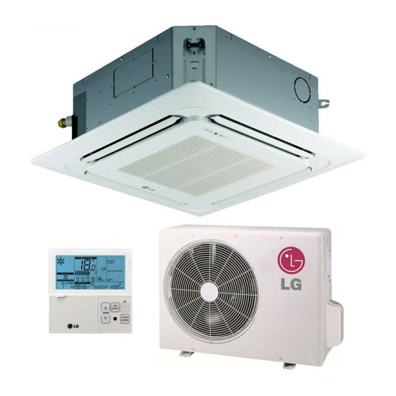
INSTALLATION MANUAL
AIR CONDITIONER
• Please read this installation manual completely before installing the product.
• Installation work must be performed in accordance with the national wiring
standards by authorized personnel only.
• Please retain this installation manual for future reference after reading it
thoroughly.
P/NO : MFL40910612
www.lg.com
Advertisement
Table of Contents

Related Manuals for LG UU12


Summary of Contents for LG UU12
- Page 1 • Please read this installation manual completely before installing the product. • Installation work must be performed in accordance with the national wiring standards by authorized personnel only. • Please retain this installation manual for future reference after reading it thoroughly. www.lg.com P/NO : MFL40910612...
-
Page 2: Table Of Contents
Air Conditioner Installation Manual TABLE OF CONTENTS Installation Required Parts Required Tools Requirements Safety Precautions ..3 Installation of Indoor, Outdoor unit ....6 • Connecting cable • Level • Four Type "A" Screw • Screw driver The indoor unit • Hanging Bolt •... -
Page 3: Safety Precautions
Safety Precautions Safety Precautions To prevent the injury of the user or other people and property damage, the following instructions must be followed. n Be sure to read before installing the air conditioner. n Be sure to observe the cautions specified here as they include important items related to safety. n Incorrect operation due to ignoring instruction will cause harm or damage. - Page 4 Safety Precautions Do not install the product at a place that there Use caution when unpacking and installing. is concern of falling down. • Otherwise, it may result in personal injury. • Sharp edges may cause injury. Use a vacuum pump or Inert (nitrogen) gas when doing leakage test or air purge. Do not compress air or Oxygen and Do not use Flammable gases.
- Page 5 Safety Precautions n Installation Install the drain hose to ensure that drain Install the product so that the noise or hot can be securely done. wind from the outdoor unit may not cause any damage to the neighbors. • Otherwise, it may cause water leakage. •...
-
Page 6: Installation Of Indoor, Outdoor Unit
Installation of Indoor, Outdoor Unit Installation of Indoor, Outdoor Unit Selection of the best location 1. Indoor unit Cassette type • There should not be any heat source or steam near the unit. Ceiling • There should not be any obstacles to prevent Ceiling Board Ceiling Board the air circulation. - Page 7 Installation of Indoor, Outdoor Unit Convertible type • Do not have any heat or steam near the unit. More than • Select a place where there are no obstacles in 70cm front of the unit. • Make sure that condensation drainage can be conveniently routed away.
- Page 8 Indoor unit Outdoor unit CAUTION: • Rated performance for refrigerant line length of:7.5m(UU12, UU18 : 5m) • Capacity is based on standard length and maximum allowance length is on the basis of reliability. • Improper refrigerant charge may result in abnormal cycle.
-
Page 9: The Indoor Unit Installation
The indoor unit installation The indoor unit installation 1. Cassette type Ceiling Ceiling board Level gauge TE Series TH/TD Series TM/TN/TP Series 600 (Ceiling opening) 875 (Ceiling opening) 875 (Ceiling opening) 39.5 521(Hanging bolt) 785(Hanging bolt) 39.5 787 (Hanging bolt) 570 Unit size 840 Unit size 840 Unit size... - Page 10 The Indoor Unit Installation Ceiling Keep the length of the bolt Hanging bolt from the bracket to 40mm (W3/8 or M10) Flat washer for M10 Air Conditioner body (W3/8 or M10) (accessory) Ceiling board Ceiling board Spring washer (M10) Flat washer for M10 (accessory) Set screw of Paper model...
- Page 11 The Indoor Unit Installation 2. Duct type CASE 1 POSITION OF SUSPENSION BOLT • Apply a joint-canvas between the unit and duct to absorb unnecessary vibration. • Apply a filter Accessory at air return hole. (Unit:mm) Dimension F (G) H Capacity UB30/UB36 1232 1182 355 45.5 450 87 830 186...
- Page 12 The Indoor Unit Installation • Select and mark the position for fixing bolts. • Drill the hole for set anchor on the face of ceiling. • Insert the set anchor and washer onto the suspension bolts for locking the Old building New building suspension bolts on the ceiling.
- Page 13 The Indoor Unit Installation CAUTION 1. Install declination of the indoor unit is very important for the drain of the duct type air conditioner. 2. Minimum thickness of the insulation for the connecting pipe shall be 5mm. Front of view •...
- Page 14 The Indoor Unit Installation 3. Convertible type Open side cover 1. Remove two screws from side-cover as shown in fig. 2. Unlock side-cover from side panel by slightly pulling the edge of side cover. Edge part 3. Tap the side-cover with your palm on the backside.(Inlet grill side.) 4.
- Page 15 The Indoor Unit Installation MOUNTING THE ANCHOR NUT AND BOLT DIM. • Prepare 4 suspension bolts. (Each bolts length MODEL should be same.) UV12 • Measure and mark the position for the UV18/24/30 1076/1236 Suspension bolts and the piping hole. UV36 1255 UV42/48/60...
- Page 16 The Indoor Unit Installation Indoor unit installation Hang the Indoor unit on suspension bolt as per following guidelines: 1. Lift the indoor unit to sufficient height. 2. Insert the suspended part of four suspension bolt in the four hangers provided on the side of main body one by one.
- Page 17 The Indoor Unit Installation 1) Indoor unit installation n Before Installing, prepare Installation Plates • 'Installation Plates' are attached at the bottom Side Plate of indoor unit. Detach them by removing each 3 screws at both sides. • Detach 'Side Plate (R,L)' by removing each 2 Install Plate screws on both sides.
- Page 18 The Indoor Unit Installation • Insert the nuts and washer onto the suspension bolts for locking the suspension Anchor nut bolts on the ceiling. Ceiling • Mount the suspension bolts to the anchor- nuts firmly. Washer Suspension • Secure the Installation plates onto the bolts Suspension bolts (adjust level roughly.) using nuts, washers and spring washers.
- Page 19 The Indoor Unit Installation CAUTION 1. Install declination of the indoor unit is very important for the drain of the convertible type air conditioner. 2. Minimum thickness of the insulation for the connecting pipe shall be 7mm. 3. If the Installation Plates are fixed to horizontal line, the indoor unit after installing will be declined to the bottomside.
- Page 20 The Indoor Unit Installation • Secure the unit to the Installation Plates with four M8 bolts and washers. • Before working, refer to "Connecting pipe to Indoor Unit" on page 16. • Hook up the Inlet Grille Hook to the cabinet. Inlet hanger •...
- Page 21 The Indoor Unit Installation 2) Installation on the Wall • Select and mark the position for fixing bolts and piping hole. Decide the position for fixing bolts slightly tilted to the drain direction after considering the direction of drain hose. •...
- Page 22 The Indoor Unit Installation Install the Indoor unit onto Installation Plate. • Insert 2 hooks on the both left and right side Inner slot of the unit to the inner slot (wall side) of the Installation Plate. • Secure the unit to the Installation Plate with four M8 bolts and washers.
- Page 23 The Indoor Unit Installation 3) Installation on the floor From the left wall Installation of Mount Bracket. more than 760mm • Select and mark the position for Mount Brackets and the piping hole. From the • Drill the hole for the anchor nut on the wall. right wall more than 840mm •...
-
Page 24: Remote Controller Installation
Remote Controller Installation Wired Remote Controller Installation 1. Please fix tightly using provided screw after placing remote controller setup board on the place where you like to setup. - Please set it up not to bend because poor setup could take place if setup board bends. Please set up remote controller board fit to the reclamation box if there is a reclamation box. - Page 25 Remote Controller Installation 3. Please fix remote controller upper part into <Connecting order> the setup board attached to the surface of the wall, as the picture below, and then, connect with setup board by pressing lower part. Wall Wall - Please connect not to make a gap at the remote controller Side Side and setup boardʼs upper and lower, right and left part.
- Page 26 Remote Controller Installation Wired remote controller installation • Since the room temperature sensor is in the remote controller, the remote controller box should be installed in a place away from direct sunlight, high humidity and direct supply of cold air to maintain proper space temperature.
-
Page 27: Wiring Connection
Wiring Connection Wiring Connection Connecting cables to the Indoor Unit • Remove the control box cover for electrical connection between the indoor and outdoor unit. (Remove screws ¿.) • Use the cord clamper to fix the cord. 1. Cassette type 2. - Page 28 (This equipment shall be provided with a cord set complying with the national regulation.). Capacity 1 Phase NORMAL UU12/18/24/30 2.5mm CROSS-SECTIONAL AREA 0.75mm (UU12/18/24/30/37) Capacity 3 Phase UU37 1.5mm...
- Page 29 • Connect the wires according to color codes by referring the wiring diagram. Capacity 1 Phase 3 Phase UU12 UU18/24 UU30 UU37 • The Power cord connected to the unit should be selected according to the following specifications. Connecting the cable to Outdoor Unit 1.
-
Page 30: Connecting Pipes To The Indoor Unit
Connecting Pipes to the Indoor Unit Connecting Pipes to the Indoor Unit Preparation of Piping Main cause of gas leakage is defect in flaring work. Carry out correct flaring work in the Copper Slanted Uneven Rough following procedure. tube 90° 1. - Page 31 Connecting Pipes to the Indoor Unit Piping Connection 1. Form the piping according to its routing. Avoid bending and bending back the same Liquid side piping point more than three times. (This will result in hardening the pipe.) Indoor 2. After deforming the piping, align centers of unit the union fitting of the indoor unit and the Outdoor...
-
Page 32: Installation To Decorative Panel
Installation to Decorative Panel Installation to Decorative Panel The decoration panel has its Before installing the decoration panel, installation direction. always remove the paper template. 1. Temporarily fix two decoration panel fixing screws (hexagon M5 screw) on the unit body. (Tighten by amount 10mm in length.) The fixing screws (hexagon M5 screw) are included the indoor unit box. -
Page 33: Indoor Unit Drain Piping
Indoor Unit Drain Piping CAUTION: Install certainly the decorative panel. Cool air leakage causes sweating. ⇨ Water drops fall. Good example Bad example Air conditioner unit Air conditioner Cool air leakage unit (no good) Ceiling Ceiling board board Decorative Decorative panel panel Fit the insulator (this part) and be careful for cool air leakage... - Page 34 Indoor Unit Drain Piping Drain test 1. Cassette type The air conditioner uses a drain pump to drain water. Use the following procedure to test the drain pump operation: • Connect the main drain pipe to the exterior and leave it provisionally until the test comes to an end.
- Page 35 Indoor Unit Drain Piping 3. Convertible type 1. Set the air direction louvers up-and-down to the position(horizontally) by hand. To check the drainage. 1. Pour a glass of water on the evaporator using a kettle. 2. Ensure the water flows through the drain hose of the indoor unit without any leakage and goes out the drain exit.
- Page 36 Indoor Unit Drain Piping Heat insulation 1. Use the heat insulation material for the refrigerant piping which has an excellent heat-resistance (over 120°C). 2. Precautions in high humidity Fastening band circumstance: (accessory) This air conditioner has been tested according to the "KS Standard Conditions with Mist"...
- Page 37 Indoor Unit Drain Piping In cases where the Outdoor unit is Seal a small opening installed above the Indoor unit around the pipings perform the following. with gum type sealer. 1. Tape the piping and connecting cable from down to up. 2.
-
Page 38: Test Running
Test running Test running 1. PRECAUTIONS IN TEST RUNNING • The initial power supply must provide at least 90% of the rated voltage. Otherwise, the air conditioner should not be operated. ① For test run, carry out the cooling operation firstly even during heating CAUTION season. - Page 39 Test running CAUTIO N: After the confirmation of the above conditions, prepare the wiring as follows: 1) Never fail to have an individual power specialized for the air conditioner. As for the method of wiring, be guided by the circuit diagram pasted on the inside of control box cover.
-
Page 40: Optional Operation
Optional Operation Optional Operation 1. Two Thermistor System (1) Open the rear cover of the wired remote-controller to set the mode. (2) Select one of three selectable modes as follows. • Position 1: The room temperature is controlled by the thermistor of the main body. •... - Page 41 Optional Operation 2. Adjusting air volume to the height of ceiling (Cassette type) You can choose the RPM(or air volume) of indoor motor according to the height of ceiling to supply the comfortable atmosphere to consumers. Procedure 1. Choose the selectable position in the table after measuring the height of ceiling. Ceiling height Mode of slide switch Change of air volume...
- Page 42 Optional Operation 3. E.S.P.(External Static Pressure) Setting (Duct type) (1) Open the rear cover of the wired remote-controller to set the mode. (2) Select one of three selectable modes as follows. n Without Zone System 1. Position V-H, F-H: • This position sets the maximum E.S.P as a default set. 2.
- Page 43 Optional Operation 4. How to Set E.S.P? Procedure of RPM change: Ex) External Static pressure is 6mmAq for 36k. • To protect the unit, compressor is designed to be off during E.S.P. setting. Push the "On/Off" button. The unit will start. AUTO SWING OPERATION SET TEMP...
- Page 44 Optional Operation [Table. 1] Static Pressure(mmAq) Model Name Step CMM(CFM) Setting Value High 16.5(583) UB18 14.5(512) 13(459) High 18(636) UB24 16.5(583) 14(494) High 26.5(936) UB30 23(812) 20(706) High 32(1130) UB36 29(1024) 26.5(936) High 36(127) UB42 32(1130) 28(989) High 40(1412) UB48 35(1235) 30(1059) High...
-
Page 45: Installation Guide At Seaside
3) Select a well-drained place. h 1. If you canʼt meet above guide line in the seaside installation, please contact LG Electronics for the additional anticorrosion treatment. 2. Periodic ( more than once/year ) cleaning of the dust or salt particles stuck on the... - Page 46 46 Air Conditioner...