Greenlee 555 Instruction Manual
Electric bender
Hide thumbs
Also See for 555:
- Instruction manual (84 pages) ,
- Service manual (26 pages) ,
- Instruction manual (45 pages)
Table of Contents
Advertisement
Available languages
Available languages
Advertisement
Chapters
Table of Contents

Related Manuals for Greenlee 555


Summary of Contents for Greenlee 555
- Page 1 INSTRUCTION MANUAL ELECTRIC BENDER 999 3753.0 ® DELUXE SERIAL CODE ADV Read and understand all of the instructions and safety information in this manual before operating or servicing this tool. © 2001 Greenlee Textron IM 1458 REV 1 5/01...
-
Page 2: Table Of Contents
Conduit, and Schedule 40 Pipe. The shoe groups are shown in the Bending Attachment Groups section of this manual. In addition to the 555, this manual also applies to the following models: • 555E (includes accessories for bending Electrical Metallic Tubing) •... -
Page 3: Important Safety Information
Failure to observe this warning will result in severe injury or death. Greenlee Textron / Subsidiary of Textron Inc. ® Deluxe Electric Bender Electric shock hazard: • Connect the power cord to a 120 volt, 20 amp receptacle on a ground fault protected circuit only. -
Page 4: Important Safety Information
Unplug the bender before changing accessories. Accidental start-up can result in serious injury. Greenlee Textron / Subsidiary of Textron Inc. ® Deluxe Electric Bender • Conduit moves rapidly as it is bent. The path of the conduit must be clear of obstructions. -
Page 5: Grounding Instructions
20 amp ground fault protected circuit. Failure to observe these warning can result in severe injury or death. Greenlee Textron / Subsidiary of Textron Inc. ® Deluxe Electric Bender This tool must be grounded. In the event of a malfunc- tion or breakdown, an electrical ground provides a path of least resistance for the electric current. -
Page 6: Identification
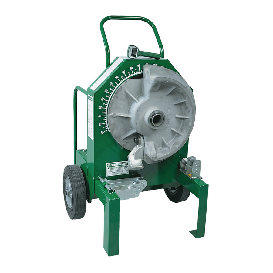
Temperature ... –20 C to 49 C (–5 F to 120 F) Relative Humidity ... 0 to 98% Capacity ... 1/2" to 2" conduit, schedule 40 pipe Greenlee Textron / Subsidiary of Textron Inc. ® Deluxe Electric Bender 555R Deluxe Electric Bender (shown) 6. -
Page 7: Bending Attachment Groups
Bending Shoe for 1-1/2" 23505 Bending Shoe for 2" 23541 Roller Support Unit for 1-1/2" to 2" 23818 Storage Box Greenlee Textron / Subsidiary of Textron Inc. ® Deluxe Electric Bender 26330: 1-1/2" to 2" IMC UPC No. 78-3310- 25263... -
Page 8: Setup
Note: 1-1/2" and 2" EMT and IMC bending shoes have only three drive studs. Installing a Bending Shoe Greenlee Textron / Subsidiary of Textron Inc. ® Deluxe Electric Bender 2. Mount the appropriate support unit onto the leg of the bender and install the hinge pin, as shown. -
Page 9: Operation
Loose clothing can get caught in moving parts. Failure to observe this warning can result in severe injury or death. Greenlee Textron / Subsidiary of Textron Inc. ® Deluxe Electric Bender BENDING CONDUIT 1. Plug the cord into an appropriate receptacle. See Grounding Instructions. - Page 10 • Do not allow the trailing end of the conduit to go over the roller supports. Failure to observe these warnings can result in severe injury or death. Greenlee Textron / Subsidiary of Textron Inc. ® Deluxe Electric Bender If bending any other size or type of conduit: a.
-
Page 11: Operation
DECREASE squeeze. Note: In order to distribute the load evenly, adjust both bolts to the same setting. See the illustration. 3. Tighten the set screws. Greenlee Textron / Subsidiary of Textron Inc. ® Deluxe Electric Bender Adjusting the Squeeze... -
Page 12: Illustrated Bending Glossary
Illustrated Bending Glossary Offset Height Greenlee Textron / Subsidiary of Textron Inc. ® Deluxe Electric Bender back-to-back bend — any U-shaped bend formed by two parallel 90 bends with a straight section of conduit or pipe between the bends. center-to-center distance — the distance between the successive bends that make up an offset or a three-bend saddle. -
Page 13: Bending Instructions
The rigid shoe can make a 180 bend in one shot. All other shoes bend to 90 maximum. STUB LENGTH MARK 2 MARK 1 DEDUCT MARK 2 Greenlee Textron / Subsidiary of Textron Inc. ® Deluxe Electric Bender Deduct Table SIZE DEDUCT Figures are approximate... -
Page 14: Bending Instructions
CENTER-TO-CENTER DISTANCE = OFFSET HEIGHT x MULTIPLIER OFFSET ANGLE 22-1/2 MULTIPLIER Figures are approximate X Table CONDUIT SIZE “X” 3-1/16 3-1/16 3-3/16 Figures are approximate Greenlee Textron / Subsidiary of Textron Inc. ® Deluxe Electric Bender MARK 1 HEIGHT 23-3/16 30-15/16 38-5/8 46-3/8 1-1/2 1-1/4 1-1/2... -
Page 15: Additional Bending Instructions
5. Bend the conduit. HEIGHT ANGLE MARK Greenlee Textron / Subsidiary of Textron Inc. ® Deluxe Electric Bender OFFSETS An offset is used to route the conduit around an ob- struction. To make an offset, two equal bends are required. -
Page 16: Three-Bend Saddle
5. Bend the conduit. LENGTH TO END OF SECOND BEND ANGLE LENGTH – Z MARK 1 Greenlee Textron / Subsidiary of Textron Inc. ® Deluxe Electric Bender THREE-BEND SADDLE 1. Select the size and type of conduit. Measure the height of the obstruction and the distance from the end of the conduit to the center (LENGTH TO CENTER) of the bend. - Page 17 SECTION HEIGHT L2 + STRAIGHT SECTION LENGTH – Z MARK 1 MARK 2 Greenlee Textron / Subsidiary of Textron Inc. ® Deluxe Electric Bender U-BENDS 1. Select the size and type of conduit. Determine the LENGTH and the HEIGHT. 2. Find the table that corresponds to the size and type of conduit selected in Step 1.
- Page 18 22.5 22.5 22.5 MINIMUM H = 1.94 MINIMUM H = 2.92 MINIMUM H = 5.27 MINIMUM H = 8.03 MINIMUM H = 13.95 Greenlee Textron / Subsidiary of Textron Inc. ® Deluxe Electric Bender 2" 4" 6" 8" 3.74 11.47 19.20...
- Page 19 22.5 22.5 22.5 MINIMUM H = 2.66 MINIMUM H = 4.09 MINIMUM H = 7.65 MINIMUM H = 11.92 MINIMUM H = 21.38 Greenlee Textron / Subsidiary of Textron Inc. ® Deluxe Electric Bender 2" 4" 6" 8" 1.35 9.07 16.80...
- Page 20 22.5 22.5 22.5 MINIMUM H = 3.28 MINIMUM H = 4.94 MINIMUM H = 8.95 MINIMUM H = 13.63 MINIMUM H = 23.74 Greenlee Textron / Subsidiary of Textron Inc. ® Deluxe Electric Bender 2" 4" 6" 8" 6.26 13.99 21.72...
- Page 21 22.5 22.5 22.5 MINIMUM H = 2.05 MINIMUM H = 3.06 MINIMUM H = 5.49 MINIMUM H = 8.31 MINIMUM H = 14.33 Greenlee Textron / Subsidiary of Textron Inc. ® Deluxe Electric Bender 2" 4" 6" 8" 3.03 10.76 18.48...
- Page 22 22.5 22.5 22.5 MINIMUM H = 2.88 MINIMUM H = 4.38 MINIMUM H = 8.06 MINIMUM H = 11.32 MINIMUM H = 21.96 Greenlee Textron / Subsidiary of Textron Inc. ® Deluxe Electric Bender 2" 4" 6" 8" 1.08 8.81 16.52...
- Page 23 22.5 22.5 22.5 MINIMUM H = 3.47 MINIMUM H = 5.20 MINIMUM H = 9.38 MINIMUM H = 14.25 MINIMUM H = 24.72 Greenlee Textron / Subsidiary of Textron Inc. ® Deluxe Electric Bender 2" 4" 6" 8" 5.87 13.59 21.32...
- Page 24 22.5 22.5 22.5 MINIMUM H = 3.20 MINIMUM H = 4.84 MINIMUM H = 8.80 MINIMUM H = 13.45 MINIMUM H = 23.53 Greenlee Textron / Subsidiary of Textron Inc. ® Deluxe Electric Bender 2" 4" 6" 8" 6.41 14.14 21.87...
-
Page 25: Handle Removal And Replacement
Handle Removal and Replacement The handle of the 555 is designed to be removable. This feature is convenient when performing complex bending, and makes it easy to replace a damaged handle. Removal 1. Place the bender in the upright position. -
Page 26: Maintenance
Remount the eccentric with the four bolts. 4. Slide the reductor in slotted mounting holes to retension the chain. Set tension with the eccentric cam. Greenlee Textron / Subsidiary of Textron Inc. ® Deluxe Electric Bender Eight Reductor Mounting Bolts... -
Page 27: Troubleshooting
Bends are underbent a few Too little squeeze on 1-1/2" or 2" degrees. EMT or IMC conduit. Unusual conduit characteristics. Greenlee Textron / Subsidiary of Textron Inc. ® Deluxe Electric Bender PROBABLE CAUSE POSSIBLE REMEDY Check supply voltage circuit operation. - Page 28 ® Deluxe Electric Bender Greenlee Textron / Subsidiary of Textron Inc. 4455 Boeing Dr., Rockford, IL 61109-2988 815/397-7070...
-
Page 29: Español
DELUXE 555 CÓDIGO DE SERIE ADV Lea y entienda todas las instrucciones y la información sobre seguridad que aparecen en este manual, antes de manejar esta herramienta o darle mantenimiento. 999 3753.0 © 2001 Greenlee Textron IM 1458 REV 1 5/01... -
Page 30: Descripción
Recubierta de PVC y Tubo Programa 40. Los grupos de zapatas se muestran en la sección “Grupos de Aditamentos para Plegado” en este manual. Además de la unidad 555, este manual también aplica a los siguientes modelos: • 555E (incluye accesorios para doblar Tubería de Metal Eléctrica) -
Page 31: Importante Información Sobre Seguridad
De no observarse esta advertencia pueden sufrirse graves lesiones o incluso la muerte. Greenlee Textron / Subsidiary of Textron Inc. ® Peligro de electrocución: • Conecte el cable de alimentación a un receptáculo de 120 voltios y 20 amperios únicamente en un... - Page 32 Desconecte la dobladora antes de cambiar los accesorios. Si se activa accidentalmente, podría ocasionar graves lesiones. Greenlee Textron / Subsidiary of Textron Inc. ® No lo utilice como escalón o escalera. • La tubería portacables se mueve rápidamente conforme se dobla.
-
Page 33: Instrucciones De Puesta A Tierra
20 amperios. De no observarse estas advertencias pueden sufrirse graves lesiones o incluso la muerte. Greenlee Textron / Subsidiary of Textron Inc. ® Esta herramienta debe estar puesta a tierra. Una puesta a tierra eléctrica proporcionará una trayectoria de menor resistencia para una corriente eléctrica si ocurriese un funcionamiento incorrecto o una avería. -
Page 34: Identificación
Temperatura ... -20 C a 49 C (–5 F a 120 F) Humedad relativa ... 0 a 98% Capacidad ... Tubería portacables de 1/2 pulg. a 2 pulg., tubo programa 40 Greenlee Textron / Subsidiary of Textron Inc. Dobladora Eléctrica Deluxe 555 ®... -
Page 35: Grupos De Aditamentos Para Plegado
Zapata de Plegado para 2 pulg. 23541 Unidad de Soporte de Rodillo para 1-1/2 pulg. a 2 pulg. 23818 Caja de Almacenamiento Greenlee Textron / Subsidiary of Textron Inc. 26330: IMC de 1-1/2 pulg. a 2 pulg. No. UPC Clave 78-3310- 25263... -
Page 36: Instalación
2 pulg. tienen únicamente tres birlos de impulsión. Instalación de una Zapata de Plegado Greenlee Textron / Subsidiary of Textron Inc. ® 2. Monte la unidad de soporte apropiada en la pata de la dobladora e instale el pasador de bisagra, tal como se muestra. -
Page 37: Operación
La vestimenta holgada puede quedar atrapada en partes movibles. De no observarse esta advertencia pueden sufrirse graves lesiones o incluso la muerte. Greenlee Textron / Subsidiary of Textron Inc. ® PLEGADO DE TUBERÍA PORTACABLES 1. Enchufe el cordón en el receptáculo apropiado. - Page 38 Suelte el interruptor conforme alcanza el ángulo de plegado deseado. d. Oprima BEND momentáneamente hasta que finalice el plegado. Greenlee Textron / Subsidiary of Textron Inc. ® • No permita que un plegado o un acoplador sobrepase los soportes de rodillo.
- Page 39 Aviso: A fin de distribuir la carga de manera uniforme, ajuste ambos pernos de igual forma. Vea la ilustración. 3. Apriete los tornillos de fijación. Greenlee Textron / Subsidiary of Textron Inc. ® Ajuste de la Compresión Ajuste de Compresión Normal...
-
Page 40: Glosario De Plegado Ilustrado
Dobladora Eléctrica Deluxe 555 Glosario de Plegado Ilustrado Offset Height Greenlee Textron / Subsidiary of Textron Inc. back-to-back bend plegado contiguo — cualquier plegado en forma de U formado por dos plegados paralelos de 90 con una sección recta de tubería portacables o tubo entre los plegados. -
Page 41: Instrucciones De Plegado
Todas las demás zapatas doblan a un máximo de 90 . LONGITUD DEL CODO MARCA 2 MARCA 1 DEDUCCIÓN MARCA 2 Greenlee Textron / Subsidiary of Textron Inc. ® Tabla de Deducción TAMAÑO RÍGIDO/PVC 7-1/2 DEDUCCIÓN EMT... - Page 42 COMPENSACIÓN MULTIPLICADOR Las cifras son aproximadas Tabla X TAMAÑO DE LA TUBERÍA PORTACABLES “X” 3-1/16 3-1/16 3-3/16 Las cifras son aproximadas Greenlee Textron / Subsidiary of Textron Inc. LONGITUD MARCA 1 ALTURA 23-3/16 30-15/16 38-5/8 46-3/8 1-1/2 1-1/4 1-1/2 8-1/2...
-
Page 43: Instrucciones De Plegado Adicionales
5. Doble la tubería portacables: ALTURA ÁNGULO MARCA Greenlee Textron / Subsidiary of Textron Inc. ® COMPENSACIONES Se utiliza una compensación para enrutar la tubería portacables alrededor del obstáculo. Para realizar una compensación, se requieren dos plegados iguales. La distancia entre dos plegados es la distancia centro a centro. - Page 44 ÁNGULO LONGITUD – Z MARCA 1 MARCA 2 Greenlee Textron / Subsidiary of Textron Inc. SILLA DE TRES PLEGADOS 1. Seleccione el tamaño y tipo de tubería portacables. Mida la altura del obstáculo y la distancia desde el extremo de la tubería portacables al centro (LONGITUD HACIA EL CENTRO) del plegado.
- Page 45 L2 + SECCIÓN RECTA LONGITUD – Z MARCA 1 MARCA 2 Greenlee Textron / Subsidiary of Textron Inc. PLEGADOS EN FORMA DE U 1. Seleccione el tamaño y tipo de tubería portacables. Determine la LONGITUD y la ALTURA. 2. Encuentre la tabla que corresponda al tamaño y tipo de tubería portacables seleccionada en el...
- Page 46 22,5 22,5 ALTURA MÍNIMA = 1,94 ALTURA MÍNIMA = 2,92 ALTURA MÍNIMA = 5,27 ALTURA MÍNIMA = 8,03 ALTURA MÍNIMA = 13,95 Greenlee Textron / Subsidiary of Textron Inc. 2 pulg. 4 pulg. 6 pulg. 8 pulg. 10 pulg. 3,74...
- Page 47 22,5 22,5 ALTURA MÍNIMA = 2,66 ALTURA MÍNIMA = 4,09 ALTURA MÍNIMA = 7,65 ALTURA MÍNIMA = 11,92 ALTURA MÍNIMA = 21,38 Greenlee Textron / Subsidiary of Textron Inc. 2 pulg. 4 pulg. 6 pulg. 8 pulg. 10 pulg. 1,35...
- Page 48 22,5 22,5 ALTURA MÍNIMA = 3,28 ALTURA MÍNIMA = 4,94 ALTURA MÍNIMA = 8,95 ALTURA MÍNIMA = 13,63 ALTURA MÍNIMA = 23,74 Greenlee Textron / Subsidiary of Textron Inc. 2 pulg. 4 pulg. 6 pulg. 8 pulg. 10 pulg. 6,26...
- Page 49 22,5 22,5 ALTURA MÍNIMA = 2,05 ALTURA MÍNIMA = 3,06 ALTURA MÍNIMA = 5,49 ALTURA MÍNIMA = 8,31 ALTURA MÍNIMA = 14,33 Greenlee Textron / Subsidiary of Textron Inc. 4 pulg. 6 pulg. 8 pulg. 10 pulg. 3,03 10,76 18,48...
- Page 50 22,5 22,5 ALTURA MÍNIMA = 2,88 ALTURA MÍNIMA = 4,38 ALTURA MÍNIMA = 8,06 ALTURA MÍNIMA = 11,32 ALTURA MÍNIMA = 21,96 Greenlee Textron / Subsidiary of Textron Inc. 2 pulg. 4 pulg. 6 pulg. 8 pulg. 10 pulg. 1,08...
- Page 51 22.5 22.5 ALTURA MÍNIMA = 3.47 ALTURA MÍNIMA = 5.20 ALTURA MÍNIMA = 9.38 ALTURA MÍNIMA = 14.25 ALTURA MÍNIMA = 24.72 Greenlee Textron / Subsidiary of Textron Inc. 2 pulg. 4 pulg. 6 pulg. 8 pulg. 10 pulg. 5.87 13.59...
- Page 52 22.5 22.5 ALTURA MÍNIMA = 3.20 ALTURA MÍNIMA = 4.84 ALTURA MÍNIMA = 8.80 ALTURA MÍNIMA = 13.45 ALTURA MÍNIMA = 23.53 Greenlee Textron / Subsidiary of Textron Inc. 2 pulg. 4 pulg. 6 pulg. 8 pulg. 10 pulg. 6.41 14.14...
-
Page 53: Extracción Y Reemplazo De La Empuñadura
Dobladora Eléctrica Deluxe 555 Extracción y Reemplazo de la Empuñadura La empuñadura del modelo 555 es desmontable. Esta característica es conveniente cuando se realizan tareas de plegado complicadas, y facilita el reemplazo de una empuñadura dañada. Extracción 1. Coloque la dobladora en posición vertical. -
Page 54: Mantenimiento
4. Deslice el reductor por los orificios de montaje ranurados para volver a tensar la cadena. Ajuste la tensión con la leva excéntrica.retension the chain. Set tension with the eccentric cam. Greenlee Textron / Subsidiary of Textron Inc. ® Ocho pernos de montaje... -
Page 55: Diagnóstico Y Solución De Fallas
EMT o IMC de 1-1/2 pulg. o 2 pulg. Características poco comunes de la tubería portacables. Greenlee Textron / Subsidiary of Textron Inc. CAUSA PROBABLE Verifique la operación del circuito del suministro de tensión. Verifique que el interruptor se encuentre encendido. - Page 56 ® Dobladora Eléctrica Deluxe 555 Greenlee Textron / Subsidiary of Textron Inc. 4455 Boeing Dr., Rockford, IL 61109-2988 815/397-7070...
-
Page 57: Français
ÉLECTRIQUE DE LUXE CODE DE SERIE ADV Nous vous conseillons de lire attentivement et de bien comprendre les instructions suivantes avant d’utiliser ou de procéder à l’entretien de cet outil. 999 3753.0 © 2001 Greenlee Textron IM 1458 REV 1 5/01... -
Page 58: Description
40. Les groupes de sabots sont illustrés dans la section des groupes d’outils de travail pour le cintrage de ce manuel. En plus due la 555, ce manuel s’applique également aux modèles suivants : • 555E (comprend les accessoires pour cintrer les tubes métalliques pour l’électricité) -
Page 59: Consignes De Sécurité Importantes
L’inobservation de cette consigne entraînera des blessures graves, voire mortelles. Greenlee Textron / Subsidiary of Textron Inc. ® Deluxe Cintreuse Electrique De Luxe 4455 Boeing Dr., Rockford, IL 61109-2988 815/397-7070 Risque d’électrocution : •... - Page 60 Débrancher la cintreuse avant de changer les accessoires. Un démarrage accidentel peut entraîner de graves blessures. Greenlee Textron / Subsidiary of Textron Inc. ® Deluxe Cintreuse Electrique De Luxe • Le tube se déplace rapidement lors du cintrage.
-
Page 61: Instructions De Mise À La Terre
L’inobservation de cette consigne peut entraîner des blessures graves, voire mortelles. Greenlee Textron / Subsidiary of Textron Inc. ® Deluxe Cintreuse Electrique De Luxe Cet outil doit être mis à la terre. Dans l’éventualité d’un mauvais fonctionnement ou d’une défaillance, une mise à... -
Page 62: Identification
Température ... -20 à 49 C (-5 à 120 F) Humidité relative ... 0 à 98 % Capacité ... tubes de 1/2 à 2 po, tuyauterie nomenclature 40 Greenlee Textron / Subsidiary of Textron Inc. ® Deluxe Cintreuse Electrique De Luxe Cintreuse électrique 555R de luxe (illustrée) -
Page 63: Groupe D'outils De Travail Pour Le Cintrage
Sabot de cintrage pour 2 po 23541 Support de rouleaux pour 1-1/2 à 2 po 23818 Boîte de rangement Greenlee Textron / Subsidiary of Textron Inc. ® Deluxe Cintreuse Electrique De Luxe 26330:1-1/2 à 2 po IMC N CUP Repère... -
Page 64: Installation
Remarque : Les sabots de cintrage EMT et IMC de 1-1/2 à 2 po ne comportent que trois ergots d’entraînement. Installation d’un sabot de cintrage Greenlee Textron / Subsidiary of Textron Inc. ® Deluxe Cintreuse Electrique De Luxe 2. Monter le support adéquat sur la jambe de la cintreuse et installer l’axe d’articulation, tel... - Page 65 Les vêtements lâches peuvent être happés par les parties mobiles. L’inobservation de cette consigne peut entraîner des blessures graves, voire mortelles. Greenlee Textron / Subsidiary of Textron Inc. ® Deluxe Cintreuse Electrique De Luxe CINTRAGE D’UN TUBE 1. Brancher le cordon dans la prise appropriée.
-
Page 66: Utilisation
L’inobservation de ces consignes peut entraîner des blessures graves, voire mortelles. Greenlee Textron / Subsidiary of Textron Inc. ® Deluxe Cintreuse Electrique De Luxe Cintrage de tout autre type de tube ou tuyau de nomenclature différente :... - Page 67 Remarque : Un réglage identique des deux boulons assure une distribution uniforme de la charge. Voir l’illustration. 3. Serrer les vis. Greenlee Textron / Subsidiary of Textron Inc. ® Deluxe Cintreuse Electrique De Luxe Réglage standard de la compression INCORRECT 4455 Boeing Dr., Rockford, IL 61109-2988 815/397-7070...
-
Page 68: Glossaire Illustré Sur Le Cintrage
Glossaire illustré sur le cintrage Offset Height Greenlee Textron / Subsidiary of Textron Inc. ® Deluxe Cintreuse Electrique De Luxe back-to-back bend cintrage bout à bout — tout cintrage en U formé par deux cintrages parallèles de 90 comportant une section droite de tube ou de tuyau entre les deux cintrages. -
Page 69: Instructions De Cintrage
90 . LONGUEUR D’EXTREMITE COUDEE MARQUE 2 DEDUCTION MARQUE 2 MARQUE 1 Greenlee Textron / Subsidiary of Textron Inc. ® Deluxe Cintreuse Electrique De Luxe Tableau des déductions DIAMETRE DEDUCTION EMT LONGUEUR MINIMALE DE L’EXTREMITE COUDEE = DEDUCTION PLUS 2 POUCES Les valeurs sont approximatives Tableau des échelles... - Page 70 MULTIPLICATEUR Les valeurs sont approximatives Tableau des X TAILLE DU TUBE “X” 3-1/16 3-1/16 3-3/16 Les valeurs sont approximatives Greenlee Textron / Subsidiary of Textron Inc. ® Deluxe Cintreuse Electrique De Luxe LONGUEUR MARQUE 1 HAUTEUR 23-3/16 30-15/16 38-5/8 46-3/8...
-
Page 71: Instructions Supplémentaire Sur Le Cintrage
à Y pouces de l’extrémité du tube. 5. Cintrer le tube. HAUTEUR ANGLE MARQUE Greenlee Textron / Subsidiary of Textron Inc. ® Deluxe Cintreuse Electrique De Luxe DECALAGES On utilise un décalage pour acheminer le tube autour d’un obstacle. Un décalage est le résultat de deux cintrages égaux. - Page 72 DU DEUXIEME CINTRAGE ANGLE LONGUEUR – Z MARQUE 1 MARQUE 2 Greenlee Textron / Subsidiary of Textron Inc. ® Deluxe Cintreuse Electrique De Luxe DOS D’ANE A TROIS CINTRAGES 1. Sélectionner le diamètre et le type de tube. Mesurer la hauteur de l’obstacle et la distance à partir de l’extrémité...
- Page 73 HAUTEUR L2 + SECTION DROITE LONGUEUR – Z MARQUE 1 MARQUE 2 Greenlee Textron / Subsidiary of Textron Inc. ® Deluxe Cintreuse Electrique De Luxe CINTRAGES EN U 1. Sélectionner le diamètre et le type de tube. Déterminer la LONGUEUR et la HAUTEUR.
- Page 74 22.5 22.5 H MINIMALE = 1,94 H MINIMALE = 2,92 H MINIMALE = 5,27 H MINIMALE = 8,03 H MINIMALE = 13,95 Greenlee Textron / Subsidiary of Textron Inc. ® Deluxe Cintreuse Electrique De Luxe 2" 4" 6" 8" 10"...
- Page 75 22.5 22.5 H MINIMALE = 2,66 H MINIMALE = 4,09 H MINIMALE = 7,65 H MINIMALE = 11,92 H MINIMALE = 21,38 Greenlee Textron / Subsidiary of Textron Inc. ® Deluxe Cintreuse Electrique De Luxe 2" 4" 6" 8" 10"...
- Page 76 22.5 22.5 H MINIMALE = 3,28 H MINIMALE = 4,94 H MINIMALE = 8,95 H MINIMALE = 13,63 H MINIMALE = 23,74 Greenlee Textron / Subsidiary of Textron Inc. ® Deluxe Cintreuse Electrique De Luxe 2" 4" 6" 8" 10"...
- Page 77 22.5 22.5 H MINIMALE = 2,05 H MINIMALE = 3,06 H MINIMALE = 5,49 H MINIMALE = 8,31 H MINIMALE = 14,33 Greenlee Textron / Subsidiary of Textron Inc. ® Deluxe Cintreuse Electrique De Luxe 2" 4" 6" 8" 10"...
- Page 78 22.5 22.5 H MINIMALE = 2,88 H MINIMALE = 4,38 H MINIMALE = 8,06 H MINIMALE = 11,32 H MINIMALE = 21,96 Greenlee Textron / Subsidiary of Textron Inc. ® Deluxe Cintreuse Electrique De Luxe 2" 4" 6" 8" 10"...
- Page 79 22.5 22.5 H MINIMALE = 3,47 H MINIMALE = 5,20 H MINIMALE = 9,38 H MINIMALE = 14,25 H MINIMALE = 24,72 Greenlee Textron / Subsidiary of Textron Inc. ® Deluxe Cintreuse Electrique De Luxe 2" 4" 6" 8" 10"...
- Page 80 22.5 22.5 H MINIMALE = 3,20 H MINIMALE = 4,84 H MINIMALE = 8,80 H MINIMALE = 13,45 H MINIMALE = 23,53 Greenlee Textron / Subsidiary of Textron Inc. ® Deluxe Cintreuse Electrique De Luxe 2" 4" 6" 8" 10"...
-
Page 81: Dépose Et Remplacement De La Poignée
Dépose et remplacement de la poignée La poignée de la 555 est conçue pour être amovible. Cette caractéristique est utile lors des cintrages com- plexes et facilite le remplacement d’une poignée endommagée. Dépose 1. Placer la cintreuse en position verticale. -
Page 82: Entretien
4. Faire glisser le réducteur dans les fentes de mon- tage pour rétablir la tension de la chaîne. Régler la tension avec la came à excentrique. Chaîne d’entraînement finale, numéro 60 HT Greenlee Textron / Subsidiary of Textron Inc. ® Deluxe Cintreuse Electrique De Luxe ® 634. -
Page 83: Dépannage
Compression trop faible pour un tube quelques degrés. EMT ou IMC de 1-1/2 à 2 PO. Caractéristiques anormales du tube. Greenlee Textron / Subsidiary of Textron Inc. ® Deluxe Cintreuse Electrique De Luxe CAUSE PROBABLE 4455 Boeing Dr., Rockford, IL 61109-2988 815/397-7070 ACTION CORRECTIVE Vérifier le fonctionnement du circuit... - Page 84 Greenlee Textron / Subsidiary of Textron Inc. 4455 Boeing Drive, Rockford, IL 61109-2988 USA Customer Service (International): 815/397-7070 • Fax: 815/397-9247 Customer Service (North America): 800/435-0786 • Fax: 800/451-2632, 815/397-1865 Canada Fax: 800/524-2853 Printed in the U.S.A.