Table of Contents
Advertisement
Quick Links
Advertisement
Table of Contents

Related Manuals for Cateye TR200DW280P


Summary of Contents for Cateye TR200DW280P
-
Page 3: Introduction
• No part of this manual may be reproduced or transmitted without the prior written permission of CatEye Co., Ltd. • The contents and illustrations in this manual are subject to change without notice. • If you have any questions or concerns about this manual, please contact CatEye at www.cateye.com. About the manuals... -
Page 4: Table Of Contents
Changing the computer configuration ........22 About the manuals ....... 1 File view (FILE VIEW) ..... 23 Proper use of the CatEye V2c ....3 Setting the clock/date Description of computer and its parts ..4 (CLOCK.DATE) ....... 27 Computer ......... 4 Wheel selection and tire Accessories ........ -
Page 5: Proper Use Of The Cateye V2C
Proper use of the CatEye V2c Observe the following instructions for safe usage. The meaning of icons in this manual: Warning!!! : Sections marked with these icons are critical for safe use of the device. Be sure to follow these instructions. -
Page 6: Description Of Computer And Its Parts
Description of computer and its parts Computer Front Back-light button (LT) Mode-1 button (M1/+) Mode-2 button (M2/-) Start / stop / enter button (SSE) Lap button (LAP) Back Battery cover All clear button (AC) Menu button (MENU) Accessories Bracket rubber pad Bracket / Speed sensor Bracket band... -
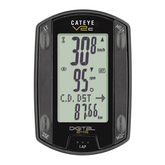
Page 7: Screen Display
Screen display : Speed pace arrow : Speed sensor signal Indicate Speed sensor signal status. The pace arrows show whether the cur- (page 14) rent speed is faster ( ) or slower ( ) than the average speed. : Alarm ... -
Page 8: How To Install The Unit On Your Bicycle
How to install the unit on your bicycle 1. Attach the bracket to the stem or handlebar The Flex Tight ™ bracket can be attached to either the stem or the handlebar depend- ing on how the bracket and band are configured. Caution: Tighten the dial on the bracket band by hand only. -
Page 9: Mount The Speed Sensor And Magnet
2. Mount the speed sensor and magnet Wheel magnet Speed sensor Cadence magnet Speed sensor 2-1. Temporarily secure the speed sensor Locate the speed sensor on the left chain stay as shown above, and loosely secure it with the nylon ties. * Do not tighten the nylon ties completely at this stage. -
Page 10: Remove/Install The Computer
2-3. Adjust the distance to the magnet 1. Adjust the distance between the wheel magnet and the SPEED side of the speed sensor to be about 3 mm. After adjustment, tighten the setscrew on the SPEED side. 2. Adjust the distance between the cadence About 3 mm magnet and the CADENCE side of the speed sensor to be about 3 mm. -
Page 11: Preparing The Computer
Preparing the computer Computer's basic items must be set up before using it. Removing the insulation sheet Close When using the unit for the first time after purchas- ing, open the battery cover and remove the insula- Insulation Open sheet tion sheet. -
Page 12: Formatting/Restarting Operation
1. Formatting/Restarting operation Formatting operation (At initial purchase, or reset all to default.) Caution: All data are reset to the default and deleted. 1. While pressing the MENU button on the back of the computer, press AC button. Release the MENU button when a test pattern is displayed on the screen. -
Page 13: Date/Clock Setting
2. Date/Clock setting Set the current date and time. 1. Select the date display format. Select the date display format from “YY/MM/DD”, “MM/DD/ YY”, and “DD/MM/YY” using the M1/+ and M2/- buttons, and confirm with the SSE button. Switch the display: M1/+ Confirm: (or) -
Page 14: Tire Circumference Input
3. Tire circumference input Enter the tire circumference of the bicycle wheel in millimeter. 1. Enter the last 2 digits of the tire circumference. Enter using the M1/+ and M2/- buttons, and move digits using the SSE button. Then, enter the first 2 digits in the same way. -
Page 15: Set The Sensor Id
4. Set the sensor ID Set the speed/cadence sensor ID. * This unit requres the sensor ID in order for the computer to receive signal from the sensors. * To set the sensor ID , be within 5 m from the bicycle with a speed/cadence sensor mounted properly (page 7). -
Page 16: Selecting Speed Unit
5. Selecting speed unit Select the speed unit from “km” and “mile”. 1. Select the speed unit. mile: M1/+ (or) M2/- 2. After selecting, press the MENU button. The measurement screen appears and the computer set-up is completed. 6. Operation test Test the functioning of the speed sensor (SPEED) and the cadence sensor (CADENCE). -
Page 17: Basic Operation Of The Computer
Basic operation of the computer Functions on the measurement screen The measurement screen displays 4 different types of data, which are switched by press- ing the M1/+ and M2/- buttons. The display data are as follows. Upper display data Displays the data related to the speed. Middle display data Displays the data related to the cadence. -
Page 18: Starting/Stopping The Measurement
Starting/Stopping the measurement Initially, the unit starts or stops measurement automatically in sync with the bicycle motion. This is called auto-mode function. “km/h” or “mph” flashes during measurement. The total distance, maximum speed, and maximum cadence are up- dated independently of stating/stopping measurement. Auto-mode function When the auto-mode is turned on ( lights up), the unit detects... -
Page 19: Measurement Screen
Measurement screen Upper and middle display data Current speed Displays the current speed. Updated every second. Cadence Displays the number of pedal rotations per minute. Updated every second. M1/+ Average speed Displays the average speed after the start of measurement. Average cadence Displays the average cadence after the start of measurement. -
Page 20: Lower Display Data
Lower display data Elapsed time Displays the elapsed time from the start of measurement to the 1/10 second. When it exceeds 99:59’59”, it repeats from 00’00”0. * When the elapsed time reaches 1 hour, the 1/10 second is not displayed. M2/- Trip distance Displays the trip distance from the start of measurement. -
Page 21: Pace Function
Pace function Current speed 2 types of pace arrow icons for the current speed and the cadence are displayed on the screen. These arrow icons indicate whether the current speed (cadence) is above or below the average speed (average cadence). : Appears when the current value is above the average. -
Page 22: Countdown Distance
Lap time and split time Start of The lap time displays elapsed time from the last measurement press of the LAP button. Lap time 1 Lap time 2 The split time displays the elapsed time from the start of measurement to the point LAP button is Split time 1 pressed. -
Page 23: Target Cadence Zone
Target cadence zone During measurement, on the screen displays the target cadence zone status. (constant) : The target zone is turned on. (flashing) : The current cadence is out of the zone. (off) : The target zone is set to off. Target cadence zone * The target cadence zone set from the menu screen “Setting the... -
Page 24: Changing The Computer Configuration
Changing the computer configuration Pressing the MENU button in the measurement screen switches to the menu screen. In the menu screen, you can view and delete the files saved, and view and change various configurations. * Use the M1/+ and M2/- to change menu items. * After changes are made, be sure to review the setting(s) and confirm by pressing the MENU button. -
Page 25: File View (File View)
File view The lap and measurement data are saved into a file automatically each time a ride is reset (Resetting Operation page 16) With the file view, you can review the past rides or delete data recorded. Measurement data to be recorded in a file The computer can record up to 14 files When 14 files (rides) are saved, the oldest one is deleted automatically. - Page 26 File number 2. Select the file using the M1/+ and M2/- buttons, and confirm with the SSE button. Number of laps used in a file M1/+ Switching the file number: (or) M2/- 3. Scroll through the data saved in each file by pressing the SSE button.
- Page 27 Viewing the lap data View the lap data in a file saved in the computer. Select the file number you want to view from the menu screen “File view” (page 23). 1. Press the LAP button to view the lap data contained in the File number file selected.
- Page 28 Deleting files Delete the file saved in the computer. You can select deleting only the file specified, or all files. Switch to the menu screen “File view” (page 23). 1. Simultaneously press the SSE button and the M1/+ or M2/- File number button to switch to the deleting screen.
-
Page 29: Setting The Clock/Date (Clock.date)
M2/- M1/+ Setting the clock/date Set the “Clock display format”, “Hour”, “Minute”, “Date display format”, “Year”, “Month” and “Day.” 1. Press the MENU button in the measurement screen to switch to the menu top screen. Switch to the CLOCK.DATE screen using the M1/+ and M2/- buttons, and confirm with the SSE button. -
Page 30: Wheel Selection And Tire Circumference (Wheel)
M2/- M1/+ Wheel selection and tire circumference Switch the Wheel Size (A / B), and change the Tire Size (tire roll out length). * For the tire size, see “Tire circumference” (page 12). Wheel selection 1. Press the MENU button in the measurement screen to switch to the menu top screen. - Page 31 1. Press the MENU button on the measurement screen to switch to the menu top screen. Switch to the SEnSOR-ID screen using the M1/+ and M2/- buttons, and confirm with the SSE button. Menu top: MENU (Back) M1/+ Changing the menu: Confirm: (or) M2/-...
-
Page 32: Setting The Measurement Unit (Unit)
M2/- M1/+ Setting the measurement unit Change the unit (km or mile). * Stop measurement and perform the resetting operation (page 16) before you change the unit. Unless you perform the resetting operation, “DATA RESET” appears on the screen, preventing from changing the unit. 1. -
Page 33: Setting The Auto-Mode (Auto Mode)
M2/- M1/+ 3. Pressing the MENU button returns to the menu top screen (ODO InPUT screen), and confirm the change(s). Pressing it again returns to the measurement screen. To the menu top/measurement screen: MENU (Back) Setting the auto-mode Switch on/off of the auto-mode (page 16). 1. -
Page 34: Setting Sound (Sound)
M2/- M1/+ 2. Enter the target distance using the M1/+ and M2/- buttons, and move digits using the SSE button. * The target distance can be set to the 0.1 km. M1/+ Increase/decrease: Move digits: (or) Ta r g e t d i s t a n c e M2/- In case of 100.0 km 3. -
Page 35: Setting The Target Cadence Zone (Cdc.zone)
M2/- M1/+ Setting the target cadence zone You can set the target cadence zone on/off and change the upper/lower limit of the target cadence zone. * Stop measurement and perform the resetting operation (page 16) before you can change the target cadence zone. Unless you perform the resetting operation, “DATA RESET”... -
Page 36: Use Of The Target Zone
Use of the target zone When the target cadence zone is turned On, cadence is monitored against set zone range. When the cadence is out of the zone during measurement, the computer sounds an alarm and notifies a rider by flashing For training aiming at a cadence of 80 to 120 rpm, set the lower limit to 80 and upper limit to 120. -
Page 37: Trouble Shooting
Trouble shooting If a malfunction occurs, check the following before contacting CatEye or your retailer for repair or service. Trouble on display Trouble Check Items Remedy Display motion be- Is the surrounding temperature Temperatures below freezing may re- comes slower. -
Page 38: Trouble On Operation
Trouble on operation Trouble Check Items Remedy Pressing the SSE button Check whether the auto- When illuminates, the auto-mode does not start/stop mode is turned on (with is on; you cannot start or stop mea- measurement. illuminating). surement by pressing the button. Turn off the auto-mode. -
Page 39: Replacing Battery
Replacing battery The product comes with factory-installed batteries. When a battery is empty, replace it with a new one according to the following instructions. Warning!!! : Safely dispose of the old batteries, and do not place them within reach of children. If a battery is swallowed, consult a doctor immediately. -
Page 40: Maintenance
Maintenance Perform the daily care according to the following instructions. • Regularly check that the positions of the magnets and sensors are correct, and they are secured firmly. • When the computer, and speed/cadence are dirty, wash them with water or wipe them with a soft cloth dampened with diluted neutral detergent, then wipe with dry cloth. -
Page 41: Specifications
Specifications Display Upper display Current speed 0.0 (4.0) 150.0 km/h [0.0 (3.0) 93.0 mph] functions For 27-inch tire size Average speed 0.0 - 150.0 km/h [0.0 - 93.0 mph] Maximum speed 0.0 (4.0) 150.0 km/h [0.0 (3.0) 93.0 mph] Middle display Cadence 0 (20) 199 rpm... -
Page 42: Registration
CatEye products are warranted to be free of defects from materials and workmanship for a period of two years from original purchase. If the product fails to work due to normal use, CatEye will repair or replace the defect at no charge. Service must be performed by CatEye or an authorized retailer.