Table of Contents
Advertisement
Quick Links
Installation, use and
maintenance manual
Rooftop Packaged Unit
Models:
UATYQ20ABAY1
UATYQ25ABAY1
UATYQ30ABAY1
UATYQ45ABAY1
UATYQ50ABAY1
UATYQ55ABAY1
UATYQ65ABAY1
UATYQ75ABAY1
UATYQ90ABAY1
UATYQ110ABAY1
UATYQ115ABAY1
UATYQ20AFC2Y1
UATYQ25AFC2Y1
UATYQ30AFC2Y1
UATYQ45AFC2Y1
UATYQ50AFC2Y1
UATYQ55AFC2Y1
UATYQ65AFC2Y1
UATYQ75AFC2Y1
UATYQ90AFC2Y1
UATYQ110AFC2Y1
UATYQ115AFC2Y1
UATYQ20AFC3Y1
UATYQ25AFC3Y1
UATYQ30AFC3Y1
UATYQ45AFC3Y1
UATYQ50AFC3Y1
UATYQ55AFC3Y1
UATYQ65AFC3Y1
UATYQ75AFC3Y1
Installation, use and maintenance manual
UATYQ90AFC3Y1
English
UATYQ110AFC3Y1
Rooftop Packaged Unit
UATYQ115AFC3Y1
Advertisement
Table of Contents

Related Manuals for Daikin UATYQ-AFC3Y1


Summary of Contents for Daikin UATYQ-AFC3Y1
- Page 1 Installation, use and maintenance manual Rooftop Packaged Unit Models: UATYQ20ABAY1 UATYQ25ABAY1 UATYQ30ABAY1 UATYQ45ABAY1 UATYQ50ABAY1 UATYQ55ABAY1 UATYQ65ABAY1 UATYQ75ABAY1 UATYQ90ABAY1 UATYQ110ABAY1 UATYQ115ABAY1 UATYQ20AFC2Y1 UATYQ25AFC2Y1 UATYQ30AFC2Y1 UATYQ45AFC2Y1 UATYQ50AFC2Y1 UATYQ55AFC2Y1 UATYQ65AFC2Y1 UATYQ75AFC2Y1 UATYQ90AFC2Y1 UATYQ110AFC2Y1 UATYQ115AFC2Y1 UATYQ20AFC3Y1 UATYQ25AFC3Y1 UATYQ30AFC3Y1 UATYQ45AFC3Y1 UATYQ50AFC3Y1 UATYQ55AFC3Y1 UATYQ65AFC3Y1 UATYQ75AFC3Y1 Installation, use and maintenance manual UATYQ90AFC3Y1 English UATYQ110AFC3Y1...
-
Page 3: Table Of Contents
Contents Introduction Conformity Description 1.2.1 Symbols 1.2.2 Labels Safety General safety precautions 2.1.1 Discharge of the safety valves Basic rules Noise levels Residual risks 2.5 Safety information on the refrigerant fluid 2.5.1 Hazards and health consequences Receiving the product and storage Reception Transport Handling Storage Product description Intended use Unintended use Control and safety devices Principles of operation Structure 4.6... - Page 4 Installation 5.3.1 Fitting of rain hoods 5.3.2 External positioning 5.3.3 Anti-vibration mounts 5.3.4 Minimum distances Electrical connections Condensate drain connections 5.5.1 Condensate drain of the internal air coil 5.5.2 Condensate drain of the external air coil Aeraulic connections 5.6.1 Return and supply ducts 5.6.2 Connection of the ducts Commissioning Preliminary operations First starting 6.2.1 Preliminary checks 6.2.2 Functional tests Calibration of safety components Checks during operation Alarms and malfunctions Temporary stop Stop for long periods of time...
- Page 5 THANK YOU Thank you for choosing our product. It is the result of many years’ experience and careful design and has been built with first-class quality materials and advanced technologies. Declaration or certificate of conformity also guarantees that the equipment meets the requirements of the European Machinery Safety Directive. The quality level is constantly monitored, and therefore our products are synonymous with Safety, Quality and Reliability. Changes considered necessary for product improvement may be made to the stated data at any time without any obligation to give prior notice.
-
Page 6: Introduction
INTRODUCTION 1.1 Conformity With regard to relevant regulations and directives, please see the declaration of conformity in the "document folder". 1.2 Description 1.2.1 Symbols A description of the main symbols used in this manual and on the labels affixed to the unit is given below. Danger symbol; take extreme care. Danger symbol; moving mechanical parts. Danger symbol; live parts. Warning symbol; important information Note symbol;... -
Page 7: Labels
1.2.2 Labels For the constructional features, technical data and available models, please refer to the technical catalogue. The model, serial number, features, power supply voltage and so on are shown on the labels affixed to the unit (the following illustrations are shown only as an example). The Manufacturer adopts a continuous development policy and, in this perspective, reserves the right to make changes and improvements to the documentation and to the units without prior notice. -
Page 8: Safety
SAFETY 2.1 General safety precautions A space of about 2 metres around the unit is identified as external danger zone. If the unit is positioned in an unprotected place that can be reached by unqualified persons, access to this area must be prohibited by special guarding. The equipment operator is responsible for complying with regulatory obligations. The equipment operator is the person who has actual control over the technical operation and free access, which means the possibility of monitoring its components and their operation and the possibility of granting access to third parties. The equipment operator has the power (including financial power) to decide on technical modifications, checks and repairs. The equipment operator may give instructions to employees or to external companies for carrying out maintenance and repair operations. Only an authorised operator should be able to access the unit. Installation and maintenance or repair of the unit must be carried out by personnel and companies holding a certificate issued by a certification body designated by a member state that certifies the requirements contained in Commission Regulation (EC) No. 517/2014. -
Page 9: Discharge Of The Safety Valves
In units with capacitors and/or inverters, certain components can remain live for several minutes even after having turned off the main switch. Wait 10 minutes before working on the electrical parts of the unit. Circuits supplied from external sources (made with orange cable) can remain live even after the power supply to the unit has been turned off. Work on the unit only if there is sufficient lighting for the type of work to be carried out. The law regulating the use of stratospheric ozone depleting substances prohibits the release of refrigerant gases into the environment and obliges owners to recover and return them to the dealer or take them to special collection centres at the end of their operational life. The refrigerant contained in the refrigerant circuit is included among the substances subject to special control regulations provided for by law and must therefore be disposed of as indicated above. -
Page 10: Basic Rules
2.2 Basic rules All the units are designed and built in compliance with Directive 2014/68/EU of the European Parliament and of the Council of 15 May 2014 on the approximation of the laws of the Member States relating to pressure equipment. To ensure maximum safety, in order to prevent possible risks, follow the instructions below: - this product contains pressurised vessels, live components, moving mechanical parts and very hot and cold surfaces that, in certain situations, can pose a risk: all maintenance work must be carried out by skilled personnel equipped with the necessary qualifications in accordance with current regulations. Before carrying out any operation, make sure that the personnel in charge has full knowledge of the documentation supplied with the unit. -
Page 11: Noise Levels
2.3 Noise levels The starting of the unit, with activation of its components, emits a sound whose intensity varies according to the operating level. Correct site choice and correct installation prevent the unit from causing an annoying sound due to resonances, reflections and vibrations. -
Page 12: Safety Information On The Refrigerant Fluid
2.5 Safety information on the refrigerant fluid This product contains fluorinated greenhouse gases included in the Kyoto protocol. Do not release these gases into the atmosphere. Type of refrigerant: R410A GWP value: 2088. GWP is the global warming potential. The quantity of refrigerant fluid is indicated in the unit’s data label. Periodic inspections are necessary to check for refrigerant fluid leaks in accordance with local and/or European regulations. 2.5.1 Hazards and health consequences If accidentally released, rapid evaporation of the liquid can cause freezing. In case of contact with the liquid: - defrost the various part with water; - remove clothing carefully; - rinse thoroughly with water. Contaminated clothing and shoes should be washed before reuse. -
Page 13: Receiving The Product And Storage
RECEIVING THE PRODUCT AND STORAGE 3.1 Reception On receiving the unit, check that it is undamaged, bearing in mind that it left the factory in perfect condition. Report any signs of damage immediately to the transporter and make a note of these on the Delivery Sheet before signing it. - Page 14 A pallet is secured under the unit so that it can also be unloaded and handled with a suitable forklift truck. If anti-vibration mounts are installed under the base of the unit, this must be done with the unit raised by no more than 200 mm from the ground and without putting any parts of the body under it.
-
Page 15: Storage
For the other sizes, the unit should be lifted using only and solely the lifting slings and tubes supplied with it. Fig. 3 Detail of hooking the sling to the lifting tube To prevent the slings from touching the unit, suitable protective devices must be placed on the upper edges. It is mandatory to use a lifting beam adjusted to the width of the unit in order to ensure lifting stability Fig. -
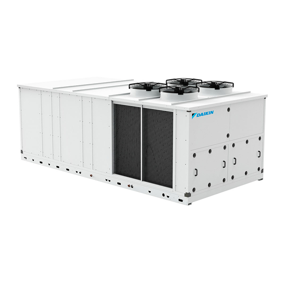
Page 16: Product Description
PRODUCT DESCRIPTION 4.1 Intended use These units are made for air cooling and heating, and are generally used in applications in the air conditioning field. These are high efficiency, self-contained air conditioners, for both summer and winter use, that allow complete thermo-hygrometric air handling to be achieved. They can be used in both commercial and industrial applications that, besides having load variability, can be characterized by high latent loads and need to guarantee optimum conditions for occupants. -
Page 17: Control And Safety Devices
4.3 Control and safety devices The unit is integrally managed by an electronic microprocessor control that, through the various installed temperature and pressure sensors, keeps its operation within the safety limits. All the parameters involved with control of the unit are shown in the “Operating Manual” that is an integral part of the documentation of the unit. -
Page 18: Air System
4.7 Air system 4.7.1 Internal air fans Depending on the configurations, there may be only supply fans or also return fans in the units. The fans are radial fans with reverse blades, with external rotor motor directly coupled to the impeller. The radial fans are called "EC", with electronically commutated brushless motor. The fan is powered by mains AC voltage, and speed control is obtained via DC 0-10V control signal coming from the microprocessor installed on the unit. This makes it possible to set the air flow rate through the parameter being displayed. -
Page 19: Dirty Filter Sensor
4.7.4 Dirty filter sensor The level of air filter clogging is checked by means of a differential pressure switch that measures the pressure drop between upstream and downstream of the filter. The control panel will signal, via an alarm on the display, the need to replace or clean the filter. The machine will continue to work in any case. The cut-in value is factory set and can be changed on the installed unit by turning the knob with graduated scale using a screwdriver. The fouling of the filter may cause a decrease in the flow rate and therefore of the machine’s performance; restoring the filter as quickly as possible from the time of reporting is recommended. 4.7.5 Air filters G4 The units are fitted with "G4" filters on the air supply side. To replace the filters, open the panel of the unit that shows the indication for access to the filters. -
Page 20: Programmable Control
4.7.6 Programmable control For some configurations and functionalities, a programmable control is used. The figure shows the main screen. Fig. 5 Programmable control display From the main screen, the "Prg" button is pressed to access the "Q0" screen of the "Menu" branch. 4.7.6.1 Switching the unit on/off To switch the unit on or off, from the "Q0" screen of the "Menu" branch, scroll the various selections of the branches using the arrow buttons until the unit "On/Off" selection appears highlighted. Confirm with the "enter" button to access the "N0" screen where the operating state of the unit is shown with the instruction for changing it. The unit can be switched on from the keypad depending on whether all the other OK signal inputs for starting are closed/enabled. -
Page 21: Wiring Diagram
4.8 Wiring diagram The wiring diagram is an essential part of the documentation and is present inside each unit. It is essential to refer to this document if you are unsure about anything or need further explanations regarding the auxiliary electrical connections and power connections as well as for the electrical specifications. In particular, refer to the wiring diagram as regards the possibility of remotely managing the functionalities that contemplate this. -
Page 22: Installation
INSTALLATION During installation or whenever work must be carried out on the unit, it is essential to strictly follow the instructions in this manual, comply with the directions on the unit and in any case take all necessary precautions. The pressures in the refrigerant circuit and the electrical components can create risky situations during installation and maintenance work. -
Page 23: Installation
5.3 Installation The units are sent from the factory already tested and they need only the electrical, aeraulic and hydraulic connections for installation. The only unassembled component shipped is the rain guard for units that envisage air exchange and are therefore equipped with external air damper. -
Page 24: External Positioning
5.3.2 External positioning A solid base on which to position the unit must be created. This base must be perfectly flat and horizontal. Its dimensions must be adequate for those of the unit. The slab must be: - made in a suitable foundation about 15-20 cm higher than the surrounding ground; - flat, horizontal and able to bear at least 4 times the operating weight of the unit; - at least 30 cm longer and wider than the unit. Although the units transmit low levels of vibration to the ground, it is advisable to lay a strip of hard rubber between the base frame and the support surface. -
Page 25: Minimum Distances
5.3.4 Minimum distances The service spaces to comply with are shown on the dimensional drawings attached to the documentation of the unit. It is essential to ensure an adequate volume of air on the suction and delivery side of the condensing coil. It is very important to avoid recirculation between suction and delivery, as this would lower the performance of the unit or even stop its normal operation. -
Page 26: Electrical Connections
5.4 Electrical connections All electrical operations must be carried out by personnel having the necessary legal requirements, and trained and informed on the risks connected with these operations. The sizing and characteristics of the power lines and relevant components must be determined by staff qualified to design electrical systems, following the international and national regulations of the place of installation of the units in conformity with the regulations in force at the time of installation. To install components outside the unit, you must refer to the wiring diagram supplied with the unit. - Page 27 The cross-section of the cable and the line protection devices must correspond to those indicated in the wiring diagram. The connections to the electrical control panel must be made maintaining the stated IP protection rating. If you use a residual current device to protect the power line, in units with inverter, use type "B" or "B+" residual current devices, with minimum tripping threshold of 300 mA and delayed tripping.
-
Page 28: Condensate Drain Connections
5.5 Condensate drain connections All units are fitted with a condensate collection tray at the base of the finned air handling coil for the purpose of collecting the condensate that forms during normal operation in cooling mode. Units operating in heat pump mode also have a condensate collection tray situated at the base of the source finned coil for the purpose of collecting the condensate that forms during operation in heating mode and the water that forms from frost during the defrost cycles. -
Page 29: Aeraulic Connections
5.6 Aeraulic connections 5.6.1 Return and supply ducts The units have provision for various connections of both the return duct and the supply duct. To identify these, refer to the dimensional drawing present in the documentation of the unit. For the connection, the closing panels with which the unit was shipped must be removed. Fig. -
Page 30: Commissioning
COMMISSIONING 6.1 Preliminary operations The unit should only be started up by qualified personnel authorised by the manufacturer. All the units are pre-charged with refrigerant gas, so the refrigerant circuit is pressurised. Check: - that the electrical connection has been made correctly and that all terminals are properly tightened; - that the voltage on the RST terminals is 400 V ± 10% (or the rated voltage of the unit if there are special voltages); - that the gas pressure in the refrigerant circuits is shown on the pressure gauges (if present) or on the control display;... -
Page 31: First Starting
6.2 First starting 6.2.1 Preliminary checks To operate, the unit must have the external OK signal input closed. Refer to the wiring diagram supplied with the unit for connection of the external OK signal input. If it is not necessary for system requirements, the external OK signal input must be short-circuited. 6.2.2 Functional tests The main ventilation system will start a few seconds after the unit has started. The starting of the compressors depends on the thermoregulation request and on possible activation of the air exchange on starting the washing function. -
Page 32: Calibration Of Safety Components
6.3 Calibration of safety components Any work on the unit must be carried out by qualified authorised personnel. Incorrect calibration values can cause serious damage to the unit and harm people. The control and safety equipment is calibrated and tested in the factory before the unit is shipped. However, after the unit has been started, the safety devices must be checked (only the high and low pressure switches). The checks must be carried out as described in the "Periodic checks" chapter. The calibration values are shown in the table Control and safety Activation set... -
Page 33: Checks During Operation
6.4 Checks during operation With the circuits operating at 100% and stable at working conditions near the nominal ones, check: - that the electrical absorption of the unit is close to the data shown in the wiring diagram. Considerably different values may be due to the reduced capacity operation of the unit, to working conditions very different from the nominal ones or to the malfunctioning of one or more components. - that the difference between the condensing temperature of each circuit and that of the air is less than 25°C. If it is greater, check that all the fans involved are turning correctly and that there are no obstructions or dirt on the surface of the condensing coil;... -
Page 34: Alarms And Malfunctions
6.5 Alarms and malfunctions Possible malfunctions will trigger the protective devices and safety devices of the unit before serious faults occur. All the “warnings” and “alarms” are recorded in the memory of the control and displayed on the display of the unit. Before resetting an alarm, the cause that triggered it must be found and eliminated. -
Page 35: Temporary Stop
6.6 Temporary stop The shutdown of the unit for a few days is considered as temporary. The unit must be stopped using the display of the control, the external OK signal or via serial if included. During the temporary stop, the unit must be powered correctly. When the temporary stop is carried out in this way, all that needs to be done to restart the unit is to set the control to “ON”. -
Page 36: Maintenance
MAINTENANCE All the operations described in this chapter must always be carried out by qualified and authorised personnel. Before carrying out any work on the unit or accessing internal parts, make sure you have turned off the power supply to it. The compressors and delivery pipes are very hot. Be particularly careful when working near them. Be particularly careful when working near the finned coils as the aluminium fins are very sharp. Do not access moving parts without guards. In units with capacitors and/or inverters, certain components can remain live for several minutes even after having turned off the main switch. Wait 10 minutes before working on the electrical parts of the unit. Circuits supplied from external sources (made with orange cable) can remain live even after the power supply to the unit has been turned off. -
Page 37: External Cleaning
7.2 External cleaning The component of the unit that needs most care is the finned pack heat exchanger. It is essential to keep it clean and free of dirt and/or deposits that can hinder or prevent air flow. Regular cleaning of the surface of the coil is essential for the unit to work correctly and also increases the operating life of the exchanger and the unit. Frequent and correct cleaning of the coils contributes to considerably reducing corrosion. While cleaning the finned pack heat exchanger, the electrical control panel must be closed and the main disconnect switch must be locked in the "OFF" position. Using a jet of water on the coil while it is still dirty will cause deposits and pollutants to remain inside the exchanger, which will make cleaning even more difficult. All the dirt and deposits must therefore be removed from the surface before rinsing. -
Page 38: Internal Cleaning
7.3 Internal cleaning It is essential to keep the installation site clean and tidy for correct maintenance of the unit and to keep it in good working order. 7.3.1 Cleaning the unit Keep the inside of the electrical control panel and the compressor compartment clean. After working on the unit, always clean the electrical control panel of any work remnants and extraneous components. -
Page 39: Periodic Checks
7.4 Periodic checks Carry out periodic checks to make sure the unit is working correctly: RECOMMENDED OPERATION FREQUENCY Check the operation of all the control and safety equipment as described previously. Monthly Check the tightness of the electrical terminals in the electrical control panel and in the terminal boards of the compressors. The moving and fixed contacts of the contactors must be cleaned Monthly periodically and should be replaced whenever they show signs of deterioration. Check the refrigerant charge through the liquid sight glass. -
Page 40: Unscheduled Maintenance
7.5 Unscheduled maintenance After correctly starting-up and carrying out the relevant checks, the units normally do not need any intervention by the customer service in order to check the charge of the refrigerant gas. 7.5.1 Special work Over time, small leaks allowing the refrigerant gas to escape could be generated, so partially draining the circuit and causing malfunctioning of the unit. -
Page 41: Decommissioning
DECOMMISSIONING The units are marked with the following symbol: This means that electrical and electronic products cannot be mixed with general household waste. DO NOT attempt to dismantle the unit yourself: the work of dismantling the unit and treating the refrigerant, oil and other components must be carried out by an authorized installer and must meet applicable legislation. - Page 44 4P522680-1 2018.03...