Table of Contents
Advertisement
Quick Links
www.ti.com
User's Guide
BQ25181 EVM User's Guide
This user's guide provides detailed testing instructions for the BQ25181 evaluation module (EVM). Also included
are descriptions of the necessary equipment, equipment setup, procedures, the printed-circuit board layouts,
schematics, and the bill of materials (BOM).
Throughout this user's guide, the abbreviation EVM, BQ25181EVM, and the term evaluation module are
synonymous with the BQ25181 evaluation module, unless otherwise noted.
1
Introduction.............................................................................................................................................................................3
1.1 Features.............................................................................................................................................................................
1.2 EVM Setup.........................................................................................................................................................................
Procedures.................................................................................................................................................................6
3.1 Equipment..........................................................................................................................................................................
3.2 Charge Mode.....................................................................................................................................................................
3.3 Ship Mode..........................................................................................................................................................................
3.4 Shutdown Mode...............................................................................................................................................................
4 Layout....................................................................................................................................................................................
5
Schematics............................................................................................................................................................................14
6 Bill of Materials.....................................................................................................................................................................
Connections......................................................................................................................................................4
Figure 3-1. BQ25181EVM Connections......................................................................................................................................
Figure 3-2. TI Charger GUI Device Selection..............................................................................................................................
Figure 3-3. BQ25181EVM Connected.........................................................................................................................................
Figure 3-4. BQ25181EVM GUI Quick Start.................................................................................................................................
Figure 3-6. SHIP_RST Register: Enabling Ship Mode................................................................................................................
Figure 3-9. SHIP_RST Register: Long Press Action to Enable Shutdown Mode......................................................................
Figure 4-1. Top Overlay.............................................................................................................................................................
Figure 4-2. Top Solder...............................................................................................................................................................
Layer.................................................................................................................................................................13
Figure 4-4. Bottom Layer...........................................................................................................................................................
Solder..........................................................................................................................................................13
ABSTRACT
Table of Contents
Points..........................................................................................................................................5
List of Figures
Map.............................................................................................................................................8
Mode......................................................................................................11
Copyright © 2022 Texas Instruments Incorporated
Caution
Mode...............................................................................10
Table of Contents
Caution hot surface
Contact can cause burns
Do not touch!
Some components may reach high
temperatures >55°C when the board is
powered on. The user must not touch
the board at any point during operation
or immediately after operating, as high
temperatures may be present.
BQ25181 EVM User's Guide
3
3
6
6
9
10
13
17
6
7
7
8
9
11
13
13
13
1
Advertisement
Table of Contents

Related Manuals for Texas Instruments BQ25181


Summary of Contents for Texas Instruments BQ25181
-
Page 1: Table Of Contents
BQ25181 EVM User's Guide ABSTRACT This user's guide provides detailed testing instructions for the BQ25181 evaluation module (EVM). Also included are descriptions of the necessary equipment, equipment setup, procedures, the printed-circuit board layouts, schematics, and the bill of materials (BOM). - Page 2 Table 2-1. Jumper Default Configuration............................. Table 2-2. Test Point Descriptions............................... Table 6-1. Bill of Materials................................17 Trademarks All trademarks are the property of their respective owners. BQ25181 EVM User's Guide SLUUCL3 – APRIL 2022 Submit Document Feedback Copyright © 2022 Texas Instruments Incorporated...
-
Page 3: Introduction
The BQ25181EVM is an evaluation kit for the BQ25181 battery charge management IC. The BQ25181 is an I controlled, 1-A linear battery charger with Power Path in a small QFN package with a thermal pad. The BQ25181 integrates the most common functions for industrial and personal electronics applications and provides ultra-low IQ, integrated protections, programmability, TS monitoring, and best thermal performance in a small solution size. -
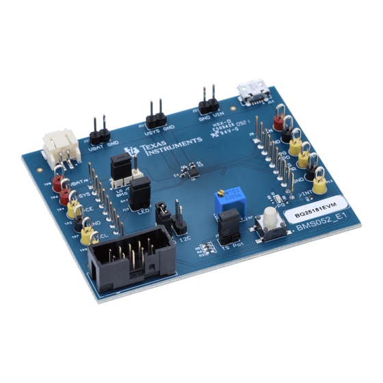
Page 4: Figure 1-1. Evm Connections
Input current range (IN to SYS) IBAT Battery discharge current (BAT to SYS) Operating ambient temperature range °C Operating junction temperature range °C BQ25181 EVM User's Guide SLUUCL3 – APRIL 2022 Submit Document Feedback Copyright © 2022 Texas Instruments Incorporated... -
Page 5: Evm Connectors And Test Points
IC VBAT test point IC SDA test point TP10 IC /PG or GPO test point TP11 IC TS/MR test point TP12 IC /INT test point SLUUCL3 – APRIL 2022 BQ25181 EVM User's Guide Submit Document Feedback Copyright © 2022 Texas Instruments Incorporated... -
Page 6: Testing Procedures
Figure 3-1. BQ25181EVM Connections To adjust the charge current or change other parameters, connect the USB2ANY to the EVM and then startup the TI Charger GUI. BQ25181 EVM User's Guide SLUUCL3 – APRIL 2022 Submit Document Feedback Copyright © 2022 Texas Instruments Incorporated... -
Page 7: Figure 3-2. Ti Charger Gui Device Selection
Testing Procedures Figure 3-2. TI Charger GUI Device Selection Select BQ25181 from the charger selection. Click Quick Start or Register Map. Figure 3-3. BQ25181EVM Connected The Quick Start is shown in Figure 3-4. Disabling the charge through I C will override the charge disable pin. -
Page 8: Figure 3-4. Bq25181Evm Gui Quick Start
Testing Procedures www.ti.com Figure 3-4. BQ25181EVM GUI Quick Start The register map is shown in Figure 3-5. Figure 3-5. BQ25181 Register Map BQ25181 EVM User's Guide SLUUCL3 – APRIL 2022 Submit Document Feedback Copyright © 2022 Texas Instruments Incorporated... -
Page 9: Ship Mode
After holding the button SW1 for longer than MR_LPRESS (default: 2b01 (10s), the voltage on SYS (SC #3) will fall to 0 V. SLUUCL3 – APRIL 2022 BQ25181 EVM User's Guide Submit Document Feedback Copyright © 2022 Texas Instruments Incorporated... -
Page 10: Shutdown Mode
(0x09) to 2b01. You will know you are in Shutdown Mode as the voltage on the SYS pin (SC #2) will fall to 0 V and the voltage on the TS/MR pin falls to 0 V. BQ25181 EVM User's Guide SLUUCL3 – APRIL 2022 Submit Document Feedback Copyright © 2022 Texas Instruments Incorporated... -
Page 11: Figure 3-8. Ship_Rst Register: Enabling Shutdown Mode
Shutdown Mode. After holding the button SW1 for longer than MR_LPRESS (default: 2b01 (10s), the voltage on SYS (SC #3) will fall to 0 V. Figure 3-9. SHIP_RST Register: Long Press Action to Enable Shutdown Mode SLUUCL3 – APRIL 2022 BQ25181 EVM User's Guide Submit Document Feedback Copyright © 2022 Texas Instruments Incorporated... - Page 12 Testing Procedures www.ti.com To exit Ship Mode, simply turn on VIN at 5 V. Exiting Shutdown Mode will enable the VSYS output. BQ25181 EVM User's Guide SLUUCL3 – APRIL 2022 Submit Document Feedback Copyright © 2022 Texas Instruments Incorporated...
-
Page 13: Layout
Figure 4-2. Top Solder Figure 4-1. Top Overlay Figure 4-3. Top Layer Figure 4-4. Bottom Layer Figure 4-5. Bottom Solder Figure 4-6. Bottom Overlay SLUUCL3 – APRIL 2022 BQ25181 EVM User's Guide Submit Document Feedback Copyright © 2022 Texas Instruments Incorporated... -
Page 14: Schematics
Schematics www.ti.com 5 Schematics Figure 5-1 through Figure 5-3 illustrate the EVM schematics. Figure 5-1. BQ25181EVM Schematic BQ25181 EVM User's Guide SLUUCL3 – APRIL 2022 Submit Document Feedback Copyright © 2022 Texas Instruments Incorporated... -
Page 15: Figure 5-2. Bq25181Evm Jumper Connectors
Schematics Figure 5-2. BQ25181EVM Jumper Connectors SLUUCL3 – APRIL 2022 BQ25181 EVM User's Guide Submit Document Feedback Copyright © 2022 Texas Instruments Incorporated... -
Page 16: Figure 5-3. Ldo For Other Peripherals
Schematics www.ti.com Figure 5-3. LDO for Other Peripherals BQ25181 EVM User's Guide SLUUCL3 – APRIL 2022 Submit Document Feedback Copyright © 2022 Texas Instruments Incorporated... -
Page 17: Bill Of Materials
W x 0.200" H - 10,000 per inch roll RES, 10.0 k, 1%, 0.063 R1, R2, R11, R14 10.0k 0402 RC0402FR-0710KL Yageo America W, 0402 SLUUCL3 – APRIL 2022 BQ25181 EVM User's Guide Submit Document Feedback Copyright © 2022 Texas Instruments Incorporated... - Page 18 Fiducial mark. There is FID1, FID2, FID3 nothing to buy or mount. RES, 10.0 k, 1%, 0.063 10.0k 0402 RC0402FR-0710KL Yageo America W, 0402 BQ25181 EVM User's Guide SLUUCL3 – APRIL 2022 Submit Document Feedback Copyright © 2022 Texas Instruments Incorporated...
- Page 19 STANDARD TERMS FOR EVALUATION MODULES Delivery: TI delivers TI evaluation boards, kits, or modules, including any accompanying demonstration software, components, and/or documentation which may be provided together or separately (collectively, an “EVM” or “EVMs”) to the User (“User”) in accordance with the terms set forth herein.
- Page 20 www.ti.com Regulatory Notices: 3.1 United States 3.1.1 Notice applicable to EVMs not FCC-Approved: FCC NOTICE: This kit is designed to allow product developers to evaluate electronic components, circuitry, or software associated with the kit to determine whether to incorporate such items in a finished product and software developers to write software applications for use with the end product.
- Page 21 www.ti.com Concernant les EVMs avec antennes détachables Conformément à la réglementation d'Industrie Canada, le présent émetteur radio peut fonctionner avec une antenne d'un type et d'un gain maximal (ou inférieur) approuvé pour l'émetteur par Industrie Canada. Dans le but de réduire les risques de brouillage radioélectrique à...
- Page 22 www.ti.com EVM Use Restrictions and Warnings: 4.1 EVMS ARE NOT FOR USE IN FUNCTIONAL SAFETY AND/OR SAFETY CRITICAL EVALUATIONS, INCLUDING BUT NOT LIMITED TO EVALUATIONS OF LIFE SUPPORT APPLICATIONS. 4.2 User must read and apply the user guide and other available documentation provided by TI regarding the EVM prior to handling or using the EVM, including without limitation any warning or restriction notices.
- Page 23 Notwithstanding the foregoing, any judgment may be enforced in any United States or foreign court, and TI may seek injunctive relief in any United States or foreign court. Mailing Address: Texas Instruments, Post Office Box 655303, Dallas, Texas 75265 Copyright © 2019, Texas Instruments Incorporated...
- Page 24 TI products. TI’s provision of these resources does not expand or otherwise alter TI’s applicable warranties or warranty disclaimers for TI products. TI objects to and rejects any additional or different terms you may have proposed. IMPORTANT NOTICE Mailing Address: Texas Instruments, Post Office Box 655303, Dallas, Texas 75265 Copyright © 2022, Texas Instruments Incorporated...