Table of Contents
Advertisement
DECLARATION OF CONFORMITY
Per FCC Part 2 Section 2. 1077(a)
Responsible Party Name: G.B.T. INC.
Address: 18305 Valley Blvd., Suite#A
LA Puent, CA 91744
Phone/Fax No: (818) 854-9338/ (818) 854-9339
hereby declares that the product
Product Name:
Mother Board
GA-7IXE4
Model Number:
Conforms to the following specifications:
FCC Part 15, Subpart B, Section 15.107(a) and Section 15.109(a),
Class B Digital Device
Supplementary Information:
This device complies with part 15 of the FCC Rules. Operation is subject to the
following two conditions:
(1)
This device may not cause harmful
and
(2)
this device must accept any inference received, including
that may cause undesired operation.
Representative Person's Name:
ERIC LU
Eric Lu
Signature:
Date:
Jul. 4, 2000
determined by turning the equipment off and on, the user is encouraged to try to
correct the interference by one or more of the following measures:
-Reorient or relocate the receiving antenna
-Move the equipment away from the receiver
-Plug the equipment into an outlet on a circuit different from that to which
the receiver is connected
-Consult the dealer or an experienced radio/television technician for
additional suggestions
You are cautioned that any change or modifications to the equipment not
expressly approve by the party responsible for compliance could void Your
authority to operate such equipment.
This device complies with Part 15 of the FCC Rules. Operation is subjected to
the following two conditions 1) this device may not cause harmful interference
and 2) this device must accept any interference received, including interference
that may cause undesired operation.
FCC Compliance Statement:
This equipment has been tested and found to
comply with limits for a Class B digital device,
pursuant to Part 15 of the FCC rules. These
limits are designed to provide reasonable
protection
against
residential
installations.
generates,
uses,
frequency energy, and if not installed and used
in accordance with the instructions, may cause
harmful interference to radio communications.
However, there is no guarantee that interference
will not occur in a particular installation. If this
equipment does cause interference to radio or
television equipment reception, which can be
harmful
interference
This
equipment
and
can
radiate
in
radio
Advertisement
Chapters
Table of Contents

Related Manuals for Gigabyte GA-7IXE4


Summary of Contents for Gigabyte GA-7IXE4
- Page 1 LA Puent, CA 91744 Phone/Fax No: (818) 854-9338/ (818) 854-9339 hereby declares that the product Product Name: Mother Board GA-7IXE4 Model Number: Conforms to the following specifications: FCC Part 15, Subpart B, Section 15.107(a) and Section 15.109(a), Class B Digital Device Supplementary Information: This device complies with part 15 of the FCC Rules.
-
Page 2: Declaration Of Conformity
Safety of household and similar electrical appliances (Stamp) Declaration of Conformity We, Manufacturer/Importer (full address) G.B.T. Technology Träding GMbH declare that the product Mother Board GA-7IXE4 is in conformity with EN 61000-3-2* EN60555-2 EN61000-3-3* EN60555-3 EN 50081-1 EN 50082-1 EN 55081-2... - Page 3 7IXE4 Athlon AGP Motherboard USER'S MANUAL Athlon Processor Motherboard REV. 1.0 Fourth Edition R-10-04-010615...
- Page 4 How This Manual Is Organized This manual is divided into the following sections: 1) Revision List 2) Item Checklist 3) Features 4) Hardware Setup 5) Performance & Block Diagram 6) BIOS Setup 7) Appendix Manual revision information Product item list Product information &...
-
Page 5: Table Of Contents
Revision History Item Checklist Summary of Features 7IXE4 Motherboard Layout Page Index for Connectors / Panel and Jumper Definition Performance List Block Diagram Memory Installation Page Index for BIOS Setup Appendix Table Of Content P.20 P.21 P.22 P.23 P.55... -
Page 7: Revision History
7IXE4 Motherboard Revision History Revision Revision Note Initial release of the 7IXE4 motherboard user’s manual. Second release of the 7IXE4 motherboard user’s manual. Third release of the 7IXE4 motherboard user’s manual. Fourth release of the 7IXE4 motherboard user’s manual. The author assumes no responsibility for any errors or omissions that may appear in this document nor does the author make a commitment to update the information contained herein. -
Page 8: Item Checklist
Item Checklist Item Checklist The 7IXE4 Motherboard Cable for IDE / Floppy device Diskettes or CD (TUCD) for motherboard utilities Internal COM B Cable (Optional) Internal USB Cable (Optional) Cable for SCSI device 7IXE4 User’s Manual... -
Page 9: Summary Of Features
7IXE4 Motherboard Summary Of Features Form factor Chipset AMD 750, consisting of: Clock Generator Memory I/O Control Slots On-Board IDE Hardware Monitor (Optional) On-Board Peripherals PS/2 Connector BIOS 30.4 cm x 22 cm ATX SIZE form factor, 4 layers PCB. K7) Socket A Processor Athlon ( 256K/64K 2... - Page 10 Summary of Features Additional Features Internal/External Modem Wake up Keyboard Password Wake up Mouse Wake up LAN Wake up System after AC back...
-
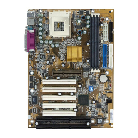
Page 11: 7Ixe4 Motherboard Layout
7IXE4 Motherboard 7IXE4 Motherboard Layout PS/2 Socket A CPU JP10 JP15 PCI1 PCI2 PCI3 PCI4 PCI5 ISA1 ISA2 AMD751 7IXE4 AMD756 Battery JP13 BIOS JP12... - Page 12 Page Index for CPU Speed Setup / Connectors / Panel and Jumper Definition CPU Speed Setup Connectors COM A / COM B / LPT Port USB Connector PS/2 Keyboard & PS/2 Mouse Connector JP2 (Power Fan) J9 (CPU Fan) J6 (System Fan) ATX Power Floppy Port IDE 1(Primary) / IDE 2(Secondary) Port...
-
Page 13: Cpu Speed Setup
7IXE4 Motherboard CPU Speed Setup The system bus frequency can be switched at 90MHz, 95MHz, 100MHz, 105MHz, 110MHz and 115MHz by adjusting SW1 (See Figure 1). The CPU speed must match with the frequency RATIO. It will cause system hanging up if the frequency RATIO is higher than that of CPU. -
Page 14: Connectors
Connectors COM A / COM B / LPT Port USB Connector LPT Port COM B COM A Pin No. Definition USB V0 USB D0- USB D0+ 1 2 3 4 USB V1 USB D1- USB D1+ Connectors... -
Page 15: Ps/2 Keyboard & Ps/2 Mouse Connector
7IXE4 Motherboard PS/2 Keyboard & PS/2 Mouse Connector JP2: Power Fan PS/2 Mouse PS/2 Mouse/ Keyboard Pin No. PS/2 Keyboard Pin No. Definition +12V SENSE Definition Data VCC(+5V) Clock... -
Page 16: J9: Cpu Fan
J9: CPU Fan J6: System Fan Pin No. Definition +12V SENSE Pin No. Definition +12V SENSE Connectors... -
Page 17: Atx Power
7IXE4 Motherboard ATX Power Floppy Port Pin No. 3,5,7,13,15-17 1,2,11 4,6,19,20 5V SB stand by+5V PS-ON(Soft On/Off) Red Line Definition 3.3V +12V -12V Power Good... -
Page 18: Ide1 (Primary), Ide2 (Secondary) Port
IDE1 (Primary), IDE2 (Secondary) Port USB Port Red Line IDE 1 IDE 2 Pin No. Definition USB D0 USB D0+ USB D1 USB D1+ Connectors... -
Page 19: Ir [Optional]
7IXE4 Motherboard IR: Infrared Connector (Optional) JP9: Ring Power On (Internal Modem Card Wake Up) Pin No. Definition VCC (+5V) IR Data Input IR Data Output Pin No. Definition Signal... -
Page 20: Jp4: Wake On Lan
JP4: Wake On LAN J30: HDT Herder Connector (For testing purpose only) Pin No. Definition +5VSB Signal Connectors... -
Page 21: Panel And Jumper Definition
7IXE4 Motherboard Panel And Jumper Definition J22: For 2x11 Pins Jumper GN (Green Switch) GD (Green LED) HD (IDE Hard Disk Active LED) SPK (Speaker Connector) RE (Reset Switch) P+P P (Power LED) PW (Soft Power Connector) Open: Normal Operation Close: Entering Green Mode Pin 1: LED anode(+) Pin 2: LED cathode( ) -
Page 22: Jp10: Ps/2 Keyboard Power On
JP10: PS/2 Keyboard Power On JP1: Case Open Panel and Jumper Definition Pin No. Definition 1-2 close PS/2 Keyboard Power on Enabled 2-3 close PS/2 Keyboard Power on Disabled (Default) Pin No. Definition Signal... -
Page 23: Jp12: Bios Flash Rom Write Protection
7IXE4 Motherboard JP12: BIOS Flash ROM Write Protection JP5: Internal Buzzer Connector (Optional) Pin No. Definition Close Write Protection Open Normal (Default) Please set Jumper JP12 to “Open” to enabled BIOS write function when you update new BIOS or new device. Pin No. -
Page 24: Jp3: Clear Cmos
JP3: Clear CMOS JP15: SIP Select (Optional) Panel and Jumper Definition Pin No. Definition 1-2 close Clear CMOS (User had to short 1-2 till boot) 2-3 close Normal (Default) Pin No. Definition 1-2 close Ext SIP(Default) 2-3 close Int SIP... - Page 25 7IXE4 Motherboard Battery Danger of explosion if battery is incorrectly replaced. Replace only with the same or equivalent type recommended by the manufacturer. Dispose of used batteries according to the manufacturer’s instructions.
-
Page 26: Performance List
Performance List The following performance data list is the testing results of some popular benchmark testing programs. These data are just referred by users, and there is no responsibility for different testing data values gotten by users. (The different Hardware & Software configuration will result in different benchmark testing results.) AMD Athlon 950MHz processor DRAM... -
Page 27: Block Diagram
7IXE4 Motherboard Block Diagram 66MHz 5 PCI ATA66 IDE Channels 4 USB Ports COM Ports LPT Ports PS/2 100MHz Socket A 14.318MHz System Bus 100MHz 100MHz 66MHz 33MHz 9248-110/9179-06 33MHz 33MHz 8MHz Winbond Game Port W83977 IR Floppy 3.3V SDRAM 100MHz 14.318MHz BIOS... -
Page 28: Memory Installation
Memory Installation The motherboard has 3 dual inline memory module (DIMM) sockets. The BIOS will automatically detects memory type and size. To install the memory module, just push it vertically into the DIMM Slot .The DIMM module can only fit in one direction due to the two notch. Memory size can vary between sockets. -
Page 29: Page Index For Bios Setup
7IXE4 Motherboard Page Index for BIOS Setup Main Menu Standard CMOS Features BIOS Features Setup Chipset Features Setup Power Management Setup PNP/ PCI Configuration Load BIOS Defaults Load Setup Defaults Integrated Peripherals Hardware Monitor Setup Set Supervisor / User Password IDE HDD Auto Detection Save &... -
Page 30: Entering Setup
BIOS Setup BIOS Setup is an overview of the BIOS Setup Program. The program that allows users to modify the basic system configuration. This type of information is stored in battery-backed CMOS RAM so that it retains the Setup information when the power is turned off. ENTERING SETUP Power On the computer and press <Del>... -
Page 31: Getting Help
7IXE4 Motherboard GETTING HELP Main Menu The on-line description of the highlighted setup function is displayed at the bottom of the screen. Status Page Setup Menu / Option Page Setup Menu Press F1 to pop up a small help window that describes the appropriate keys to use and the possible selections for the highlighted item. -
Page 32: Bios Features Setup
Standard CMOS Setup This setup page includes all the items in standard compatible BIOS. BIOS Features Setup This setup page includes all the items of AMI special enhanced features. Chipset Features Setup This setup page includes all the items of chipset special features. Power Management Setup This setup page includes all the items of Green function features. - Page 33 7IXE4 Motherboard IDE HDD auto detection Automatically configure hard disk parameters. Save & Exit Setup Save CMOS value settings to CMOS and exit setup. Exit Without Saving Abandon all CMOS value changes and exit setup.
-
Page 34: Standard Cmos Setup
Standard CMOS Setup The items in Standard CMOS Setup Menu (Figure 3) are divided into 10 categories. Each category includes no, one or more than one setup items. Use the arrows to highlight the item and then use the <PgUp> or <PgDn> keys to select the value you want in each item. AMIBIOS SETUP –... - Page 35 7IXE4 Motherboard Time The times format in <hour> <minute> <second>. The time is calculated base on the 24-hour military-time clock. For example, 1 p.m. is 13:00:00. Primary Master, Slave / Secondary Master, Slave The category identifies the types of hard disk from drive C to F that has been installed in the computer.
-
Page 36: Boot Sector Virus Protection
Boot Sector Virus Protection If it is set to enable, the category will flash on the screen when there is any attempt to write to the boot sector or partition table of the hard disk drive. The system will halt and the following error message will appear in the mean time. -
Page 37: Quick Boot
7IXE4 Motherboard BIOS Features Setup AMIBIOS SETUP – BIOS FEATURES SETUP ( C ) 1999 American Megatrends, Inc. All Rights Reserved Quick Boot 1st Boot Device 2nd Boot Device 3rd Boot Device Try Other Boot Devices Floppy Access Control Hard Disk Access Control BootUp Num-Lock Floppy Drive Swap Floppy Drive Seek... - Page 38 Try Other Boot Device Enabled other device to boot system. (Default Value) Disabled other device to boot system. Floppy Access Control Set Floppy Access Control: Read-Write. (Default Value) Read-Write Read-Only Set Floppy Access Control: Read Only. Hard Disk Access Control Set Hard Disk Access Control: Read-Write.
-
Page 39: Security Option
7IXE4 Motherboard Security Option This category allows you to limit access to the Always and Setup, or just to Setup. Always The system can not boot and can not access to Setup page will be denied if the correct password is not entered at the prompt. Setup The system will boot, but access to Setup will be denied if the correct password is not entered at the prompt. -
Page 40: Chipset Features Setup
Chipset Features Setup AMIBIOS SETUP – CHIPSET FEATURES SETUP ( C ) 1999 American Megatrends, Inc. All Rights Reserved **** SDRAM Timing **** Config SDRAM Timing *SDRAM PH Limit *SDRAM Idle Cycle Limit *SDRAM TRC Bank Cycle Time *SDRAM TRP SRAS Precharge *SDRAM TRAS Timing *SDRAM CAS Latency *SDRAM TRCD Timing... - Page 41 7IXE4 Motherboard SDRAM Idle Cycle Limit This function specify the number of idle cycles to wait before precharging an idle bank.(Idle cycles are defined as cycles where no valid request is asserted to the MCT.) 0 Cycles Set SDRAM Idle Limit to 0 Cycles. Set SDRAM Idle Limit to 8 Cycles.
- Page 42 SDRAM CAS Latency This function specify the delay from SCAS[2:0]# to data valid. 2 Cycles Set SDRAM CAS Latency to 2 Cycles. Set SDRAM CAS Latency to 3 Cycles. (Default value) 3 Cycles SDRAM TRCD Timing This function specify the delay from the activation of a bank to the time that a read or write command is accepted.
-
Page 43: Usb Function
7IXE4 Motherboard Graphics Aperture Size 32 MB Display Graphics Aperture Size is 32MB. Display Graphics Aperture Size is 64MB. (Default Value) 64 MB 128 MB Display Graphics Aperture Size is 128MB. 256 MB Display Graphics Aperture Size is 256MB. 512 MB Display Graphics Aperture Size is 512MB. -
Page 44: Power Management Setup
Power Management Setup AMIBIOS SETUP – POWER MANAGEMENT SETUP ( C ) 1999 American Megatrends, Inc. All Rights Reserved Power Management/APM Video Power Down Mode Hard Disk Power Down Mode Suspend Time Out (Minute) Display Activity IRQ3 IRQ4 IRQ5 IRQ7 IRQ9 IRQ10 IRQ11... - Page 45 7IXE4 Motherboard Suspend Time Out (Minute) Disabled Suspend Time Out Function. (Default Value) Disabled Enabled Suspend Time Out after 1min. Enabled Suspend Time Out after 2min. Enabled Suspend Time Out after 4min. Enabled Suspend Time Out after 8min. Enabled Suspend Time Out after 10min. Enabled Suspend Time Out after 20min.
- Page 46 PME Event Wake up Disabled PME Event Wake up function. (Default Value) Disabled Enabled Enabled PME Event Wake up function. Resume by Alarm You can set “Resume by Alarm” item to Enabled and key in date/time to power on system. Disabled Disable this function.
- Page 47 7IXE4 Motherboard PNP/PCI Configuration AMIBIOS SETUP – PNP / PCI CONFIGURATION ( C ) 1999 American Megatrends, Inc. All Rights Reserved PnP OS Installed Reset Configuration Data PCI Latency Timer VGA Boot from PCI VGA Palette Snoop DMA Channel 0 DMA Channel 1 DMA Channel 3 DMA Channel 5...
- Page 48 PCI Latency Timer Set PCI Latency Timer to 32. Set PCI Latency Timer to 64. (Default value) Set PCI Latency Timer to 96. Set PCI Latency Timer to 128. Set PCI Latency Timer to 160. Set PCI Latency Timer to 192. Set PCI Latency Timer to 224.
-
Page 49: Pnp/Pci Configuration
7IXE4 Motherboard Load BIOS Defaults AMIBIOS SIMPLE SETUP UTILITY-VERSION 1.22 ( C ) 1999 American Megatrends, Inc. All Rights Reserved STANDARD CMOS SETUP BIOS FEATURES SETUP CHIPSET FEATURES SETUP POWER MANAGEMENT SETUP Load BIOS Defaults (Y/N)? PNP/PCI CONFIGURATION LOAD BIOS DEFAULTS LOAD SETUP DEFAULTS ESC : Quit : Select Item (Shift) F2 : Change Color F5 : Old Values... -
Page 50: Load Setup Defaults
Load Setup Defaults AMIBIOS SIMPLE SETUP UTILITY-VERSION 1.22 ( C ) 1999 American Megatrends, Inc. All Rights Reserved STANDARD CMOS SETUP BIOS FEATURES SETUP CHIPSET FEATURES SETUP POWER MANAGEMENT SETUP Load Setup Defaults (Y/N)? PNP/PCI CONFIGURATION LOAD BIOS DEFAULTS LOAD SETUP DEFAULTS ESC : Quit : Select Item (Shift) F2 : Change Color F5 : Old Values : Load BIOS Defaults... -
Page 51: Integrated Peripherals
7IXE4 Motherboard Integrated Peripherals AMIBIOS SETUP – INTEGRATED PERIPHERALS ( C ) 1999 American Megatrends, Inc. All Rights Reserved OnBoard IDE OnBoard FDC OnBoard Serial Port A OnBoard Serial Port B Serial PortB Mode *IR Duplex Mode OnBoard Parallel Port Parallel Port Mode **Parallel Port IRQ # Parallel Port DMA... - Page 52 On Board Serial Port A BIOS will automatically setup the port A address. (Default Value) Auto 3F8/COM1 Enable on Board Serial port A and address is 3F8. 2F8/COM2 Enable on Board Serial port A and address is 2F8. 3E8/COM3 Enable on Board Serial port A and address is 3E8. 2E8/COM4 Enable on Board Serial port A and address is 2E8.
- Page 53 7IXE4 Motherboard Parallel Port Mode Using Parallel port as Enhanced Parallel Port. Using Parallel port as Extended Capabilities Port. (Default Value) Normal Normal Operation. Parallel Port IRQ Set Parallel Port IRQ is 7. Set Parallel Port IRQ is 5. Set Parallel Port IRQ is Auto. (Default Value) Auto Parallel Port DMA This item is set Auto when On board Parallel port set auto.
-
Page 54: Hardware Monitor Setup
Hardware Monitor Setup AMIBIOS SETUP – HARDWARE MONITOR SETUP ( C ) 1999 American Megatrends, Inc. All Rights Reserved Reset Case Open Status Case Opened Shut Down Temperature CPU Temperature Alarm Current CPU Temperature CPU Fan Fail Alarm Power Fan Fail Alarm System Fan Fail Alarm Current CPU Fan Speed Current Power Fan Speed... - Page 55 7IXE4 Motherboard Shut Down Temperature ( C / F) (This function will be effective only for the operating systems that support ACPI Function.) Normal Operation. (Default value) Disabled 60 C / 140 F Monitor CPU Temp. at 60 C / 140 F, if Temp. > 60 C / 140 F system will automatically power off.
- Page 56 BIOS Setup Current System Temp. ( C / F) Detect System Temp. automatically. Current Vcore / Vcache / Vcc3 / 12V / 5V / Battery / +5V SB Detect system’s voltage status automatically.
- Page 57 7IXE4 Motherboard Supervisor / User Password When you select this function, the following message will appear at the center of the screen to assist you in creating a password. AMIBIOS SIMPLE SETUP UTILITY-VERSION 1.22 ( C ) 1999 American Megatrends, Inc. All Rights Reserved STANDARD CMOS SETUP BIOS FEATURES SETUP CHIPSET FEATURES SETUP...
-
Page 58: Ide Hdd Auto Detection
IDE HDD Auto Detection AMIBIOS SETUP – STANDARD CMOS SETUP ( C ) 1999 American Megatrends, Inc. All Rights Reserved Date (mm/dd/yyyy) : Fri Dec 25, 1998 Time (hh/mm/ss) : 10:36:24 TYPE SIZE CYLS HEAD PRECOMP LANDZ SECTOR MODE Pri Master : Auto Pri Slave : Auto Sec Master: Auto... -
Page 59: Save & Exit Setup
7IXE4 Motherboard Save & Exit Setup AMIBIOS SIMPLE SETUP UTILITY-VERSION 1.22 ( C ) 1999 American Megatrends, Inc. All Rights Reserved STANDARD CMOS SETUP BIOS FEATURES SETUP CHIPSET FEATURES SETUP POWER MANAGEMENT SETUP SAVE to CMOS and EXIT(Y/N)? Y PNP/PCI CONFIGURATION LOAD BIOS DEFAULTS LOAD SETUP DEFAULTS ESC : Quit... -
Page 60: Exit Without Saving
Exit Without Saving AMIBIOS SIMPLE SETUP UTILITY-VERSION 1.22 ( C ) 1999 American Megatrends, Inc. All Rights Reserved STANDARD CMOS SETUP BIOS FEATURES SETUP CHIPSET FEATURES SETUP POWER MANAGEMENT SETUP Quit without saving (Y/N)? N PNP/PCI CONFIGURATION LOAD BIOS DEFAULTS LOAD SETUP DEFAULTS ESC : Quit : Select Item (Shift) F2 : Change Color F5 : Old Values... -
Page 61: Appendix
7IXE4 Motherboard Appendix Appendix A: AMD Chipset Driver Installation A. AMD EIDE Driver Insert the support CD that came with your motherboard into your CD-ROM drive or double-click the CD drive icon in My Computer to bring up the setup screen. 1.Click “AMD EIDE Driver”... - Page 62 B. AMD AGP Miniport Driver Insert the support CD that came with your motherboard into your CD-ROM drive or double-click the CD drive icon in My Computer to bring up the setup screen. 1.Click “AMD AGP Miniport Driver” item. 3.Click ”Finish”. 2.Click ”Next”.
- Page 63 7IXE4 Motherboard C. Gigabyte Utility Manager Ver.1.0 Driver Insert the support CD that came with your motherboard into your CD-ROM drive or double-click the CD drive icon in My Computer to bring up the setup screen. 1.Click “Gigabyte Utility Manager Ver.1.0”...
- Page 64 When the Gigabyte Utility Manager Ver.1.0 installation is completed, please restart your computer. 6.Click ”Finish”. Appendix...
- Page 65 Type the following command once you have enter the directory where all the files are located C:\utility\ AWDFlash or AMIFlash <filename of the BIOS binary file intended for flashing> Once the process is finished, reboot the system Note: Please download the newest BIOS from our website (www.gigabyte.com.tw) or contact your local dealer for the file.
- Page 66 Appendix C: Acronyms Acor. Meaning ACPI Advanced Configuration and Power Interface POST Power-On Self Test Local Area Network Extended Capabilities Port Advanced Power Management Direct Memory Access Megahertz ESCD Extended System Configuration Data Central Processing Unit Symmetric Multi-Processing Universal Serial Bus Operating System Error Checking and Correcting Integrated Dual Channel Enhanced...
- Page 67 7IXE4 Motherboard Acor. Meaning Peripheral Component Interconnect RIMM Rambus in-line Memory Module Dual Retention Mechanism Industry Standard Architecture Memory Translator Hub CRIMM Continuity RIMM...