Table of Contents
Advertisement
8I845GVM-RZ /
8I845GVM-RZ-C
Intel
Pentium
4 Processor Motherboard
®
®
User's Manual
Rev. 1001
12ME-845GVMRZ-1001
Copyright
© 2003 GIGABYTE TECHNOLOGY CO., LTD
Copyright by GIGA-BYTE TECHNOLOGY CO., LTD. ("GBT"). No part of this manual may be reproduced or transmitted in any from
without the expressed, written permission of GBT.
Trademarks
Third-party brands and names are the property of their respective owners.
Notice
Please do not remove any labels on motherboard, this may void the warranty of this motherboard.
Due to rapid change in technology, some of the specifications might be out of date before publication of this booklet.
The author assumes no responsibility for any errors or omissions that may appear in this document nor does the author make a
commitment to update the information contained herein.
Advertisement
Table of Contents

Related Manuals for Gigabyte 8I845GVM-RZ


Summary of Contents for Gigabyte 8I845GVM-RZ
- Page 1 User's Manual Rev. 1001 12ME-845GVMRZ-1001 Copyright © 2003 GIGABYTE TECHNOLOGY CO., LTD Copyright by GIGA-BYTE TECHNOLOGY CO., LTD. ("GBT"). No part of this manual may be reproduced or transmitted in any from without the expressed, written permission of GBT. Trademarks Third-party brands and names are the property of their respective owners.
-
Page 3: Preparing Your Computer
Preparing Your Computer Computer motherboards and expansion cards contain very delicate Integrated Circuit (IC) chips. To protect them against damage from static electricity, you should follow some precautions whenever you work on your computer. 1. Unplug your computer when working on the inside. -
Page 4: Table Of Contents
Table of Contents Chapter 1 Introduction ... 5 Features Summary ... 5 8I845GVM-RZ Series Motherboard Layout ... 6 Block Diagram ... 7 Hardware Installation Process ... 8 Step 1: Install the Central Processing Unit (CPU) ... 8 Step 1-1: CPU Installation ... 9 Step 1-2: CPU Cooling Fan Installation ... -
Page 5: Chapter 1 Introduction
Additional Features Supports @BIOS Supports EasyTune 4 Overclocking Over clock (CPU/DDR/AGP/PCI) by BIOS Form Factor Micro ATX size form factor, 20.9cm x 24.3cm "*" For 8I845GVM-RZ only. Pentium 4(Northwood, Prescott) with HT Technology ® ® 4 533/400MHz FSB ® 82845GV GMCH ®... -
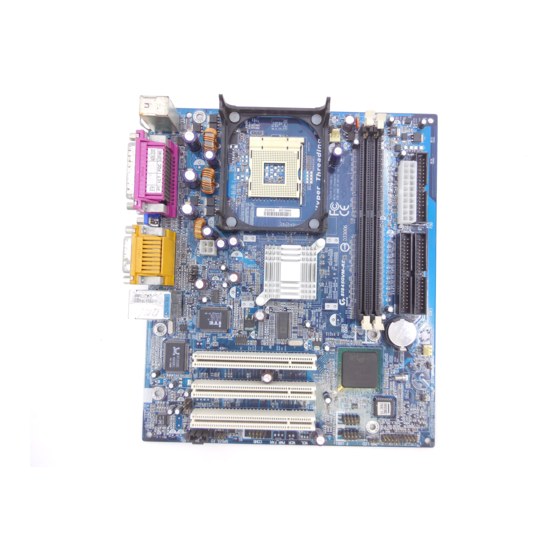
Page 6: 8I845Gvm-Rz Series Motherboard Layout
8I845GVM-RZ Series Motherboard Layout KB_MS ATX_12V F_AUDIO ITE8712 RTL* 8100C SUR_CEN CODEC CD_IN SPDIF_IO "*" For 8I845GVM-RZ only. " " For 8I845GVM-RZ-C only. 8I845GVM-RZ Series Motherboard 20.9 cm CPU_FAN SOCKET 478 Intel 845GV PCI1 Intel ICH4 PCI2 PCI3 F_USB2 COMB... -
Page 7: Block Diagram
RTL8100C* RJ45* AC97 PCICLK CODEC (33MHz) PCICLK (33MHz) USBCLK (48MHz) 14.318 MHz 33 MHz 24 MHz "*" For 8I845GVM-RZ only. CPUCLK+/- (100/133MHz) Pentium 4 System Bus 400/533MHz 333/266 MHz Intel MCHCLK+/- (100/133MHz) 845GV GMCHCLK (66MHz) 66 MHz 33 MHz 14.318 MHz... -
Page 8: Hardware Installation Process
Chipset that supports HT Technology ® - BIOS: A BIOS that supports HT Technology and has it enabled - OS: An operation system that has optimizations for HT Technology 8I845GVM-RZ Series Motherboard Step 1 Step 2 Step 4 - 8 -... -
Page 9: Step 1-1: Cpu Installation
Step 1-1: CPU Installation Figure 1. Socket Pull the rod to the 90-degree directly. Actuation Lever Figure 2. Locate Pin 1 in the socket and look for a (golden) cut edge on the CPU upper corner. Insert the CPU into the socket. (Do not force the CPU into the socket.) Then move the socket lever to the locked position while holding pressure on the center of the CPU. -
Page 10: Step 2: Install Memory Modules
To install the memory module, just push it vertically into the DIMM socket. The DIMM module can only fit in one direction due to the notch. Memory size can vary between sockets. 8I845GVM-RZ Series Motherboard Notch 1. The DIMM socket has a notch, so the DIMM memory module can only fit in one direction. -
Page 11: Step 3: Install Expansion Card
You can connect "Front speaker" to "Line Out" jack, Connect "Rear speaker" to "Line In" jack and connect "Center/Subwoofer" to "MIC In" jack. LAN port* LAN is fast Ethernet with 10/100Mbps speed. "*" For 8I845GVM-RZ only. - 11 - Hardware Installation Process... -
Page 12: Step 4-2: Connectors Introduction
2) ATX 3) CPU_FAN 4) SYS_FAN 5) FDD 6) IDE1 / IDE2 7) F_PANEL 8) PWR_LED 9) DIMM_LED 10) F_AUDIO 8I845GVM-RZ Series Motherboard 11) CD_IN 12) SUR_CEN 13) SPDIF_IO 14) F_USB1 / F_USB2 15) COMB 16) IR 17) CI 18) CLR_CMOS... - Page 13 1) ATX_12V (+12V Power Connector) This connector (ATX_12V) supplies the CPU operation voltage (Vcore). If this "ATX_12V connector" is not connected, system cannot boot. 2) ATX (ATX Power) AC power cord should only be connected to your power supply unit after ATX power cable and other related devices are firmly connected to the mainboard.
- Page 14 6) IDE1 / IDE2 (IDE1 / IDE2 Connector) Please connect first hard disk to IDE1 and connect CD-ROM to IDE2. The red stripe of the ribbon cable must be the same side with the Pin1. 8I845GVM-RZ Series Motherboard Pin No. Definition...
- Page 15 7) F_PANEL (2 x 10 pins Connector) Please connect the power LED, PC speaker, reset switch and power switch etc. of your chassisfront panel to the F_PANEL connector according to the pin assignment below. HD (IDE Hard Disk Active LED) SPK (Speaker Connector) RES (Reset Switch) PW (Soft Power Connector)
- Page 16 Please note, you can have the alternative of using front audio connector or of using rear audio connector to play sound. 11) CD_IN (CD In Connector) Connect CD-ROM or DVD-ROM audio out to the connector. 8I845GVM-RZ Series Motherboard Pin No. Definition Power...
- Page 17 12) SUR_CEN (Surround Center Connector) Please contact your nearest dealer for optional SUR_CEN cable. 13) SPDIF_IO (SPDIF In/Out Connector) The SPDIF output is capable of providing digital audio to external speakers or compressed AC3 data to an external Dolby Digital Decoder. Use this feature only when your stereo system has digital input function.
- Page 18 For optional IR cable, please contact your local dealer. 17) CI (CASE OPEN) This 2-pin connector allows your system to enable or disable the "Case Open" item in BIOS, if the system case begin remove. 8I845GVM-RZ Series Motherboard Pin No. Definition NDCDB-...
- Page 19 18) CLR_CMOS (Clear CMOS) You may clear the CMOS data to its default values by this jumper. To clear CMOS, temporarily shor 1-2 pin. Default doesn't include the "Shunter" to prevent from improper use this jumper. 19) BAT (BATTERY) 1-2 close: Clear CMOS Open: Normal CAUTION Danger of explosion if battery is incorrectly...
- Page 20 8I845GVM-RZ Series Motherboard - 20 -...
-
Page 21: Chapter 2 Bios Setup
Chapter 2 BIOS Setup BIOS Setup is an overview of the BIOS Setup Program. The program that allows users to modify the basic system configuration. This type of information is stored in battery-backed CMOS RAM so that it retains the Setup information when the power is turned off. ENTERING SETUP Powering ON the computer and pressing <Del>... - Page 22 Change, set, or disable password. It allows you to limit access to the system. • Save & Exit Setup Save CMOS value settings to CMOS and exit setup. • Exit Without Saving Abandon all CMOS value changes and exit setup. 8I845GVM-RZ Series Motherboard - 22 -...
-
Page 23: Standard Cmos Features
Standard CMOS Features CMOS Setup Utility-Copyright (C) 1984-2004 Award Software Date (mm:dd:yy) Time (hh:mm:ss) IDE Primary Master IDE Primary Slave IDE Secondary Master IDE Secondary Slave Drive A Drive B Floppy 3 Mode Suport Holt On Base Memory Extended Memory Total Memory : Move Enter: Select... - Page 24 640K for systems with 640K or more memory installed on the motherboard. Extended Memory The BIOS determines how much extended memory is present during the POST. This is the amount of memory located above 1 MB in the CPU's memory address map. 8I845GVM-RZ Series Motherboard - 24 -...
-
Page 25: Advanced Bios Features
Advanced BIOS Features CMOS Setup Utility-Copyright (C) 1984-2004 Award Software First Boot Device Second Boot Device Third Boot Device Boot Up Floppy Seek Password Check CPU Hyper-Threading Init Display First Graphics Aperture Size Graphics Share Memory : Move Enter: Select F5: Previous Values "... -
Page 26: Integrated Peripherals
Auto Will be automatically detected by BIOS. (Default value) ATA66/100 Set IDE1 Conductor Cable to ATA66/100 (Please make sure your IDE device and cable is compatible with ATA66/100). "*" For 8I845GVM-RZ only. 8I845GVM-RZ Series Motherboard Integrated Peripherals [Enabled] [Enabled] [Auto]... - Page 27 This item allows you to determine which Infra Red(IR) function of Onboard I/O chip. Normal Set onboard I/O chip UART to Normal Mode. (Default value) IrDA Set onboard I/O chip UART to IrDA Mode. ASKIR Set onboard I/O chip UART to ASKIR Mode. "*" For 8I845GVM-RZ only. - 27 - BIOS Setup...
- Page 28 Set Midi Port Address to 300. Set Midi Port Address to 330. (Default value) Disabled Disable this function. Midi Port IRQ Set Midi Port IRQ to 5. Set Midi Port IRQ to 10. (Default value) 8I845GVM-RZ Series Motherboard - 28 -...
-
Page 29: Power Management Setup
Power Management Setup CMOS Setup Utility-Copyright (C) 1984-2004 Award Software ACPI Suspend Type Soft-Off by PWR-BTTN PME Event Wake Up ModemRingOn Resume by Alarm x Date (of Month) Alarm x Time (hh:mm:ss) Alarm Power On by Mouse Power On by Keyboard x KB Power ON Password AC Back Function : Move... -
Page 30: Pnp/Pci Configurations
F5: Previous Values PCI 1 IRQ Assignment Auto 3,4,5,7,9,10,11,12,14,15 PCI 2 IRQ Assignment Auto 3,4,5,7,9,10,11,12,14,15 PCI 3 IRQ Assignment Auto 3,4,5,7,9,10,11,12,14,15 8I845GVM-RZ Series Motherboard PnP/PCI Configurations [Auto] [Auto] [Auto] +/-/PU/PD: Value F10: Save ESC: Exit F6: Fail-Save Default F7: Optimized Defaults Auto assign IRQ to PCI 1. -
Page 31: Pc Health Status
PC Health Status CMOS Setup Utility-Copyright (C) 1984-2004 Award Software Reset Case Open Status Case Opened Vcore DDR25V +3.3V +12V Current CPU Temperature Current CPU FAN Speed Current SYSTEM FAN Speed CPU Warning Temperature CPU FAN Fail Warning SYSTEM FAN Fail Warning : Move Enter: Select F5: Previous Values... -
Page 32: Frequency/Voltage Control
PCI/AGP Divider This feature will be available when "CPU Host Clock Control" is set to Enabled. Disabled Disable PCI/AGP Divider control. (Default value) PLL/16, 20, 24, 32, 40 Set PCI/AGP frequency. 8I845GVM-RZ Series Motherboard Frequency/Voltage Control [15X] [Disabled] Disabled [Auto]... -
Page 33: Top Performance
Host/DRAM Clock Ratio Wrong frequency may make system can't boot, clear CMOS to overcome wrong frequency issue. Memory Frequency = Host clock X 2.0. 2.66 Memory Frequency = Host clock X 2.66. Auto Set Memory frequency by DRAM SPD data. (Default value) Memory Frequency (Mhz) The values depend on CPU Host Frequency(Mhz). -
Page 34: Load Optimized Defaults
Frequency/Voltage Control ESC: Quit F8: Q-Flash Selecting this field loads the factory defaults for BIOS and Chipset Features which the system automatically detects. 8I845GVM-RZ Series Motherboard Top Performance Load Fail-Safe Defaults Load Optimized Defaults Set Supervisor Password Set User Password Save &... -
Page 35: Save & Exit Setup
Set Supervisor/User Password CMOS Setup Utility-Copyright (C) 1984-2004 Award Software Standard CMOS Features Advanced BIOS Features Integrated Peripherals Power Management Setup PnP/PCI Configurations Enter Password: PC Health Status Frequency/Voltage Control ESC: Quit F8: Q-Flash When you select this function, the following message will appear at the center of the screen to assist you in creating a password. -
Page 36: Exit Without Saving
Frequency/Voltage Control ESC: Quit F8: Q-Flash Type "Y" will quit the Setup Utility without saving to RTC CMOS. Type "N" will return to Setup Utility. 8I845GVM-RZ Series Motherboard Top Performance Load Fail-Safe Defaults Load Optimized Defaults Set Supervisor Password Save to CMOS and EXIT (Y/N)? Y Set User Password Save &... -
Page 37: Chapter 3 Driver Installation
Revision History Chapter 3 Install Drivers Install Drivers Pictures below are shown in Windows XP Insert the driver CD-title that came with your motherboard into your CD-ROM drive, the driver CD-title will auto start and show the installation guide. If not, please double click the CD-ROM device icon in "My computer", and execute the setup.exe. - Page 38 Pack. After install Windows Service Pack, it will show a question mark "?" in "Universal Serial Bus controller" under "Device Manager". Please remove the question mark and restart the system (System will auto-detect the right USB2.0 driver). "*" For 8I845GVM-RZ only. 8I845GVM-RZ Series Motherboard Driver install finished !
- Page 39 - 39 - Driver Installation...
- Page 40 8I845GVM-RZ Series Motherboard The Netherlands Giga-Byte Technology B.V. Address: Verdunplein 8 5627 SZ, Eindhoven, The Netherlands Tel: +31 40 290 2088 NL Tech.Support : 0900-GIGABYTE (0900-44422983, BE Tech.Support : 0900-84034 ( 0.4/M) Fax: +31 40 290 2089 Tech. Support: http://nz.giga-byte.com/TechSupport/ServiceCenter.htm Non-Tech.