
Related Manuals for Gigabyte 8I945PE-FS


Summary of Contents for Gigabyte 8I945PE-FS
- Page 1 8I945PE-FS Intel Pentium 4 LGA775 Processor Motherboard ® ® User's Manual Rev. 1001...
-
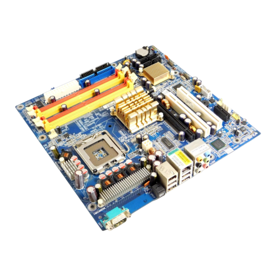
Page 2: Layout
8I945PE-FS Motherboard Layout CPU_FAN LGA775 ATX_12V Intel 945P AUDIO PCIE_16 PCI1 82562 BIOS PCI2 ICH7 TSB43AB23 CODEC PCIE_1 F_1394 CLR_CMOS F_USB1 F-AUDIO F_PANEL SYS_FAN F_USB2 AUX_IN - 2 -... -
Page 3: Block Diagram
Block Diagram CPUCLK+/-(200/133MHz) LGA775 Processor PCI-ECLK(100MHz) Host DDRII 667/533/400MHz DIMM Interface PCI Express x16 Intel Dual Channel Memory 945P MCHCLK (133/200MHz) 66MHz 33MHz 14.318MHz 1 PCI Express x 1 Port 48MHz PCI-ECLK(100MHz) BIOS PCI Express x1 Bus 4 Serial ATA ATA33/66/100 PCI Bus Intel ICH7... -
Page 4: Feature Summary
For example, 4 GB of memory size will instead be shown as 3.xxGB memory during system startup. (Note 2) To use a DDRII 667 memory module on the motherboard, you must install an 800/1066MHz FSB processor . 8I945PE-FS Motherboard - 4 -... - Page 5 I/O Control IT8712 Hardware Monitor System voltage detection CPU temperature detection CPU / System fan speed detection CPU warning temperature CPU / System fan failure warning CPU smart fan control BIOS Use of licensed AWARD BIOS Form Factor Micro ATX form factor; 24.4 cm x 24.4cm - 5 - Hardware Installation...
-
Page 6: Installation Of The Cpu And Heatsink
CPU into position. (Grasping the CPU firmly between your thumb and forefinger, carefully place it into the socket in a straight and downwards motion. Avoid twisting or bending motions that might cause damage to the CPU dur- ing installation.) 8I945PE-FS Motherboard - 6 -... -
Page 7: Installation Of The Heatsink
1-2-2 Installation of the Heatsink Male Push Pin The top of Female Push Pin Female Push Pin Fig.1 Fig. 2 Please apply an even layer of heatsink paste on (Turning the push pin along the direction of arrow the surface of the installed CPU. is to remove the heatsink, on the contrary, is to install.) Please note the direction of arrow sign on the male... -
Page 8: Installation Of Memory
DIMM socket. Then push it down. Fig.2 Close the plastic clip at both edges of the DIMM sockets to lock the DIMM module. Reverse the installation steps when you wish to remove the DIMM module. 8I945PE-FS Motherboard - 8 -... -
Page 9: Installation Of Expansion Cards
GA-8I945PE-FS supports the Dual Channel Technology. After operating the Dual Channel Technology, the bandwidth of Memory Bus will add double. GA-8I945PE-FS includes 4 DIMM sockets, and each Channel has two DIMM sockets as following: Channel A : DDR II 1, DDR II 2... - Page 10 Devices like CD-ROM, walkman etc. can be connected to Line In jack. Line Out (Front Speaker Out) Connect the stereo speakers, earphone or front surround speakers to this connector. MIC In Microphone can be connected to MIC In jack. 8I945PE-FS Motherboard - 10 -...
-
Page 11: Connectors Introduction
Connectors Introduction 1) ATX_12V 9) F_AUDIO 2) ATX (Power Connector) 10) AUX_IN 3) CPU_FAN 11) F_USB1 / F_USB2 4) SYS_FAN 12) F_1394 5) FDD 13) BIOS_RE 6) IDE 14) CLR_CMOS 7) SATA0 / SATA1 / SATA2 / SATA3 15) BAT 8) F_PANEL - 11 - Hardware Installation... - Page 12 Definition +12V +12V Pin No. Definition 3.3V 3.3V Power Good 5V SB(stand by +5V) +12V +12V(Only for 24pins ATX) 3.3V(Only for 24pins ATX) 3.3V -12V PS_ON(soft On/Off) +5V(Only for 24pins ATX) GND(Only for 24pins ATX) 8I945PE-FS Motherboard - 12 -...
- Page 13 3/4) CPU_FAN / SYS_FAN (Cooler Fan Power Connector) The cooler fan power connector supplies a +12V power voltage via a 3-pin/4-pin (only for CPU_FAN) power connector and possesses a foolproof connection design. Most coolers are designed with color-coded power connector wires. A red power connector wire indicates a positive connection and requires a +12V power voltage.
- Page 14 7) SATA0/SATA1/SATA2/SATA3 (SATA 3Gb/s Connector) SATA 3Gb/s can provide up to 300MB/s transfer rate. Please refer to the BIOS setting for the Serial ATA and install the proper driver in order to work properly. Pin No. Definition 8I945PE-FS Motherboard - 14 -...
-
Page 15: Front Panel Jumper
8) F_PANEL (Front Panel Jumper) Please connect the power LED, reset switch and power switch etc. of your chassis front panel to the F_PANEL connector according to the pin assignment below. Message LED/ Power Power/ Switch Sleep LED IDE Hard Disk Reset Switch Active LED HD (IDE Hard Disk Active LED) - Page 16 FSENSE1 FAUOIO_JD No Pin No Pin LINE2_L FSENSE2 Line Out (L) 10) AUX_IN (AUX In Connector) Connect other device (such as PCI TV Tuner audio out) to the connector. Pin No. Definition AUX-L AUX -R 8I945PE-FS Motherboard - 16 -...
- Page 17 11) F_ USB1 / F_USB2 (Front USB Connector) Be careful with the polarity of the front USB connector. Check the pin assignment carefully while you connect the front USB cable, incorrect connection between the cable and connector will make the device unable to work or even damage it. For optional front USB cable, please contact your local dealer.
- Page 18 You may clear the CMOS data to its default values by this jumper. To clear CMOS, temporarily short 1-2 pin. Default doesn't include the "Shunter" to prevent from improper use this jumper. 1-2: Clear CMOS 2-3 : Normal 8I945PE-FS Motherboard - 18 -...
-
Page 19: Hardware Installation
15) BAT(Battery) Danger of explosion if battery is incorrectly replaced. Replace only with the same or equivalent type recommended by the manufacturer. Dispose of used batteries according to the manufacturer's instructions. If you want to erase CMOS... 1. Turn OFF the computer and unplug the power cord. 2. - Page 20 8I945PE-FS Motherboard - 20 -...
- Page 21 Chapter 2 BIOS Setup BIOS (Basic Input and Output System) includes a CMOS SETUP utility which allows user to configure required settings or to activate certain system features. The CMOS SETUP saves the configuration in the CMOS SRAM of the motherboard. When the power is turned off, the battery on the motherboard supplies the necessary power to the CMOS SRAM.
- Page 22 Fail-Safe Defaults indicates the value of the system parameters which the system would be in safe configuration. Load Optimized Defaults Optimized Defaults indicates the value of the system parameters which the system would be in best performance configuration. GA-8I945PE-FS Motherboard - 22 -...
- Page 23 Set Supervisor Password Change, set, or disable password. It allows you to limit access to the system and Setup, or just to Setup. Set User Password Change, set, or disable password. It allows you to limit access to the system. Save &...
-
Page 24: Standard Cmos Features
Select this if no SATA IDE devices are used and the system will skip the automatic detection step and allow for faster system start up. Access Mode Use this to set the access mode for the hard drive. The two options are: Large/Auto(default:Auto) GA-8I945PE-FS Motherboard - 24 -... - Page 25 Capacity Capacity of currently installed hard disk. Hard drive information should be labeled on the outside drive casing. Enter the appropriate option based on this information. Cylinder Number of cylinders Head Number of heads Precomp Write precomp Landing Zone Landing zone Sector Number of sectors Drive A...
-
Page 26: Advanced Bios Features
Select your boot device priority by USB-CDROM. USB-HDD Select your boot device priority by USB-HDD. Select your boot device priority by LAN. Disabled Disable this function. (Note) This item will show up when you install a processor which supports this function. GA-8I945PE-FS Motherboard - 26 -... - Page 27 Boot Up Floppy Seek During POST, BIOS will determine if the installed floppy disk drive is 40 or 80 tracks. 360K type is 40 tracks 720K, 1.2M and 1.44M are all 80 tracks. Disabled BIOS will not search for the type of floppy disk drive by track number. Note that there will not be any warning message if the drive installed is 360K.
-
Page 28: Integrated Peripherals
SATA Port 1/3 Set to This value will auto make by the setting "On-Chip SATA Mode" and "PATA IDE Set to". If PATA IDE were set to Ch. 0 Master/Slave, this function will auto set to Ch. 1 Master/Slave. GA-8I945PE-FS Motherboard - 28 -... - Page 29 USB Controller Enabled Enable USB Controller. (Default value) Disabled Disable USB Controller. USB 2.0 Controller Disable this function if you are not using onboard USB 2.0 feature. Enabled Enable USB 2.0 Controller. (Default value) Disabled Disable USB 2.0 Controller. USB Keyboard Support Enabled Enable USB Keyboard Support.
- Page 30 When AC-power back to the system, the system will be in "Off" state. Full-On When AC-power back to the system, the system always in "On" state. Memory When AC-power back to the system, the system will return to the Last state before AC-power off. (Default value) GA-8I945PE-FS Motherboard - 30 -...
-
Page 31: Power Management Setup
Power Management Setup CMOS Setup Utility-Copyright (C) 1984-2005 Award Software Power Management Setup ACPI Suspend Type [S3(STR)] Item Help USB Device Wake-Up From S3 [Enabled] Menu Level Soft-Off by PWR-BTTN [Instant-Off] PME Event Wake Up [Enabled] Power On by Ring [Enabled] Resume by Alarm [Disabled]... - Page 32 ISA DEVICE. Auto BIOS automatically use these PnP rescuers. (Default value) IRQ assigned ( 3,4,5,7,9,10,11,12,14,15 ) PCI Device This IRQ assigns for PCI device. (Default value) Reserved Reserved this IRQ for other device. GA-8I945PE-FS Motherboard - 32 -...
-
Page 33: Pc Health Status
PC Health Status CMOS Setup Utility-Copyright (C) 1984-2005 Award Software PC Health Status Vcore 1.312V Item Help VCC18 1.792V Menu Level +3.3V 3.232V +12V 11.287V Current CPU Temperature Current CPU FAN Speed 3515 RPM Current SYSTEM FAN Speed CPU Warning Temperature [Disabled] CPU FAN Fail Warning [Disabled]... -
Page 34: Frequency Control
Memory Frequency = Host clock X 2.0. Memory Frequency = Host clock X 2.5. Auto Set Memory frequency by DRAM SPD data. (Default value) Memory Frequency (Mhz) The values depend on "System Memory Multiplier" item. GA-8I945PE-FS Motherboard - 34 -... -
Page 35: Load Optimized Defaults
Load Fail-Safe Defaults CMOS Setup Utility-Copyright (C) 1984-2005 Award Software Standard CMOS Features Load Fail-Safe Defaults Advanced BIOS Features Load Optimized Defaults Integrated Peripherals Set Supervisor Password Power Management Setup Set User Password Load Fail-Safe Defaults (Y/N)? N PnP/PCI Configurations Save &... -
Page 36: Set Supervisor/User Password
Setup Menu. If you select "Setup" at "Password Check" in Advance BIOS Features Menu, you will be prompted only when you try to enter Setup. GA-8I945PE-FS Motherboard - 36 -... -
Page 37: Exit Without Saving
2-11 Save & Exit Setup CMOS Setup Utility-Copyright (C) 1984-2005 Award Software Standard CMOS Features Load Fail-Safe Defaults Advanced BIOS Features Load Optimized Defaults Integrated Peripherals Set Supervisor Password Power Management Setup Set User Password PnP/PCI Configurations Save & Exit Setup Save to CMOS and EXIT (Y/N)? Y PC Health Status Exit Without Saving...