Table of Contents
Advertisement
Available languages
Available languages
Safe Operation Practices • Set-Up • Operation • Maintenance • Service • Troubleshooting • Warranty
O
'
M
peratOr
s
anual
Self Propelled Mower — Models TB210 & TB270 ES
WARNING
READ AND FOLLOW ALL SAFETY RULES AND INSTRUCTIONS IN THIS MANUAL
BEFORE ATTEMPTING TO OPERATE THIS MACHINE.
FAILURE TO COMPLY WITH THESE INSTRUCTIONS MAY RESULT IN PERSONAL INJURY.
TROY-BILT LLC, P.O. BOX 361131 CLEVELAND, OHIO 44136-0019
Printed In USA
Form No. 769-05334
(February 17, 2010)
Advertisement
Chapters
Table of Contents

Related Manuals for Troy-Bilt TB270 ES


Summary of Contents for Troy-Bilt TB270 ES
- Page 1 Safe Operation Practices • Set-Up • Operation • Maintenance • Service • Troubleshooting • Warranty ’ peratOr anual Self Propelled Mower — Models TB210 & TB270 ES WARNING READ AND FOLLOW ALL SAFETY RULES AND INSTRUCTIONS IN THIS MANUAL BEFORE ATTEMPTING TO OPERATE THIS MACHINE.
-
Page 2: Table Of Contents
Choose from the options below: ◊ Visit us on the web at www.troybilt.com ◊ Call a Customer Support Representative at (800) 828-5500 or (330) 558-7220 ◊ Write us at Troy-Bilt LLC • P.O. Box 361131 • Cleveland, OH • 44136-0019... -
Page 3: Safe Operation Practices
Important Safe Operation Practices WARNING: This symbol points out important safety instructions which, if not followed, could endanger the personal safety and/or property of yourself and others. Read and follow all instructions in this manual before attempting to operate this machine. Failure to comply with these instructions may result in personal injury. - Page 4 A missing or damaged discharge cover can cause blade When starting engine, pull cord slowly until resistance contact or thrown object injuries. is felt, then pull rapidly. Rapid retraction of starter cord (kickback) will pull hand and arm toward engine faster than Many injuries occur as a result of the mower being pulled you can let go.
- Page 5 Service Check the blade and engine mounting bolts at frequent intervals for proper tightness. Also, visually inspect blade Safe Handling Of Gasoline: for damage (e.g., bent, cracked, worn) Replace blade with the original equipment manufacture’s (O.E.M.) blade only, To avoid personal injury or property damage use extreme listed in this manual.
- Page 6 Notice Regarding Emissions Spark Arrestor Engines which are certified to comply with California and federal WARNING: This machine is equipped with an EPA emission regulations for SORE (Small Off Road Equipment) internal combustion engine and should not be used are certified to operate on regular unleaded gasoline, and on or near any unimproved forest-covered, brush may include the following emission control systems: Engine covered or grass-covered land unless the engine’s...
- Page 7 Safety Symbols This page depicts and describes safety symbols that may appear on this product. Read, understand, and follow all instructions on the machine before attempting to assemble and operate. Symbol Description READ THE OPERATOR’S MANUAL(S) Read, understand, and follow all instructions in the manual(s) before attempting to assemble and operate DANGER —...
- Page 8 2 — i ectiOn MpOrtant peratiOn ractices...
-
Page 9: Assembly & Set-Up
Assembly & Set-Up Contents of Carton • One Lawn Mower • One Grass Catcher • One Bottle of Oil • One Lawn Mower Operator’s Manual • One Engine Operator’s Manual • One Side Discharge Chute Assembly While stabilizing mower so it doesn’t move, pivot upper handle up as shown in Fig. - Page 10 Remove the T-bolts from the handle brackets as shown in Fig. 3-3. Figure 3-5 The rope guide is attached to the right side of the upper handle. Loosen the wing knob which secures the rope Figure 3-3 guide. See Fig. 3-6. Hold blade control against upper handle.
- Page 11 Side Discharge Chute Slip plastic channel of grass bag over hooks on the frame. See Fig. 3-7. Your mower is shipped as a mulcher. To convert to side discharge, make sure grass catcher is off of the unit and rear discharge door is closed.
- Page 12 Adjustments Handle Pitch For convenience of operation, you may adjust the pitch of the Cutting Height handle as follows: There is a cutting height adjustment lever located above the Remove wing nuts and carriage bolts from handle. See Fig. front and rear right wheel. 3-11.
-
Page 13: Controls & Features
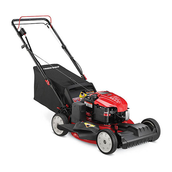
Controls and Features Blade Control Drive Control Electric start Ignition Switch Recoil Starter Side Discharge Chute Deck Wash Cutting Height Adjustment Lever Cutting Height Adjustment Lever Figure 4-1 Blade Control Deck Wash The blade control is attached to the upper handle of the mower. Your mower’s deck is equipped with a water port on its surface Depress and squeeze it against the upper handle to operate the as part of its deck wash system. -
Page 14: Operation
Operation Starting Engine WARNING: Be sure no one other than the operator is standing near the lawn mower while starting engine or operating mower. Never run engine indoors or in enclosed, poorly ventilated areas. Engine exhaust contains carbon monoxide, an odorless and deadly gas. -
Page 15: Maintenance & Adjustment
Maintenance & Adjustments Maintenance The transmission is pre-lubricated and sealed at the factory and does not require lubrication. General Recommendations Follow the accompanying engine manual for lubrication schedule and instruction for engine lubrication. • Always observe safety rules when performing any maintenance. - Page 16 Deck Wash (If Equipped) Engine Care Your mower’s deck may be equipped with a water port on its A list of key engine maintenance jobs required for good surface as part of its deck wash system. performance by the mower is given below. Follow the accompanying engine manual for a detailed list and instructions.
-
Page 17: Service
Service Blade Care Remove blade from the adapter for testing balance. Balance the blade on a round shaft screwdriver to check. WARNING: Remove metal from the heavy side until it balances evenly. When removing the cutting blade for sharpening or replacement, protect your hands with When sharpening the blade, follow the original angle of grind. - Page 18 Replacing Battery (If Equipped) Charging Battery (If Equipped) WARNING: WARNING: Batteries contain sulfuric acid which The battery contains corrosive fluid may cause burns. Do not short circuit or mutilate and toxic material; handle with care and keep away batteries in any way. Do not put batteries in fire as from children.
- Page 19 Replacing Fuse (If Equipped) Off-Season Storage The electric starter circuit and battery are protected by a 40 The following steps should be taken to prepare your lawn mower ampere fuse. If the fuse burns out, the electric starter will not for storage.
-
Page 20: Troubleshooting
Troubleshooting Problem Cause Remedy Engine Fails to start Blade control disengaged. Engage blade control. Spark plug boot disconnected. Connect wire to spark boot. Fuel tank empty or stale fuel. Fill tank with clean, fresh gasoline. Engine not primed (if equipped with primer). Prime engine as instructed in the Operation section. - Page 21 Problem Cause Remedy Uneven cut Wheels not positioned correctly. Place front and rear wheels in same height position. Dull blade. Sharpen or replace blade. Mower will not self propel Belt not installed properly. Check belt for proper pulley installation and movement.
-
Page 22: Replacement Parts
Replacement Parts Component Part Number and Description 759-3338 Spark Plug BS-298090S Fuel Filter † BS-491588S Air Filter Cartridge BS-493537S † Pre-Cleaner BS-793606 Fuel Tank Cap (Briggs & Stratton Model 126T02-0675-B2) BS-794793 Fuel Tank Cap (Briggs & Stratton Model 126L02-4675-F2, 122L05-0768-F1) 734-04018A Wheel (Front) 734-04014B... - Page 23 Component Part Number and Description 964-04117 Grass Bag 954-04259 Belt 725-04329 Battery Charger † 725-04903 Battery † 925-1745A † † If Equipped (800) 828-5500 or (330) 558-7220 Phone to order replacement parts or a complete Parts Manual (have your full model number and serial number ready).
-
Page 24: Warranty
MANUFACTURER’S LIMITED WARRANTY FOR The limited warranty set forth below is given by Troy-Bilt LLC with c. Routine maintenance items such as lubricants, filters, blade respect to new merchandise purchased and used in the United States sharpening, tune-ups, brake adjustments, clutch adjustments,... -
Page 25: Spanish
LEA Y SIGA TODAS LAS INSTRUCCIONES DE ESTE MANUAL ANTES DE PONER EN FUNCIONAMIENTO ESTA MÁQUINA. SI NO RESPETA ESTAS INSTRUCCIONES PUEDE PROVOCAR LESIONES PERSONALES. TROY-BILT LLC, P.O. BOX 361131 CLEVELAND, OHIO 44136-0019 Impreso en Estados Unidos de América Formulario No. 769-05334... - Page 26 Elija entre las opciones que se presentan a continuación: ◊ Visite nuestro sitio web en www.troybilt.com ◊ Llame a un representante de Asistencia al Cliente al (800) 828-5500 ó (330) 558-7220 ◊ Escríbanos a Troy-Bilt LLC • P.O. Box 361131 • Cleveland, OH • 44136-0019...
-
Page 27: Importante Medidas Importantes De Seguridad
Medidas importantes de seguridad ADVERTENCIA: La presencia de este símbolo indica que se trata de instrucciones importantes de seguridad que se deben respetar para evitar poner en peligro su seguridad personal y/o material y la de otras personas. Lea y siga todas las instrucciones de este manual antes de poner en funcionamiento esta máquina. - Page 28 No ponga las manos o los pies cerca de las piezas rotatorias Nunca opere la cortadora sin las guardas apropiadas, o en la tolva de la cortadora. El contacto con las cuchillas cubierta de descarga, guarda para recorte, manija de puede producir la amputación de manos y pies.
- Page 29 Niños Nunca saque la tapa del gas ni agregue combustible mientras el motor está caliente o en marcha. Deje que el Pueden ocurrir accidentes trágicos si el operador no está atento motor se enfríe por lo menos dos minutos antes de volver a a la presencia de niños.
- Page 30 No modifique el motor Nunca trate de ajustar una rueda o la altura de corte mientras el motor está en marcha. Para evitar lesiones graves o la muerte, no modifique el motor Los componentes de la tolva para recorte, cubierta bajo ninguna circunstancia.
- Page 31 Símbolos De Seguridad Esta página representa y describe la seguridad los símbolos que pueden parecer en este producto. Lea, comprenda, y siga todas instrucciones de la máquina antes de intentar ensamblar y operar. Símbolo Descripción LEA EL MANUAL(S) DEL OPERADOR Lea, comprenda, y siga todas instrucciones en el manual (manuales) antes de operar el producto.
- Page 32 2 — M ección edidas iMpOrtantes de seguridad...
-
Page 33: Ensamblado Y Configuración
Montaje y Configuración Contenido de la caja • Una Podadora • Uno Colector de Césped • Uno Botella del Aceite • Uno Manual de Operador • Uno Manual de Operador de Motor • Uno Canal de Descarga Lateral Montaje Si bien la estabilización de cortacésped por lo que no se mueve, pivote asa superior como se muestra NOTA: Esta unidad se envía sin gasolina ni aceite en el motor. - Page 34 Retire la T-pernos de la manija entre corchetes como se Vuelva a colocar tuercas y pernos de transporte muestra en la fig. 3-3. retirarse antes en una reducción de los agujeros de la manija como se muestra en la figura. 3-5. Figura 3-3 Figura 3-5 Siga los siguientes pasos para completar conjunto del...
- Page 35 Colector de Césped Para quitar al receptor de hierba, levante la puerta de descarga trasera en el cortacésped. Receptor de hierba de levantamiento Para ensamblar el colector de césped (de ser necesario), y, lejos de la vara de pivote. El reverso de liberación descarga Haga el cierto bolso es dio vuelta a la derecha el lado antes la puerta para permitir que ello cerrara la apertura trasera del de reunir (la advertencia de la etiqueta será...
- Page 36 Ajustes Inclinación de la manija Por conveniencia de la operación, puede ajustar la inclinación de Altura de Corte la manija de la siguiente manera: Hay una palanca de ajuste de altura de corte, situado encima de Quite los tornillos y tuercas de mariposa transporte de la rueda trasera derecha y la rueda delantera izquierda.
-
Page 37: Controles Y Características
Controles Y Características Control de cuchilla Control de la transmisión Arrancador eléctrico Arrancador de retroceso Canal de Lavado de la Descarga Lateral Plataforma Palanca de ajuste de altura de corte Palanca de ajuste de altura de corte Figura 4-1 Control de Cuchilla Lavado de la Plataforma El control de la cuchilla está... -
Page 38: Funcionamiento
Funcionamiento Encendido del Motor ADVERTENCIA: Asegúrese que ninguna persona aparte del operador permanezca cerca de la podadora mientras arranca el motor u opera la misma. Nunca encienda un motor en espacios cerrados o en una zona con poca ventilación. El escape del motor contiene monóxido de carbono, un gas inodoro y letal. -
Page 39: Mantenimiento Y Ajustes
Mantenimiento Y Ajustes Mantenimiento La transmisión estado prelubricada y sellada en la fábrica y no requiere lubricación. Recomendaciones Generales Siga el manual adjunto del motor para conocer las instrucciones y el programa de lubricación del mismo. • Respete siempre las reglas de seguridad cuando realice tareas de mantenimiento. - Page 40 Lavado de la Plataforma (De ser equipado) Cuidados para el motor La plataforma de su podadora está equipada con un puerto de A continuación se presenta una lista de tareas de mantenimiento agua sobre su superficie como parte del sistema de lavado de la necesarias para el buen funcionamiento de la cortadora de plataforma.
-
Page 41: Servicio
NOTE: Varios componentes deben ser quitados a fin de cambiar Soporte de el cinturón del cortacésped. Ver a un Distribuidor de Servicio de Campana de Troy-Bilt autorizado para hacer sustituir su cinturón. la Cuchilla Perno Figura 7-1 Saque la cuchilla y el adaptador del cigüeñal, Fig. 7-1. - Page 42 Reemplazo de la batería Carga de la batería (De ser equipado) (De ser equipado) ADVERTENCIA: ADVERTENCIA: Las baterías contienen ácido La batería contiene fluido sulfúrico que puede causar quemaduras. No ponga corrosivo y material tóxico; manipule con cuidado y en corto circuito o mutile las baterías de ninguna mantenga alejado de los niños.
- Page 43 Reemplazo del fusible Almacenamiento Fuera de Temporada (De ser equipado) El circuito del arrancador eléctrico y la batería están protegidos Se deben seguir estos pasos para la preparación de la podadora por un fusible de 40 amperes. Si el fusible se quema, el para su almacenamiento.
-
Page 44: Solución De Problemas
Solución de problemas Problema Causa Remedio El motor no arranca El control de lámina se retiró. Contratar el control de lámina. Alambre de bujía desconectado. Unir el alambre a la bujía. Depósito de combustible combustible vacío Llenar el tanque de la gasolina limpia, fresca. o añejo. - Page 45 Problema Causa Remedio Demasiada vibración Cuchilla floja o desequilibrada. Apriete la cuchilla y el adaptador. Equilibre la cuchilla. Cuchilla abollada. Consulte a un distribuidor autorizado. La podadora no abona Césped húmedo. No corte el césped cuando está mojado, el césped espere hasta que sea más tarde para hacerlo.
-
Page 48: Piezas De Reemplazo
Las disposiciones de esta garantía cubren el recurso de reparación zapatas antideslizantes, ruedas de fricción, placas de raspado, gomas única y exclusiva que surge de la venta. Troy-Bilt no se hará helicoidales y neumáticos. responsable de ninguna pérdida o daño incidental o resultante, incluyendo sin limitación, los gastos incurridos para los servicios...