Table of Contents
Advertisement
Quick Links
5AA
1.
1.1. PREFACE ................................................................................. 1-1
1.2. KEY FEATURES ....................................................................... 1-1
1.3. PERFORMANCE LIST .............................................................. 1-3
1.4. BLOCK DIAGRAM..................................................................... 1-4
1.5. INTRODUCE THE PCI - BUS .................................................... 1-5
1.6. FEATURES ............................................................................... 1-5
1.7. What is AGP ............................................................................. 1-6
2.
2.1. HARDWARE ............................................................................. 2-1
2.2. SOFTWARE.............................................................................. 2-2
2.3. ENVIRONMENT ........................................................................ 2-2
3.
3.1. UNPACKING ............................................................................. 3-1
3.2. MAINBOARD LAYOUT.............................................................. 3-2
3.3. QUICK REFERENCE FOR JUMPERS & CONNECTORS .......... 3-3
3.4. SRAM INSTALLATION DRAM INSTALLATION.......................... 3-5
3.5. DRAM INSTALLATION.............................................................. 3-5
3.6. CPU INSTALLATION AND JUMPERS SETUP........................... 3-5
3.7. CMOS RTC & ISA CFG CMOS SRAM....................................... 3-7
3.8. SPEAKER CONNECTOR INSTALLATION................................. 3-7
3.9. ACPI LED CONNECTOR INSTALLATION ................................. 3-7
3.10. HARDWARE RESET SWITCH CONNECTOR INSTALLATION.3-7
TABLE OF CONTENTS
1
Advertisement
Table of Contents

Related Manuals for Gigabyte GA-5AA


Summary of Contents for Gigabyte GA-5AA
-
Page 1: Table Of Contents
TABLE OF CONTENTS INTRODUCTION 1.1. PREFACE ................. 1-1 1.2. KEY FEATURES ............... 1-1 1.3. PERFORMANCE LIST .............. 1-3 1.4. BLOCK DIAGRAM..............1-4 1.5. INTRODUCE THE PCI - BUS ............ 1-5 1.6. FEATURES ................1-5 1.7. What is AGP ................1-6 SPECIFICATION 2.1. - Page 2 Table Of Contents 3.11. GREEN FUNCTION INSTALLATION ........3-8 3.12. PERIPHERAL DEVICE INSTALLATION........3-8 BIOS CONFIGURATION 4.1. ENTERING SETUP ..............4-1 4.2. CONTROL KEYS ..............4-2 4.3. GETTING HELP ................ 4-3 4.3.1. Main Menu................4-3 4.3.2. Status Page Setup Menu / Option Page Setup Menu ....4-3 4.4.
-
Page 3: Introduction
1. INTRODUCTION 1.1. PREFACE Welcome to use the 5AA motherboard. The motherboard is a Pipeline 512 KB CACHE Pentium ® Processor based PC / AT compatible system with ISA bus and PCI Local Bus, and has been designed to be the fastest PC / AT system. There are some new features allow you to operate the system with the performance you want. - Page 4 Introduction Supports 2-channel Enhanced PCI IDE ports for 4 IDE Devices. Supports 2*COM (16550), 1*LPT (EPP / ECP), 1*1.44MB Floppy port. Supports Green function, Plug & Play function. Licensed AMI BIOS, FLASH RAM for BIOS update. 22cm*21cm, Baby AT Form factor. Supports USB port &...
-
Page 5: Performance List
1.3. PERFORMANCE LIST The following list of performance data is the testing results of some popular benchmark testing programs. These data are just referred by users, and there is no responsibility for different testing data values gotten by users. (The different Hardware & Software configuration will result in different benchmark testing results.) •... -
Page 6: Block Diagram
Introduction 1.4. BLOCK DIAGRAM 100MHz 100MHz PBSRAM Host Address Host Data 100MHz MD Bus 66MHz 33MHz MA Bus DRAM 100MHz 100MHz M1542 DEVICE 66MHz 66MHz Device PCI Bus 14.318Hz Device ICS9148 33MHz AF-75 14.318Hz Device GPIO PS/2 33MHz M1543C Keyboard 48MHz Mouse Device... -
Page 7: Introduce The Pci - Bus
1.5. INTRODUCE THE PCI - BUS Connecting devices to a CPU local bus can dramatically increase the speed of I/O- bound peripherals with only a slight increase in cost over traditional systems. This price / Performance point has created a vast market potential for local bus products. -
Page 8: What Is Agp
Introduction 1.7. What is AGP The Accelerated Graphics Port (AGP) is a new port on the Host-To-PCI bridge device that supports an AGP port. The main purpose of the AGP port is to provide fast access to system memory. The AGP port can be used either as fast PCI port (32-bits at 66MHz vs. 32-bits at 33MHz) or as an AGP port which supports 2x data-rate, a read queue, and side band addressing. -
Page 9: Specification
2. SPECIFICATION 2.1. HARDWARE Pentium ® Processor • − 133 / 166 / 200 MHz ; MMX(166 / 200 / 233) − AMD K6 (166 / 200 / 233 / 266 / 300) K6-2 (266 / 300 / 333 / 350 / 366 / 380 / 400 / 450 / 475 / 500) K6-III (400 / 450 / 475 / 500) −... -
Page 10: Software
Specification • − 2-channel Enhanced IDE port on board.(Using IDE PORTS IRQ14,15) − Supports Mode 3,4 IDE & ATAPI CD – ROM. • − Supports 2 x16550 COM ports. (Using IRQ4, 3) I/O PORTS − Supports 1 x EPP/ECP LPT port. (Using IRQ7 or 5 and DMA3 or 1) −... -
Page 11: Hardware Installation
3. HARDWARE INSTALLATION 3.1. UNPACKING The mainboard package should contain the following: • The 5AA mainboard. • USER’ S MANUAL for mainboard. • Cable set for IDE ¡B Floppy ¡B I/O Port & PS/2 (Optional). • Diskette for Mainboard Utility. The mainboard contains sensitive electric components which can be easily damaged by static electricity, so the mainboard should be left in its original packing until it is installed. -
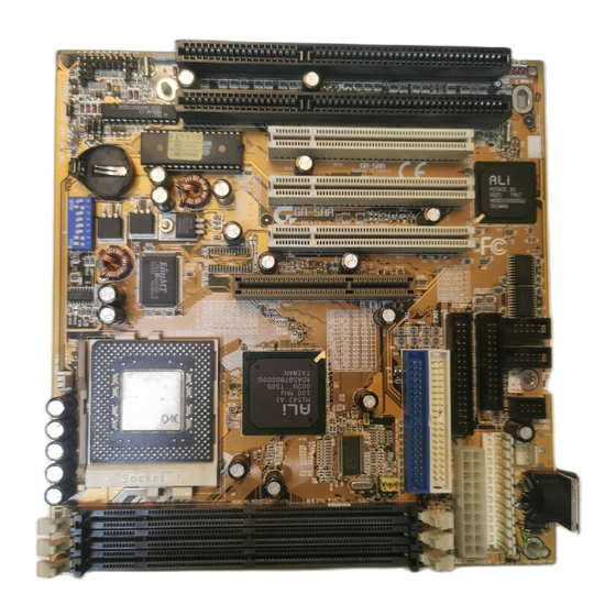
Page 12: Mainboard Layout
Hardware Installation 3.2. MAINBOARD LAYOUT ISA 2 ISA 1 PCI 3 BIOS BAT 1 M1543C PCI 2 PCI 1 COM A COM B JP16 M1542 BANK 2 BANK 1 BANK 0 ×Figure 3.1Ø Optional : ISA 2 ISA 1 PCI 3 BIOS BAT 1 M1543C... -
Page 13: Quick Reference For Jumpers & Connectors
3.3. QUICK REFERENCE FOR JUMPERS & CONNECTORS I/O Port Connectors IDE 1 For Primary IDE port. IDE 2 For Secondary IDE port. FLOPPY For Floppy port. For USB port. COM B For Serial port2 (COM B){Support Modem Ring On}. COM A For Serial port1 (COM A). - Page 14 Hardware Installation TB : Turbo Switch Connector Function Signal RST : RESET Switch Open Normal operation Close Reset system GD : Green LED Connector Function LED anode (+) LED cathode (−) GN : GN-SW Open Normal operation Close Enter Green Mode HD : Hard Disk active LED (HD-LED) Function LED anode (+)
-
Page 15: Dram Installation
FAN Power : CPU cooling FAN Power Connector Function +12V Signal JP7: Keyboard Power On Connector Function 1,2 Close Enabled Keyboard power on. 2,3 Close Disabled Keyboard power on. 3.4. SRAM INSTALLATION Sync. SRAM (Pipeline Burst SRAM) If Sync SRAM Chip is installed, it consists of Pipeline Burst 1 Pc 64 K x 64 512KByte. - Page 16 Hardware Installation 450 / 475 / 500) ; K6-III(400 / 450 / 475 / 500) , Cyrix / IBM 6x86MX (PR166 / PR200 / PR233 / PR266 ) ; M¢ º - PR300 / PR333 / PR366 / PR400 , IDT Winchip II-(200 / 225 / 233 / 266 / 300).
-
Page 17: Cmos Rtc & Isa Cfg Cmos Sram
X5.5 JP14 JP16 100M 105M 110M 115M 120M 125M 130M 135M 140M ♦Note: It’ s strongly recommended that set the system speed according to your hardware configuration: CPU, SDRAM, Cards, etc. ♦Note: If Cyrix 6x86 is being used, please check the CPU Date Code after 605. 3.7. - Page 18 Hardware Installation The RESET switch on panel provides users with HARDWARE RESET function which is almost the same as power-on/off. The system will do a cold start after the RESET switch is pushed and released by user. The RESET switch is a 2 PIN connector and should be installed to RES on mainboard.