Table of Contents
Advertisement
Advertisement
Table of Contents

Related Manuals for Gigabyte GA-586HX


Summary of Contents for Gigabyte GA-586HX
- Page 1 GA - 586HX USER'S MANUAL PCI - ISA SOLUTION PENTIUMä PCI - ISA BUS MAINBOARD REV.2.0 Second Edition Who need 82430HX? 1. If you want to get the best performance. (Because more buffers & Quick DRAM Timing is supported.) 2. If your DATABASE is very imporant.
- Page 2 2. Because user can easily make you memory cacheable size to 512MB. Others can't, because they don't have an EXTRA TAG-RAM socket. 3. Because GA-586HX has 3 banks DRAM, you may upgrade your memory easily & with flexibility. Others don't, because they only have 2 banks 72-pin SIMM modules.
- Page 3 Table of Contents The system tested with 1.2GB hard disk drive, 4 x CD-ROM, and 16MB of EDO RAM. Using each graphics driver provides from Windows95 1024 by 768 resolution with 256 colors, small font, and a refresh rate 72Hz, we defragmented hard disk before each test for Windows95 manage virtual memory setting.
- Page 4 GA-586HX STF 166(P/166) Windows95 256KB Matrox MGA Millennium 80.1 GA-586HX(P/166) Power Desk Windows95 512KB Matrox MGA Millennium 82.4 GA-586HX(P/166) Power Desk Quick Installation Guide: Intel CPU 1. Pentium 75 MHz 2. Pentium 90 MHz 3. Pentium 100 MHz 4. Pentium 120 MHz...
- Page 5 Table of Contents 5. Pentium 133 MHz 6. Pentium 150 MHz/P55C-150MHz 7. Pentium 166 MHz/P55C-166MHz 8. Pentium 180 MHz 9. Pentium 200 MHz/P55C-200MHz 10. P54CT-125 MHz 11. P54CT-150 MHz 12. P54CT-166 MHz...
- Page 6 GA-586HX 13. P54CTB-150 MHz ¬¬ 14. P54CTB-166 MHz ¬¬ 15. P54CTB-180 MHz ¬¬ 16. P54CTB-200 MHz ¬¬...
- Page 7 Table of Contents AMD/Cyrix CPU 17. AMDK5- 75 MHz-P75 18. AMDK5- 90 MHz-P90 19. AMDK5-100 MHz-P100 20. AMDK5- 90 MHz-P120 21. AMDK5-100 MHz-P133 22. AMDK5-P166 23. AMDK5-P200 24. Cyrix 6x86-100 MHz-P120+...
- Page 8 28. Cyrix 6x86L- P150+ 2.8V 29. Cyrix 6x86L-P166+ 2.8V ¬ Note : If Cyrix 6x86 is being used, please check the CPU Date Code after 605. ¬¬ Note : To Support Intel CPU P54CTB-150MHz/166MHz/180MHz/200MHz, GA-586HX Is Available From PCB Ver.1.54.
- Page 9 Table of Contents Pentium 75 MHz µ § Pentium 90 MHz µ § Pentium 100 MHz µ § Pentium 120 MHz µ § Pentium 133 MHz µ § Pentium 150 MHz/P55C-150MHz µ § Pentium 166 MHz/P55C-166MHz µ § Pentium 180 MHz µ...
- Page 10 GA-586HX Pentium 200 MHz/P55C-200MHz µ § 10. P54CT-125 MHz µ § 11. P54CT-150 MHz µ § 12. P54CT-166 MHz µ § 13. P54CTB-150 MHz µ § 14. P54CTB-166 MHz µ § 15. P54CTB-180 MHz µ §...
- Page 11 Table of Contents 16. P54CTB-200 MHz µ § 17. AMDK5- 75 MHz-P75 µ § 18. AMDK5- 90 MHz-P90 µ § 19. AMDK5-100 MHz-P100 µ § 20. AMDK5- 90 MHz-P120 µ § 21. AMDK5-100 MHz-P133 µ § 22. AMDK5-P166...
- Page 12 GA-586HX µ § 23. AMDK5-P200 µ § 24. Cyrix 6x86-100 MHz-P120+ µ § 25. Cyrix 6x86-110 MHz-P133+ µ § 26. Cyrix 6x86-120 MHz-P150+ µ § 27. Cyrix 6x86-133 MHz-P166+ µ § 28. Cyrix 6x86L-P150+ 2.8V µ § 29. Cyrix 6x86L-P166+ 2.8V...
- Page 13 Table of Contents µ §...
- Page 14 GA-586HX III. SRAM Install µ § µ § IV. Quick Installation Guide of Jumper setting: µ § µ § µ § µ § µ § µ § µ § µ § µ § µ § µ § µ § µ...
- Page 15 Table of Contents µ § µ § µ § µ § µ § µ § µ § V. Top Performance Test Setting: Note:Users have to modify the value for each item in chipset features as follow: Note:60ns EDO-60ns DRAM is necessary for top performance setting. Chipset features setup §...
- Page 16 GA-586HX The author assumes no responsibility for any errors or omissions which may appear in this document nor does it make a commitment to update the information contained herein. IBM PC/AT, PC/XT are trademarks of International Business Machine Corporation. PENTIUM is a trademark of Intel Corporation.
-
Page 17: Table Of Contents
Table of Contents TABLE OF CONTENTS µ1. INTRODUCTION....................1-1 1.1. PREFACE......................1-1 1.2. KEY FEATURES.....................1-1 1.3. PERFORMANCE LIST..................1-2 1.4. BLOCK DIAGRAM..................1-4 1.5. INTRODUCE THE PCI - BUS.................1-5 1.6. FEATURES......................1-5 2. SPECIFICATION....................2-1 2.1. HARDWARE....................2-1 2.2. SOFTWARE.....................2-2 2.3. ENVIRONMENT.....................2-2 3. HARDWARE INSTALLATION................3-1 3.1. UNPACKING....................3-1 3.2. - Page 18 GA-586HX 4.3.2. Status Page Setup Menu / Option Page Setup Menu........4-2 4.4. THE MAIN MENU..................4-2 4.5. STANDARD CMOS SETUP MENU...............4-4 4.6. BIOS FEATURES SETUP................4-7 4.7. CHIPSET FEATURES SETUP................4-10 4.8. POWER MANAGEMENT SETUP..............4-14 4.9. PNP/PCI CONFIGURATION................4-16 4.10. LOAD BIOS DEFAULTS................4-17 4.11. LOAD SETUP DEFAULTS................4-18 4.12.
-
Page 19: Preface
GA-586HX INTRODUCTION 1.1. PREFACE Welcome to use the GA - 586HX motherboard. The motherboard is a Pipeline 256 KB / 512 KB CACHE PENTIUMä Processor based PC / AT compatible system with ISA bus and PCI Local Bus, and has been designed to be the fastest PC / AT system. -
Page 20: Performance List
Introduction 1.3. PERFORMANCE LIST The following performance data list is the testing results of some popular benchmark testing programs. These data are just referred by users, and there is no responsibility for different testing data values gotten by users. (The different Hardware & Software configuration will result in different benchmark testing results.) ·... - Page 21 GA-586HX V1.81 Data Transfer Rate KB/S 14481.9 14694.8 Mean Seek 10.2 10.4 Track-Track Seek Norton System Info. Index 423.5 529.4 V8.0 Disk Index Core Test DATA Transfer Rate KB/S 13552 13568 Sequential Read 6304 6320 V.3.02 Random Read 2384 2384...
- Page 22 Introduction Winbench 96 22.6 25.3 Winstone 96 Winstone 96 87.3 · Pentiumä processor 133/166 MHz · EDO 8MB 2pcs. Total 16 MB DRAM (Panasonic EUXSR08XX00E) · 512 KB Pipeline Burst SRAM CACHE SIZE (UMC UM61L3232AF-7) · DIAMOND STEALTH 64 PCI S3-968 DISPLAY ·...
- Page 23 GA-586HX Mean Seek 10.3 10.4 Track-Track Seek Norton System Info. Index 423.5 529.4 V8.0 Disk Index 22.0 Core Test DATA Transfer Rate KB/S 13552 13632 Sequential Read 6304 6320 V.3.02 Random Read 2384 2384 Performance Index Index 86.08 86.42 DOS Mark Index 1090.78...
- Page 24 Introduction Winbench 96 22.9 25.8 Winstone 96 Winstone 96 88.3 96.7...
-
Page 25: Block Diagram
GA-586HX 1.4. BLOCK DIAGRAM § µ... -
Page 26: Introduce The Pci - Bus
Introduction 1.5. INTRODUCE THE PCI - BUS Connecting devices to a CPU local bus can dramatically increase the speed of I/O- bound peripherals with only a slight increase in cost over traditional systems. This price / performance point has created a vast market potential for local bus products. The main barrier to this market has been the lack of an accepted standard for local bus peripherals. -
Page 27: Specification
Specification SPECIFICATION 2.1. HARDWARE · Pentiumä processor 75 - 200 MHz, P55C, P54CT, P54CTB, AMDK5(P-75/P-90/P-100/P-120/P-133/P- 166/P-200), Cyrix6 x 86(P-120+/P-133+/P-150+/P- 166+), Cyrix6x86L(P-150+/P-166+ 2.8V) . 321 pins (socket 7) ZIF white socket on board. 3.52V / 2.8V Dual Power Ready. · Included in Pentium. COPROCESSOR ·... -
Page 28: Software
GA-586HX · Supports 2 16550 COM ports. (Using IRQ4, 3) I/O PORTS Supports 1 EPP/ECP LPT port. (Using IRQ7 or 5 and DMA3 or 1) Supports 1 1.44MB Floppy port. (Using DMA2 & IRQ6) Supports PS/2 Mouse. (Using IRQ12 ) ·... - Page 29 Specification · 0 to 1,000 Hz. Vibration · 4.9 V to 5.2 V. Electricity...
-
Page 30: Hardware Installation
Hardware Installation HARDWARE INSTALLATION 3.1. UNPACKING The mainboard package should contain the following: · The GA - 586HX mainboard. · USER'S MANUAL. · Cable set for I/O Device. · Diskette for BUS Master IDE Driver. The mainboard contains sensitive electric components which can be easily damaged by static electricity, so the mainboard should be left in its original packing until it is installed. -
Page 31: Mainboard Layout
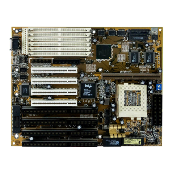
GA-586HX 3.2. MAINBOARD LAYOUT µ §×Figure 3.1Ø 3.3. QUICK REFERENCE FOR JUMPERS & CONNECTORS HD: IDE Hard Disk Active LED Pin No. Function LED anode (+). LED cathode (-). LED cathode (-). LED anode (+). GN: Green Function Switch Pin No. - Page 32 Hardware Installation LED cathode (-). RST: Reset Switch Open For normal operation. Close For hardware reset system. TB: Turbo Switch *Don't switch TB function when system is live. Pin No. Function Close For low speed (50MHz). Open For high speed. TD: Turbo LED Connector Pin No.
- Page 33 GA-586HX Data. PWR: Power LED and Key-Lock Connector Pin No. Function LED anode (+). LED cathode (-). Key lock. GND. POWER: Power Connector Pin No. Function Power Good signal 2,10,11,12 VCC (+5V) +12V...
- Page 34 Hardware Installation -12V 5,6,7,8 J1: Keyboard Connector Pin No. Function Key Clock. Key Data. VCC (+5V). GND. J9: CPU Cooling Fan Power Connector Pin No. Function +12V JP1,2: System Speed Selection (For Motherboard with JP1, JP2)
- Page 35 GA-586HX Function For 50 MHz system speed ( CPU 75, 100(x2) MHz ). For 60 MHz system speed ( CPU 90, 120, 150, 180 MHz ). For 66 MHz system speed ( CPU 100, 133, 166, 200 MHz ). JP3: CPU INT. / EXT. FREQ. RATIO (For Motherboard with JP3)
-
Page 36: Dram Installation
Hardware Installation X 2.5 CN3,4,J2,3,4,5,6 I/O Ports Connector For Primary IDE port For Secondary IDE port For PS/2 Mouse port. For COM A (Serial port1) For COM B (Serial port2) For LPT port For Floppy port 3.4. DRAM INSTALLATION The mainboard can be installed with 4 / 8 / 16 / 32 MB 72 pins SIMM module DRAM, and the DRAM speed must be 60 or 70 ns. - Page 37 GA-586HX completely. After completely insert SIMM module into socket, then press the SIMM module in vertical direction until the left and right metal holders can keep the SIMM module standing up firmly. DRAM configuration table: BANK0 BANK1 BANK2 TOTAL SIZE 4MB * 2pcs.
- Page 38 Hardware Installation 16MB * 2pcs. 8MB * 2pcs. 4MB * 2pcs. 56MB 16MB * 2pcs. 8MB * 2pcs. 8MB * 2pcs. 64MB 16MB * 2pcs. 16MB * 2pcs. 64MB 32MB * 2pcs. 64MB 32MB * 2pcs. 4MB * 2pcs. 72MB 16MB * 2pcs.
- Page 39 GA-586HX 64MB * 2pcs. 128MB 32MB * 2pcs. 32MB * 2pcs. 128MB 32MB * 2pcs. 16MB * 2pcs. 16MB * 2pcs. 128MB 64MB * 2pcs. 4MB * 2pcs. 136MB 32MB * 2pcs. 32MB * 2pcs. 4MB * 2pcs. 136MB 64MB * 2pcs.
- Page 40 Hardware Installation 64MB * 2pcs. 32MB * 2pcs. 192MB 64MB * 2pcs. 32MB * 2pcs. 4MB * 2pcs. 200MB 64MB * 2pcs. 32MB * 2pcs. 8MB * 2pcs. 208MB 64MB * 2pcs. 32MB * 2pcs. 16MB * 2pcs. 224MB 64MB * 2pcs. 32MB * 2pcs.
- Page 41 GA-586HX 128MB * 2pcs. 16MB * 2pcs. 4MB * 2pcs. 296MB 128MB * 2pcs. 16MB * 2pcs. 8MB * 2pcs. 304MB 128MB * 2pcs. 16MB * 2pcs. 16MB * 2pcs. 320MB 128MB * 2pcs. 32MB * 2pcs. 320MB 128MB * 2pcs.
- Page 42 Hardware Installation 3-13...
-
Page 43: Sram Installation
GA-586HX 3.5. SRAM INSTALLATION Sync. SRAM (PipeLine Burst SRAM) If Sync SRAM Module is installed, it consists of Pipeline Burst 2 PCs 32 K x 32 from 256K upgrade to 512K. If your DRAM size > 64MB, suggest you install U4 (TAG RAM 16Kx8-15) for full DRAM Range cacheable. -
Page 44: Speaker Connector Installation
Hardware Installation 3.8. SPEAKER CONNECTOR INSTALLATION There is always a speaker in AT system for sound purpose. The 4 - Pins connector SPK is used to connect speaker. The speaker can work well in both direction of connector when it is installed to the connector SPK on mainboard. 3.9. -
Page 45: Peripheral Device Installation
GA-586HX 3.14. PERIPHERAL DEVICE INSTALLATION After installation of the device and setup of the jumpers, the mainboard can be mounted into the case and fixed by screw. To complete the mainboard installation, the peripheral devices could be installed now. The basic system needs a display interface card and a storage device. -
Page 46: Bios Configuration
GA-586HX BIOS CONFIGURATION Award's BIOS ROM has a built-in Setup program that allows users to modify the basic system configuration. This type of information is stored in battery-backed CMOS SRAM so that it retains the Setup information when the power is turned off. -
Page 47: Getting Help
BIOS Configuration F1 key General help, only for Status Page Setup Menu and Option Page Setup Menu F2 key Change color from total 16 colors F3 key Calendar, only for Status Page Setup Menu F4 key Reserved F5 key Restore the previous CMOS value from CMOS, only for Option Page Setup Menu F6 key Load the default CMOS value from BIOS default table, only for Option... - Page 48 GA-586HX functions and two exit choices. Use arrow keys to select among the items and press <Enter> to accept or enter the sub-menu. § µ Figure 4.1: Main Menu · Standard CMOS setup This setup page includes all the items in a standard compatible BIOS.
-
Page 49: Standard Cmos Setup Menu
BIOS Configuration Low level format IDE Hard Disk. · Save & exit setup Save CMOS value changes to CMOS and exit setup. · Exit without save Abandon all CMOS value changes and exit setup. 4.5. STANDARD CMOS SETUP MENU The items in Standard CMOS Setup Menu (Figure 4.2) are divided into 8 categories. Each category includes no, one or more than one setup items. - Page 50 GA-586HX and type Auto will automatically detect HDD's type.. Press PgUp or PgDn to select a numbered hard disk type or type the number and press <Enter>. Note that the specifications of your drive must match with the drive table. The hard disk will not work properly if you enter improper information for this category.
- Page 51 BIOS Configuration 2.88M, 3.5 in. 3-1/2 inch double-sided drive; 2.88 megabyte capacity. · Floppy 3 Mode Support Disabled No 3 mode floppy drive installed. Drive A Installed 3 mode drive at drive A. Drive B Installed 3 mode drive at drive B. Both Installed 3 mode drive at drive A and drive B.
- Page 52 GA-586HX may be detected All errors Whenever the BIOS detects a non-fatal error the system will be stopped and you will be prompted All,But Keyboard The system boot will not stop for a keyboard error; it will stop for all other errors All, But Diskette The system boot will not stop for a disk error;...
-
Page 53: Bios Features Setup
BIOS Configuration for application programs. Most use for this area is Shadow RAM. 4.6. BIOS FEATURES SETUP § µ Figure 4.3: BIOS Features Setup · Virus Warning This category flashes on the screen. During and after the system boots up, any attempt to write to the boot sector or partition table of the hard disk drive will halt the system and the following error message will appear. - Page 54 GA-586HX This category determines which drive computer searches first for the disk operating system (i.e., DOS). Default value is A,C. System will first search for floppy disk drive then hard disk drive. System will first search for hard disk drive then floppy disk drive.
- Page 55 BIOS Configuration · Boot Up System Speed The default value is High. High CPU input clock depends on the setting of TB (CPU input clock jumper). CPU input clock is fixed on 40 MHz. · Security Option This category allows you to limit access to the system and Setup, or just to Setup.
-
Page 56: Chipset Features Setup
GA-586HX · OS Select For DRAM>64MB The default value is Non-OS2. Non-OS2 Using non-OS2 operating system. Using OS2 operating system and DRAM>64MB. · Video BIOS Shadow It determines whether video BIOS will be copied to RAM, however, it is optional from chipset design. Video Shadow will increase the video speed. The default value is Enable. - Page 57 BIOS Configuration · DRAM Timing The default value is 70 ns. 60 ns Using 60ns DRAM speed. 70 ns Using 70ns DRAM speed. · DRAM RAS# Precharge Time The default value is 4. Set DRAM RAS# precharge time to 3. Set DRAM RAS# precharge time to 4.
- Page 58 GA-586HX x222/x333 Set DRAM read burst to x222/x333. · DRAM write Burst timing The default value is x444. x222 Set DRAM write burst timing to x222. x333 Set DRAM write burst timing to x333. x444 Set DRAM write burst timing to x444.
- Page 59 BIOS Configuration · ISA Clock The default value is PCICLK/4. PCICLK/3 For 50 MHz system. PCICLK/4 For 66,60 MHz system. · System BIOS Cacheable The default value is Enabled. Enabled Enable system BIOS cacheable. Disabled Disable system BIOS cacheable. · Video BIOS Cacheable The default value is Enabled.
- Page 60 GA-586HX The default value is 1. Set 16 Bit I/O recovery time from 1 to 4. None. · Memory Hole At 15M-16M The default value is Disabled. Disabled Normal Setting. Enabled Set Address=15~16MB remap to ISA BUS. · Peer Concurrency The default value is Enabled.
- Page 61 BIOS Configuration Only for type of DRAM which with Extra bit for ECC/ Parity. · Single Bit Error Report The default value is Enabled. Disabled Disable Single Bit Error Report. Enabled Enable Single Bit Error Report. · L2 Cache Cacheable Size The default value is 64MB.
-
Page 62: Power Management Setup
GA-586HX Disabled Disable Passive Release. · Delayed Transaction The default value is Disabled. Enabled Enable Delayed Transaction. Disabled Disabled Delayed Transaction. 4.8. POWER MANAGEMENT SETUP § µ Figure 4.5: Power Management Setup · Power Management The default value is Enabled. - Page 63 BIOS Configuration · Video off Method The default value is DPMS. V/H SYNC+Blank BIOS will turn off V/H-SYNC when gets into Green mode for Green monitor power saving. Blank Screen BIOS will only black monitor when gets into Green mode. DPMS BIOS will use DPMS Standard to control VGA card.
- Page 64 GA-586HX · IRQX ( 3,4,5,6,7,9,10,11,12,14,15 ) The default value is On. The system will return to normal mode from Green Mode when the IRQX is active. The system will not return to normal mode from Green Mode when the IRQX is active.
-
Page 65: Pnp/Pci Configuration
BIOS Configuration 4.9. PNP/PCI CONFIGURATION § µ Figure 4.6: PNP/PCI Configuration · Resources Controlled By The default value is Manual. Manual Disable resources controlled. Auto Enable resources controlled. · Reset Configuration Data The default value is Disabled. Disabled Disable reset configuration data. Enabled Enable reset configuration data. -
Page 66: Load Bios Defaults
GA-586HX PCI-Slot1~PCI-Slot4 Map PCI IDE-IRQ to PCI-Slot1~PCI-Slot4. · Primary/Secondary IDE INT# Set INTA for primary/secondary PCI IDE. Set INTB for primary/secondary PCI IDE. Set INTC for primary/secondary PCI IDE. Set INTD for primary/secondary PCI IDE. 4.10. LOAD BIOS DEFAULTS µ §... -
Page 67: Load Setup Defaults
BIOS Configuration 4.11. LOAD SETUP DEFAULTS µ § Figure 4.8: Load Setup Defaults · Load SETUP Defaults To load SETUP defaults value to CMOS SRAM, enter "Y". If not, enter "N". If there is any problem occurred, loading SETUP DEFAULTS step is recommended. -
Page 68: Integrated Peripherals
GA-586HX 4.12. INTEGRATED PERIPHERALS µ § Figure 4.9: Integrated Peripherals · IDE HDD Block Mode The default value is Enabled. Enabled Enable IDE HDD Block Mode Disabled Disable IDE HDD Block Mode · On-chip Primary/Secondary PCI IDE The default value is Enabled. - Page 69 BIOS Configuration Mode0~4 Manually set the IDE Accessing mode. · IDE Secondary Slave PIO (for onboard IDE 2nd channel). The default value is Auto. Auto BIOS will automatically defect the IDE HDD Accessing mode. Mode0~4 Manually set the IDE Accessing mode. ·...
- Page 70 GA-586HX The default value is 2F8/IRQ3. 3F8/IRQ4 Enable onboard Serial port 2 and address is 3F8H. 2F8/IRQ3 Enable onboard Serial port 2 and address is 2F8H. 3E8/IRQ4 Enable onboard Serial port 2 and address is 3E8H. 2E8/IRQ3 Enable onboard Serial port 2 and address is 2E8H.
-
Page 71: Supervisor / User Password
BIOS Configuration ECP/EPP Using Parallel port as ECP & EPP mode/Enhanced Parallel ¯ Port. As EPP/SPP Mode is selected, two options can be defined: 1. Parallel Port EPP type: EPP1.7 2.Parallel Port EPP type: EPP1.9 ¯ As ECP,ECP/EPP Mode is selected, two options can be defined: 1. - Page 72 GA-586HX Type "N" will keep the old H.D.D. parameter setup. If the hard disk cylinder NO. is over 1024, then the user can select LBA mode or LARGER mode for DOS partition LARGE than 528 MB. 4-27...
-
Page 73: Hdd Low Level Format
BIOS Configuration 4.15. HDD LOW LEVEL FORMAT µ § Figure 4.12: HDD Low Level Format HDD Low Level Format Utility: In main manual: There are three options to choose: one is: SELECT DRIVE: "C" or "D". another one is: BAD TRACK LIST: User can auto, add, modify, delete, clear for bad track of HDD. -
Page 74: Save & Exit Setup
GA-586HX 4.16. SAVE & EXIT SETUP µ § Figure 4.13: Save & Exit Setup Type "Y" will quit the Setup Utility and save the user setup value to RTC CMOS SRAM. Type "N" will return to Setup Utility. 4-29... -
Page 75: Exit Without Saving
BIOS Configuration 4.17. EXIT WITHOUT SAVING µ § Figure 4.15: Exit Without Saving Type "Y" will quit the Setup Utility without saving to RTC CMOS SRAM. Type "N" will return to Setup Utility. 4-30... -
Page 76: At Technical Information
AT Technical Information 5. AT TECHNICAL INFORMATION 5.1. I/O BUS CONNECTOR PIN OUT Enhanced Parallel Port 5.1.1. ISA SLOT PIN OUT § µ... -
Page 77: Pci - Bus Slot Pin Out
GA-586HX 5.1.2. PCI - BUS SLOT PIN OUT § µ... -
Page 78: I/O & Memory Map
AT Technical Information 5.2. I/O & MEMORY MAP MEMORY MAP: [0000000-009FFFF] System memory used by DOS and application program. [00A0000-00BFFFF] Display buffer memory for VGA/ EGA/CGA/MONOCHROME adapter. [00C0000-00DFFFF] Reserved for I/O device BIOS ROM or RAM buffer. [00E0000-00EFFFF] Reserved for PCI device ROM. [00F0000-00FFFFF] System BIOS ROM. -
Page 79: Timer & Dma Channels Map
GA-586HX [378-37F] PARALLEL port-1 [3B0-3BF] MONOCHROME & PRINTER adapter. [3C0-3CF] EGA adapter. [3D0-3DF] CGA adapter. [3F0-3F7] FLOPPY DISK controller. [3F8-3FF] SERIAL port-1. 5.3. TIMER & DMA CHANNELS MAP TIMER MAP: TIMER Channel-0 System timer interrupt TIMER Channel-1 DRAM REFRESH request... - Page 80 AT Technical Information DMA Channel-5 Available DMA Channel-6 Available DMA Channel-7 Available...
-
Page 81: Interrupt Map
GA-586HX 5.4. INTERRUPT MAP NMI: Parity check error IRQ (H/W): 0 System TIMER interrupt from TIMER-0 1 KEYBOARD output buffer full 2 Cascade for IRQ 8-15 3 SERIAL port 2 4 SERIAL port 1 5 PARALLEL port 2 6 FLOPPY DISK adapter... - Page 82 AT Technical Information 8 RTC clock 9 Available 10 Available 11 Available 12 PS/2 Mouse 13 MATH coprocessor 14 HARD DISK adapter 15 Available...
-
Page 83: Rtc & Cmos Ram Map
GA-586HX 5.5. RTC & CMOS RAM MAP RTC & CMOS: Seconds Second alarm Minutes Minutes alarm Hours Hours alarm Day of week Day of month Month Year Status register A Status register B Status register C... - Page 84 AT Technical Information Status register D Diagnostic status byte Shutdown byte FLOPPY DISK drive type byte Reserve HARD DISK type byte Reserve Equipment byte Base memory low byte Base memory high byte Extension memory low byte Extension memory high byte 19-2d 2E-2F...
- Page 85 GA-586HX Reserved for extension memory low byte Reserved for extension memory high byte DATE CENTURY byte INFORMATION FLAG 34-3F Reserve 40-7f Reserved for CHIPSET SETTING DATA 5-10...
-
Page 86: Appendix A: Post Message
GA-586HX APPENDIX A: POST MESSAGE When the BIOS encounters an error that requires the user to correct something, either a beep code will sound or a message will be displayed in a box in the middle of the screen and the message PRESS F1 TO CONTINUE, CTRL-ALT-ESC OR DEL TO ENTER SETUP will be shown in the information box at the bottom. - Page 87 Appendix A: Post Message Ö DISPLAY SWITCH IS SET INCORRECTLY Display switch on the motherboard can be set to either monochrome or color. This indicates the switch is set to a different setting than indicated in Setup. Determine which setting is correct, and then either turn off the system and change the jumper, or enter Setup and change the VIDEO selection.
- Page 88 GA-586HX PLEASE RUN EISA CONFIGURATION UTILITY The non-volatile memory containing EISA configuration information was programmed incorrectly or has become corrupted. Re-run EISA configuration utility to correctly program the memory. When this error appears, the system will boot in ISA mode, which allows you to run the EISA Configuration Utility.
- Page 89 Appendix A: Post Message PARITY ERROR messages when the segment that has caused the problem has been isolated. Ö PRESS A KEY TO REBOOT This will be displayed at the bottom screen when an error occurs that requires you to reboot. Press any key and the system will reboot. Ö...
- Page 90 GA-586HX Ö SYSTEM HALTED, (CTRL-ALT-DEL) TO REBOOT ... Indicates the present boot attempt has been aborted and the system must be rebooted. Press and hold down the CTRL and ALT keys and press DEL. Ö Wrong Board In Slot PLEASE RUN EISA CONFIGURATION UTILITY The board ID does not match the ID stored in the EISA non-volatile memory.
-
Page 91: Appendix B: Post Codes
Appendix B: Post Codes APPENDIX B: POST CODES EISA POST codes are typically output to port address 300h. ISA POST codes are typically output to port address 80h. POST Name Description Turn Off Chipset OEM Specific-Cache control. Cache Processor Test 1 Processor Status (1 FLAGS) Verification. - Page 92 GA-586HX Test CMOS Verifies CMOS is working correctly, detects bad battery. Interface and Battery Status Chipset Default Program chipset registers with power on BIOS defaults. Initialization Memory presence OEM Specific-Test to size on-board memory. test Early Shadow OEM Specific-Early Shadow enable for fast boot.
- Page 93 Appendix B: Post Codes Test Video Memory Test video memory, write sign-on message to screen. Setup shadow RAM - Enable shadow according to Setup. Test DMA BIOS checksum test. Controller 0 Keyboard detect and initialization. Test DMA Controller 1 Test DMA Page Test DMA Page Registers.
- Page 94 GA-586HX EISA mode flag. Test EISA Configuration Memory Integrity (checksum & communication interface). Enable Slot 0 Initialize slot 0 (System Board). 21-2F Enable Slots 1-15 Initialize slot 1 through 15. Size Base and Size base memory from 256 K to 640 K extended Extended Memory memory above 1 MB.
- Page 95 Appendix B: Post Codes Display virus protest disable or enable. Initialize Floppy Initialize floppy disk drive controller and any drives. Drive & Controller Initialize Hard Initialize hard drive controller and any drives. Drive & Controller Detect & Initialize Initialize any serial and parallel ports (also game port). Serial/Parallel Ports Reserved Detect &...
- Page 96 GA-586HX Initialize Option Initialize any option ROMs present from C8000h to ROMs EFFFFh. When FSCAN option is enabled, will initialize from C8000h to F7FFFh. Initialize Time Initialize time value in 40h: BIOS area. Value Setup Virus Protect Setup virus protect according to Setup...
-
Page 97: Appendix C: Bios Default Drive Table
Appendix C: BIOS Default Drive Table APPENDIX C: BIOS DEFAULT DRIVE TABLE Type Size Cylinders Heads Sectors Write / Land Example Model (MB) Precomp Zone 10 MB TEAC SD510 MMI 112, 5412 20 MB Seagate ST225, ST4026 31 MB 62 MB 47 MB 20 MB 65535... - Page 98 GA-586HX 50 MB 65535 20 MB Disctron526, MMI M125 43 MB 65535 20 MB Microscience HH725 Syquest3250, 3425 41 MB 57 MB 65535 60 MB 1024 1023 30 MB 43 MB 30 MB Seagate ST4038 10 MB 54 MB Seagate ST4051...
- Page 99 Appendix C: BIOS Default Drive Table 69 MB 65535 Seagate ST4096 44 MB Maxtor2085 69 MB 65535 Maxtor2140, Priam S14 41 MB Maxtor2190, Priam S19 68 MB 65535 Maxtor1085 Micropolis1325 53 MB Maxtor1105, 1120, 4780 94 MB 1024 65535 1024 Maxtor1170 128 MB 1024...
- Page 100 GA-586HX 25 MB 57 MB Maxtor1140, 4380 41 MB Seagate ST251 41 MB Seagate ST4053 Miniscribe3053/ 6053 41 MB Miniscribe3053/ 6053 RLL 48 MB Miniscribe 3650 69 MB 65535 Miniscribe 3650 114 MB 65535 Conner CP3104 152 MB 1224 65535...
-
Page 101: Appendix D: Problem Sheet
Appendix D: Problem Sheet APPENDIX D: PROBLEM SHEET 1. Customer Data Tel. No. Name Fax. No. Address Purchase Date 2. Mainboard Date Rev. No. Model NO. Serial No. 3. System Configuration... - Page 102 Appendix D: Problem Sheet CPU Type: CPU Brand: CPU Speed: q 16 q 32 MB DRAM Type: q 80 q 70 q 60 ns DRAM Speed: DRAM Total Size: DRAM Brand: q 64KB q 128 KB q 256 KB q 512 KB SRAM Size: TAG: DATA:...
- Page 103 Appendix D: Problem Sheet Floppy Drive A Capacity & Brand: Floppy Drive B Capacity & Brand: q MFM q RLL q IDE q EDSI q SCSI Storage Controller Type Hard Drive C Brand & Type: Hard Drive D Brand & Type: LAN Controller Type: LAN Card Brand &...
- Page 104 Appendix D: Problem Sheet Mouse Brand & Model: q DOS q OS/2 q NETWARE q UNIX / XENIX Ver.: O.S. 4. AUTOEXEC.BAT & CONFIG.SYS File: 5. Problem Description:...
- Page 105 Appendix D: Problem Sheet...
- Page 106 Appendix D: Problem Sheet R-20-02-061126...
- Page 107 Appendix D: Problem Sheet...
- Page 108 Appendix D: Problem Sheet...