Furuno SC-50 Operator's Manual
Thd satellite compass
Hide thumbs
Also See for SC-50:
- Operator's manual (101 pages) ,
- Specifications (4 pages) ,
- Product specification (2 pages)
Table of Contents
Advertisement
Quick Links
Advertisement
Table of Contents
Troubleshooting

Related Manuals for Furuno SC-50


Summary of Contents for Furuno SC-50
- Page 1 THD SATELLITE COMPASS SC-50...
- Page 2 Printed in Japan All rights reserved. All rights reserved. Pub. No. OME-72510 Pub. No. OME-72510 ( ( DAMI DAMI ) ) SC-50 SC-50 The paper used in this manual is elemental chlorine free. Your Local Agent/Dealer Your Local Agent/Dealer FIRST EDITION : FIRST EDITION : FEB.
-
Page 3: Safety Instructions
WARNING LABEL A warning label is attached to the processor unit. Do not remove the label. If the label is missing or damaged, contact a FURUNO agent or dealer about replacement. WARNING LABEL WARNING Name: To avoid electrical shock, do not remove cover. -
Page 4: Table Of Contents
2.4.1 Description of displays... 2-3 2.5 Alarm Setup ... 2-6 2.6 Confirming Satellite Status ... 2-7 2.7 GPS Setup ... 2-8 2.7.1 Displaying the GPS setup menu... 2-8 2.7.2 GPS SETUP menu description... 2-8 2.8 Output Data... 2-9 2.8.1 Heading... 2-9 2.8.2 Log pulse ... - Page 5 2.9.4 Time format ... 2-15 2.9.5 Demonstration mode... 2-16 2.10 WAAS/DGPS Setup... 2-17 2.11 OTHERS Menu ... 2-20 2.12 TRIP Menu ... 2-21 2.13 Resetting Distance Run ... 2-22 2.14 Choosing External Heading Source for Backup ... 2-22 3 MAINTENANCE, TROUBLESHOOTING...3-1 3.1 Preventive Maintenance ...
-
Page 6: Foreword
A Word to the Owner of the SC-50 FURUNO Electric Company thanks you for purchasing the FURUNO SC-50 THD Satellite Compass. (Hereafter, for sake of brevity, we refer to the SC-50 as Satellite Compass.) We are confident you will discover why the FURUNO name has become synonymous with quality and reliability. -
Page 7: System Configuration
SYSTEM CONFIGURATION The SC-50 consists of an antenna, a display unit and a processor unit. The tri-antenna system accommodates three antennas/receiver units and is available in a low-profile radome type or open type. The tri-antenna system helps reduce the influence of ship's motion (rolling). -
Page 8: Equipment List
EQUIPMENT LIST Standard supply Name Type SC-303 GPS Antenna SC-603 Display Unit SC-502 Processor Unit SC-501 CP20-02230* CP20-02260* CP20-02231* CP20-02600 Installation Materials CP20-02203* CP20-02201* CP20-02202* Spare Parts SP20-01101* Optional supply Name Type CP20-01700 Antenna Cable Set CP20-01710 Cable Assy. TPPX6-3D2V-15M 000-143-559... -
Page 9: Specifications
Display Mode POWER SUPPLY ENVIRONMENTAL CONDITIONS AND EMC Ambient Temperature Display/Processor Unit Antenna Unit Humidity SC-50 ±1.0° (95%) 0.1° 45°/s rate-of-turn 3 minutes 10 m, or 5 m (DGPS), 95% of the time AD-10 format: 1 port (specialty port) AD-10 format 5 ports or IEC 61162 format 10 ports... - Page 10 Waterproofing Antenna Unit Display Unit Processor Unit Vibration COATING COLOR Display/Processor Unit Antenna Unit IPX6 IPX5 IPX0 IEC 60945 Panel: N3.0 Newtone No.5 (dark gray) Chassis: 2.5GY5/1.5 (light gray) N9.5 (white) SP - 2 E7251S01B...
-
Page 11: Installation
INSTALLATION Mounting Considerations 1.1.1 Antenna unit General Keep the length of the antenna cable in mind when selecting a mounting location. Installing the antenna above superstructures The antenna must be mounted above all other structures on the vessel to obtain an unobstructed view of the satellites regardless of vessel heading. Failure to do so will cause shadows and multipath reflection problems. - Page 12 The horizontal separation between the antenna and masts must be as follows: Mast diameter 10 cm 30 cm SC-50’s antenna Horizontal separation between antenna and masts The field of view above the antenna should be as shown below, ±80° against zenith.
-
Page 13: Display Unit, Processor Unit
Location influenced by reflected wave. SC-series Antenna Example of antenna installed below superstructures 1.1.2 Display unit, processor unit Choose a location where vibration and shock are minimal. Install the units well away from locations subject to rain and water splash. Locate the units away from air conditioner vents. -
Page 14: Installing The Antenna Unit
1. INSTALLATION Installing the Antenna Unit 1.2.1 Antenna unit SC-303 Note: “Bird-repellent fixtures” (supplied) may be attached to the antenna cover to prevent birds from alighting on the cover. If it is more convenient to attach them before fixing the antenna unit to the mounting location, do step 9 before fixing the antenna unit. - Page 15 3. Coat exposed parts of nuts, bolts and washers with silicone sealant. Coating bolt, nut and washers with silicone sealant 4. Connect the three coaxial cables coming from the antenna unit to the appropriate coaxial cables on the antenna cable, referring to the table below. Cable from antenna (no.
- Page 16 1. INSTALLATION 8. Set the “cable cover” to the antenna base as shown in the figure below. 9. If necessary, attach nine “bird-repellent fixtures” (supplied) to the antenna cover as shown below. Use the paper pattern to position the fixtures. 10.
-
Page 17: Antenna Unit Sc-603
1.2.2 Antenna unit SC-603 Note: “Bird-repellent fixtures” (supplied) may be attached to each antenna element and the Antenna Cover to prevent birds from alighting on the antenna. If it is more convenient to attach them before fixing the antenna unit to the mounting location, do step 10 in “Welding the antenna unit” before fixing the antenna unit. - Page 18 1. INSTALLATION 4. Making sure each antenna element is correctly oriented, fix each with its nut. Write the corresponding arm number on each coaxial cable, using a magic marker. (When connecting with the coaxial cables from the processor unit it is necessary to match correct antenna element number with coaxial cable color.) Arm [1]...
- Page 19 7. Orient the antenna unit as shown in the illustration below. PORT Antenna Element Antenna Element Orienting the antenna unit (top view) The antenna unit should be positioned within ± 8. Fasten the Antenna Cover with three screws. 9. Follow the instructions in the paragraph 2.6. If the satellite tracking status display shows “OK,”...
- Page 20 1. INSTALLATION Welding the antenna unit The antenna unit may be welded to the antenna mast if the satellite status display shows “OK.” 1. Unfasten the coaxial cables and dismount the antenna unit. 2. Weld the pedestal and support plate to the antenna mast. Remove the clamps used to temporarily fasten the pedestal and support plate.
- Page 21 7. Make a loop in the antenna cable as shown in the illustration below. Fasten the antenna cable to the antenna mast with cable ties. Coat with Three Bond 1211 (supplied). Fix antenna cable. Fastening the antenna cable 8. Coat bolt threads and nuts at the bottom of each antenna element with Three Bond 1211.
-
Page 22: Installing The Processor Unit
1. INSTALLATION Installing the Processor Unit The processor unit should be mounted aligned with the ship’s fore-and-aft line. It can be mounted on the deck, bulkhead, or on the underside of a desk. Choose a mounting location which allows you to easily view the power lamp on the top of the unit and which is within 2.5 of the ship’s fore-and-aft line. -
Page 23: Deck Mount
1.3.2 Deck mount Orient the processor unit as shown below and fix it to the mounting location with four tapping screws (M5x20). You will set the orientation later on the menu. Mount processor unit so reference direction is within ± 2.5 °... -
Page 24: Installation On The Underside Of A Desk
1. INSTALLATION 1.3.3 Installation on the underside of a desk The processor unit may be mounted on the underside of a desk as shown in the figure below. Do not install it on the overhead. Installation of processor unit on the underside of a desk Reference Direction Mount processor unit so reference direction is... -
Page 25: Installing The Display Unit
Installing the Display Unit 1.4.1 Desktop, overhead mounting 1. Fasten the hanger to the mounting location with four tapping screws (supplied). See the outline drawing for mounting dimensions. 2. Screw the knobs into the display unit. 3. Set display unit to the hanger and tighten the knobs. 4. - Page 26 1. INSTALLATION Flush mount “S” Flush mount “S” kit Name Flush Mount Fixture Wing Bolt Wing Nut Hex Bolt Spring Washer 1. Make a cutout in the mounting location. The dimensions are 167(W) x 92(H) 2. Place the display unit in the cutout. 3.
-
Page 27: Wiring
This section covers general wiring. For further details see the interconnection diagram at the back of this manual. ANTENNA UNIT SC-303 GPS ANT ANTENNA Terminals GPS ANT1: No color GPS ANT2: Yellow line GPS ANT2: Red line (using cable TPPX6-3D2V-15M) ANTENNA UNIT SC-603... - Page 28 1. INSTALLATION Note 1: Use cable type DPYC-1.5 (or equivalent) for the power cable. Note 2: The optional antenna cable set (CP20-01700 or CP20-01710) allows you to extend antenna cable length to 30 m (50 m). See next page for how to attach the connector.
- Page 29 How to attach connector N-P-8DFB Outer Sheath Armor Inner Sheath Shield Cover with heat-shrink tubing and heat. Clamp Nut Gasket (reddish brown) Trim shield here. Insulator Trim aluminum tape foil here. Clamp Nut Solder through the hole. How to attach connector N-P-8DFB (Dimensions in millimeters.) Cut off insulator and core by 10 mm.
-
Page 30: Initial Settings
1. INSTALLATION Initial Settings Follow the procedures in this section to enter initial settings. 1.6.1 Confirming satellite status Press the [SAT STATUS] key. Satellites being tracked When the system is turned on for the first time it is in the “cold-start” state, which means there is no satellite data (almanac data) stored. -
Page 31: Choosing Mounting Method
Refer to section 1.3. 8. Press the [ENT] key. MAIN MENU SATELLITE ALARMS WAAS/DGPS MESSAGES I/O SETUP GPS SETUP INST MENU SYS SETUP ERASE SOFT VER. TRIP MENU OTHERS Main menu ) to choose “INST MENU” and then press the [ENT]... -
Page 32: Connection Of External Equipment
1. INSTALLATION Connection of External Equipment 1.7.1 General wiring All external equipment are terminated on the MAIN Board inside the processor unit. Turn off the power and unfasten four screws to remove the cover. Connect wiring from external equipment referring to the interconnection diagram. Use the terminal opener supplied to open terminal blocks, referring to the instructions below. -
Page 33: Fabrication Of Cables
1.7.2 Fabrication of cables Cable Power cable DPCY-1.5 equivalent) φ = 11.7 mm Conductor S = 1.5 mm φ = 1.56 mm SECTIONAL VIEW Cable for IEC 61162 format equipment (JIS cable φ = TTYCS-1 10.1 mm Conductor S = 0.75 mm φ... - Page 34 1. INSTALLATION (This page intentionally left blank.) 1-24...
-
Page 35: Operation
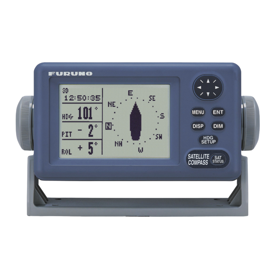
OPERATION Controls MENU key: Opens menu. DISP key: Selects display; closes menu. HOW TO REMOVE THE COVER Press here and pull toward you to remove cover. Omnipad: Selects menu items; shifts cursor. MENU DISP SETUP SATELLITE COMPASS STATUS SAT STATUS key: Shows satellite tracking status. See the illustration on page 1-20. -
Page 36: Turning The Power On/Off
2. OPERATION Turning the Power On/Off Use the power switch on the processor unit to turn the power to the display unit on and off. A beep sounds and the display starts up with the last-used display. Note: If backup heading data is used the heading indication flashes until faithful heading data becomes available. -
Page 37: Choosing A Display
Steering and Compass displays. Nav data display The nav data display shows position in latitude and longitude, speed, heading, date, time and position-fixing status. 2D GPS position fix 3D GPS position fix 2D DGPS position fix Position- 3D DGPS position fix... - Page 38 2. OPERATION Steering display The steering display shows heading in digital and analog form. SOG and COG are also indicated. Note that COG accuracy is low when the own ship speed is low. The faster the speed, the more accurate the COG. Bearing scale Compass display...
- Page 39 Speed display Depending on the setting of DISTANCE DISP on the TRIP menu, the Set and Drift display or the Distance Run display is shown. The current indication requires a Doppler Speed Log. ° CURRENT Current (direction, speed) Ground speed DISTANCE Distance run SOG/STW display...
-
Page 40: Alarm Setup
2. OPERATION Alarm Setup The SC-50 can alert you with audible and visual alarms when GPS signal, DPGS signal and WAAS signal are lost. To set the DGPS alarm, do the following: 1. Press the [MENU] key to show the menu. -
Page 41: Confirming Satellite Status
Confirming Satellite Status You can check the receiving condition of each antenna unit as follows: 1. Press the [MENU] key to open the menu. 2. Choose SATELLITE and then press the [ENT] key. Elevation angle 5 Antenna element 3. Use ◄ or ► to choose antenna element for which to confirm receiving status. 4. -
Page 42: Gps Setup
GPS fix may change randomly, even if the vessel at anchor. This change can be smoothed by averaging a number of GPS fixes. The setting range is from 0 (no smoothing) to 999 seconds. The higher the setting the more smoothing. -
Page 43: Output Data
DISABLE SV (Disable satellite) Every GPS satellite is broadcasting abnormal satellite number(s) in its Almanac, which contains general orbital data about all GPS satellites. Using this information, the GPS receiver automatically eliminates any malfunctioning satellite from the GPS satellite schedule. However, the Almanac sometimes may not contain this information. - Page 44 GLL: Geographic position, latitude/longitude VHW: Water speed and heading VBW: Dual ground/water speed HVE: GPS antenna up-down motion amplitude (FURUNO proprietary sentence) ZDA: Time and date 7. Use the Omnipad to choose OFF or ON as appropriate and then press the [ENT] key.
- Page 45 15. Choose appropriate IEC (or NMEA) edition and then press the [ENT] key. 16. Choose HDG TALKER and then press the [ENT] key. 17. Choose appropriate heading talker and then press the [ENT] key. GP: GPS navigator talker HE: North-seeking gyrocompass talker HN: Non-north seeking gyrocompass talker HC: Magnetic compass talker 18.
- Page 46 2. OPERATION Output sentence limitation The number of sentences which can be output depends on baud rate and output interval settings. The maximum number of characters per each data sentences are shown in the table below and the total number of characters must satisfy the formula shown below.
-
Page 47: Log Pulse
2.8.2 Log pulse This equipment provides SOG (speed over ground) in high accuracy. It converts an SOG value to a pulse signal and outputs at the rate of 200 or 400 pulses/nm. 1. Press the [MENU] key. 2. Choose I/O SETUP and then press the [ENT] key. 3. -
Page 48: System Setup
Your unit is preprogrammed to recognize most of the major chart systems of the world. Although the WGS-84 system (default setting) is the GPS standard, other categories of charts in other datum still exist. Match the GPS datum with the chart system you use. -
Page 49: Units Of Measurement
7. Press the [DISP] key to close the menu. 2.9.3 Using local time GPS uses UTC time. If you would rather use local time, enter the time difference (range: -13:30 to +13:30) between local time and UTC. 1. Press the [MENU] key to open the menu. -
Page 50: Demonstration Mode
2. OPERATION 2.9.5 Demonstration mode The demonstration mode provides simulated operation of the equipment. 1. Press the [MENU] key to open the menu. 2. Choose SYS SETUP and then press the [ENT] key. 3. Choose DEMO and then press the [ENT] key. 4. -
Page 51: Waas/Dgps Setup
DPGS: Position fix by DGPS (external beacon receiver required) AUTO: Position fix in order of DGPS, WAAS and GPS 5. For WAAS or AUTO do as below. For DGPS go to step 6; for GPS go to step 1) WAAS SEARCH is selected; press the [ENT] key. - Page 52 2. OPERATION 2) Use the Omnipad to choose WAAS satellite search method, AUTO or MANUAL as appropriate. For MANUAL, press the [ENT] key, enter appropriate WAAS satellite referring to the illustration below and then press the [ENT] key. Provider WAAS EGNOS 3) CORRECTIONS DATA SET is selected;...
- Page 53 2. OPERATION 3) FREQ is selected; press the [ENT] key. 4) The cursor is selecting the hundredths digit so press ▲ or▼ to display appropriate digit. Press ► to shift the cursor to the tenths place. 5) Set other digits appropriately. 8.
-
Page 54: Others Menu
This is done for safety purposes; for example, when an autopilot is used. HDG BACKUP: Choose how long to display backup data when the GPS signal is lost. (This data is also output to external equipment.) 1. Press the [MENU] key to display the main menu. -
Page 55: Trip Menu
(DRIFT). Press the [ENT] key. 5. Choose DISTANCE CALC and then press the [ENT] key. 6. Choose the source for distance run; GPS, VLW (distance traveled through water) or VBW (Dual ground/water speed). (VLW requires DS-80 type Doppler speed log and VBW requires Current indicator or Doppler speed log.) Press the [ENT] key. -
Page 56: Resetting Distance Run
- - - . - 3. ”HEADING” is selected; press the [ENT] key. 4. Choose INT or EXT as appropriate. Normally choose INT. If own GPS sensor is not working and a heading sensor such as a gyrocompass is available, choose EXT. -
Page 57: Maintenance, Troubleshooting
MAINTENANCE, TROUBLESHOOTING Preventive Maintenance Regular maintenance is important for good performance. A maintenance program should be established and should include the following points. Check connectors and ground terminal on the processor unit and display unit for tightness. Check ground terminal for rust. Clean or replace as necessary. Check for water leakage in the antenna cable. -
Page 58: Troubleshooting
Heading output from SC-50 does not appear on external equipment. If large heading error occurs or heading indication is frequently interrupted, contact your dealer for advice. Troubleshooting... -
Page 59: Diagnostics
Diagnostics Diagnostic test1 The diagnostic test1 checks the equipment for proper operation. Note: Heading is not output during the diagnostic test, and this is communicated with an appropriate message. After completing the diagnostic test, turn the power off and on to update heading data. 1. - Page 60 3. MAINTENANCE, TROUBLESHOOTING ROM, RAM, KEY TEST OK shown for normal; NG (No Good) shown for error GPS receiver Processor unit Display unit OUTPUT TEST (for serviceman) (For serviceman) DISPLAY TEST PROGRAM NUMBER DISPLAY 6. Turn off the processor unit to quit the diagnostic test1.
- Page 61 Diagnostic test2 If the heading indication changes randomly when ship is at anchor or does not change when the ship moves, run the test2 following the procedure below, with the ship at anchor and satellite signal received. Note: Heading is not output during the diagnostic test, and this is communicated with an appropriate message.
- Page 62 3. MAINTENANCE, TROUBLESHOOTING Diagnostic test3 This test checks the buzzer signal/contact for proper operation. 1. Press the [MENU] key to open the menu. 2. Choose SYS SETUP and then press the [ENT] key. 3. Choose TEST? and then press the [ENT] key. 4.
-
Page 63: Program Number
3. Press the [DISP] key to close the program version no. display. Clearing Data You may clear GPS data and system data all at once or individually as follows: 1. Press the [MENU] key to open the menu. 2. Choose ERASE and then press the [ENT] key. -
Page 64: Replacement Of Battery
3. MAINTENANCE, TROUBLESHOOTING Replacement of Battery The processor unit has a battery which stores data when the power is turned off. When the battery voltage is low, the message “BATTERY!” appears on the display. Have a qualified technician replace the battery, following the procedure below. -
Page 65: Replacement Of Fuse
GPS heading error continues for one minute. For example, satellite cannot be acquired because of unfavorable environment. ABORTING CALC! GPS signal lost for one minute. BACKUP ERROR!(DISP) Corrupted backup data found in display unit at power on. BACKUP Corrupted backup data found at ERROR!(PRCSSR) processor unit at power on. - Page 66 Error Message BATTERY ALM! Voltage of battery in processor unit is low. DATA ERR! GPS data (from the GPS receiver in the processor unit) is lost for one minute. Heading output is stopped and the heading indication shows “- - -“.
-
Page 67: Appendix
SYSTEM DATA? ALL BACKUP DATA? TRIP DISTANCE DISP (DSTNC, DRIFT) MENU DISTANCE CALC (GPS, VLW, VBW ) RESET DISTANCE? DRIFT AVG. (0-9999SEC, 10) SMOOTH ROT (0.1 - 30.0, 2.5 (sec)) ROT RANGE (30, 60, 90 ( Default settings in bold italics... -
Page 68: Digital Interface
APPENDIX 2. Digital Interface Output sentences of channel 1 DATA OUT1-5: HDT, HDM, ROT, Patt, Phve, VTG, GGA, GLL, GNS, ZDA, VHW, VBW, VDR DATA OUT 6: AD-10 Transmission interval HDT, HDM, ROT, Patt, Phve: 100 ms VTG, GGA, GLL, GNS, ZDA, VHW, VBW, VDR: 1 s For details see page 2-12. - Page 69 Schematic diagrams Data IN Load requirements Isolation: Optocoupler Input Impedance: 440 ohm Max. voltage: ±15V Data Out 1-6 Output drive capability Max : 10mA APPENDIX AP-3...
- Page 70 PFECatt- True heading, pitching, rolling $PFEC,GPatt,xxx.x,+xx.x,-xx.x<CR><LF> $PFEC,GPatt,xxx.x,+xx.x,-xx.x*hh<CR><LF> GGA - Global positioning system (GPS) fix data Time, position and fix related data for a GPS receiver. Differential reference station ID, 0000-1023 Age of differential GPS data Units of geoidal separation, m...
- Page 71 This sentence is not used in the current version of NMEA and IEC 61162. Some boaters may want the GPS compass to indicate the magnetic heading when the boat is only fitted with a magnetic compass. HDG is calculated by adding a geomagnetic variation to HDT.
- Page 72 APPENDIX VBW - Dual ground/water speed $--VBW,x.x,x.x,A,x.x,x.x,A,x.x,A,x.x,A*hh<CR><LF> | +--- 11 +----- 10 +-------- 9 | +----------- 8 +-------------- 7 | +----------------- 6 +-------------------- 5 | | +------------------------ 4 | +--------------------------- 3 +------------------------------ 2 +---------------------------------- 1 1. Longitudial water speed, knots 2.
- Page 73 2. Distance since reset, nautical miles 3. Checksum VTG - Course over ground and ground speed COG and SOG obtained by processing the GPS signals. $GPVTG, x.x, T, x.x, M, x.x, N, x.x, K, p*hh<CR><LF> Speed, knots Course degrees magnetic...
-
Page 74: Input/Output Ports
200ms, 1s, 2s, selectable), VTG, GGA, GLL, GNS, ZDA, VHW, VBW, VDR : (1s, 2s, selectable) ATT sentence Proprietary sentence or FURUNO sentence Only P sentence : output rate of 25ms, 100ms,200ms, 1s, 2s, selectable ATT sentence – True heading, pitching, rolling $PFEC,GPatt,xxx.x, +xx.x, +xx.x<CR><LF>... - Page 75 Port Terminal Name Label DATA WAGO OUT6 231-304/026-000 LOG/ WAGO ALARM 231-306/026-000 DATA IN WAGO 231-305/026-000 I/O Signal Remarks Heading AD-10 only AD-10 output interval: 25ms 200 pulse/nm or 400 pulse/nm (software), 0.5A max. Signal Heading alarm, 0.5A max, normal close alarm Heading Heading data in either AD-10 or...
-
Page 76: Parts List And Parts Location
This equipment contains complex modules in which fault diagnosis and repair down to component level are not practical (IMO A.694(17)/8.3.1. Only some discrete components are used. FURUNO Electric Co., Ltd. believes identifying these components is of no value for shipboard maintenance; therefore, they are not listed in the manual. Major modules can be located on the parts location photo on this and then next page. - Page 77 F U R U N O ELECTRICAL PARTS LIST SYMBOL TYPE PRINTED CIRCUIT BOARD 20P8189, CPU Model SC-50/110 Unit SC-502 DISPLAY UNIT Ref.Dwg. Blk.No. CODE No. REMARKS Display Unit, cover opened APPENDIX Page SHIPPABLE ASSEMBLY CPU Board (20P8189) AP-11...
-
Page 78: Geodetic Chart Codes
APPENDIX 5. Geodetic Chart Codes 001:WGS84 002:WGS72 003:TOKYO :Mean Vallue (Japan, Korea, and Okinawa) 004:NORTH AMERICAN 1927 :Mean Vallue (CONUS) 005:EUROPEAN 1950 :Mean Vallue 006:AUSTRALIAN GEODETIC 1984 :Australla and Tasmania Island 007:ADINDAN :Mean Value(Ethiopia and Sudan) 008: :Ethiopia 009: :Mall 010:... -
Page 79: Principle Of Satellite Compass
In reality, a third antenna is used to reduce the influence of pitch, roll and yaw, and five satellites are processed to process 3D data. If the GPS signal is blocked by a tall building or the vessel is under a bridge, the 3-axis solid-state angular rate gyros in the processor unit take place of the satellite compass, maintaining the current heading continuously. -
Page 80: What Is Waas
SBAS signal. Furuno will accept no responsibility for the use of the signal for other than the above stated purpose. It is the user’s responsibility to exercise common prudence and navigational judgment while using... -
Page 81: Packing List
PACKING LIST SC-303 N A M E ユニット UNIT GPSアンテナ GPS ANTENNA 工事材料 INSTALLATION MATERIALS 鳥よけ BIRD-REPELLENT FIXTURE バネ座金 SPRING WASHER ミガキ平座金 FLAT WASHER 六角ボルト スリ割 HEX.BOLT (SLOTTED HEAD) ケーブルカバー CABLE COVER 図書 DOCUMENT 型紙 TEMPLATE (略図の寸法は、参考値です。 DIMENSIONS IN DRAWING FOR REFERENCE ONLY.)... - Page 83 工事材料表 工事材料表 工事材料表 工事材料表 INSTALLATION MATERIALS 番 号 名 称 NAME ケーブル組品 ANTENNA CABLE ASSY. (略図の寸法は、参考値です。 DIMENSIONS IN DRAWING FOR REFERENCE ONLY.) (略図の寸法は、参考値です。 DIMENSIONS IN DRAWING FOR REFERENCE ONLY.) (略図の寸法は、参考値です。 DIMENSIONS IN DRAWING FOR REFERENCE ONLY.) (略図の寸法は、参考値です。 DIMENSIONS IN DRAWING FOR REFERENCE ONLY.) 004-379-660 CODE NO. CODE NO.
- Page 84 工事材料表 工事材料表 工事材料表 工事材料表 INSTALLATION MATERIALS 番 号 名 称 NAME アンテナベース組品(S) ANTENNA BASE ASSY.(S) (略図の寸法は、参考値です。 DIMENSIONS IN DRAWING FOR REFERENCE ONLY.) (略図の寸法は、参考値です。 DIMENSIONS IN DRAWING FOR REFERENCE ONLY.) (略図の寸法は、参考値です。 DIMENSIONS IN DRAWING FOR REFERENCE ONLY.) (略図の寸法は、参考値です。 DIMENSIONS IN DRAWING FOR REFERENCE ONLY.) 004-377-570 CODE NO. CODE NO.
- Page 85 工事材料表 INSTALLATION MATERIALS 番 号 名 称 NAME スリーボンド SEALANT 固定用金具S MOUNTING BASE 補助金具 ATTACHMENT PLATE 鳥よけ BIRD-REPELLENT FIXTURE バネ座金 SPRING WASHER ミガキ平座金 FLAT WASHER 六角ナット 1種 HEX.NUT (略図の寸法は、参考値です。 DIMENSIONS IN DRAWING FOR REFERENCE ONLY.) 004-377-590 CODE NO. TYPE CP20-02202 型名/規格 略 図 OUTLINE DESCRIPTIONS 1211 50G CODE NO.
- Page 86 PACKING LIST PACKING LIST PACKING LIST PACKING LIST SC-502-J/E SC-502-J/E SC-502-J/E SC-502-J/E N A M E ユニット ユニット ユニット ユニット UNIT UNIT UNIT UNIT 表示部 DISPLAY UNIT 工事材料 工事材料 工事材料 工事材料 INSTALLATION MATERIALS INSTALLATION MATERIALS INSTALLATION MATERIALS INSTALLATION MATERIALS 工事材料 INSTALLATION MATERIALS 1.コ-ド番号末尾の[**]は、選択品の代表型式/コードを表します。 CODE NUMBER ENDED BY "**" INDICATES THE NUMBER OF TYPICAL MATERIAL. (略図の寸法は、参考値です。...
- Page 87 工事材料表 工事材料表 工事材料表 工事材料表 INSTALLATION MATERIALS 番 号 名 称 NAME +トラスタッピンネジ +TAPPING SCREW (略図の寸法は、参考値です。 DIMENSIONS IN DRAWING FOR REFERENCE ONLY.) (略図の寸法は、参考値です。 DIMENSIONS IN DRAWING FOR REFERENCE ONLY.) (略図の寸法は、参考値です。 DIMENSIONS IN DRAWING FOR REFERENCE ONLY.) (略図の寸法は、参考値です。 DIMENSIONS IN DRAWING FOR REFERENCE ONLY.) 004-380-660 CODE NO. CODE NO.
- Page 88 PACKING LIST PACKING LIST PACKING LIST PACKING LIST SC-501-J/E SC-501-J/E SC-501-J/E SC-501-J/E N A M E ユニット ユニット ユニット ユニット UNIT UNIT UNIT UNIT 演算部 PROCESSOR UNIT 予備品 予備品 予備品 予備品 SPARE PARTS SPARE PARTS SPARE PARTS SPARE PARTS 予備品 SPARE PARTS 工事材料 工事材料 工事材料...
- Page 89 工事材料表 工事材料表 工事材料表 工事材料表 INSTALLATION MATERIALS 番 号 名 称 NAME ケーブルラベル CABLE LABEL 操作レバー TERMINAL OPENER +トラスタッピンネジ +TAPPING SCREW (略図の寸法は、参考値です。 DIMENSIONS IN DRAWING FOR REFERENCE ONLY.) (略図の寸法は、参考値です。 DIMENSIONS IN DRAWING FOR REFERENCE ONLY.) (略図の寸法は、参考値です。 DIMENSIONS IN DRAWING FOR REFERENCE ONLY.) (略図の寸法は、参考値です。 DIMENSIONS IN DRAWING FOR REFERENCE ONLY.) 004-380-560 CODE NO.
- Page 90 OUTLINE PART PART PART PART ヒューズ FUSE MFR'S NAME MFR'S NAME MFR'S NAME MFR'S NAME FURUNO FURUNO FURUNO FURUNO ELECTRIC ELECTRIC ELECTRIC ELECTRIC (略図の寸法は、参考値です。 DIMENSIONS IN DRAWING FOR REFERENCE ONLY.) (略図の寸法は、参考値です。 DIMENSIONS IN DRAWING FOR REFERENCE ONLY.) (略図の寸法は、参考値です。 DIMENSIONS IN DRAWING FOR REFERENCE ONLY.) (略図の寸法は、参考値です。 DIMENSIONS IN DRAWING FOR REFERENCE ONLY.)...
- Page 91 フラッシュマウントキット フラッシュマウントキット フラッシュマウントキット フラッシュマウントキット FLUSH MOUNT KIT. FLUSH MOUNT KIT. FLUSH MOUNT KIT. FLUSH MOUNT KIT. 番 号 名 称 NAME 化粧パネル COSMETIC PANEL +トラスタッピンネジ TAPPING SCREW バネ座金 SPRING WASHER 六角ボルト スリ割り HEX.BOLT(SLOTTED HEAD) (略図の寸法は、参考値です。 DIMENSIONS IN DRAWING FOR REFERENCE ONLY.) (略図の寸法は、参考値です。 DIMENSIONS IN DRAWING FOR REFERENCE ONLY.) (略図の寸法は、参考値です。 DIMENSIONS IN DRAWING FOR REFERENCE ONLY.)...
- Page 92 フラッシュマウントキット フラッシュマウントキット フラッシュマウントキット フラッシュマウントキット FLUSH MOUNT KIT. FLUSH MOUNT KIT. FLUSH MOUNT KIT. FLUSH MOUNT KIT. 番 号 名 称 NAME フラッシュマウント FIXING PLATE FOR FLUSH MOUNT 蝶ナット WING NUT 蝶ボルト WING SCREW バネ座金 SPRING WASHER 六角ボルト スリ割り HEX.BOLT(SLOTTED HEAD) (略図の寸法は、参考値です。 DIMENSIONS IN DRAWING FOR REFERENCE ONLY.) (略図の寸法は、参考値です。 DIMENSIONS IN DRAWING FOR REFERENCE ONLY.)...
- Page 93 Takahashi T Y. Hatai...
-
Page 99: Interconnection Diagram
E.MIYOSHI SC-50 サテライトコンパス TAKAHASHI.T 名称 Y. Hatai 相互結線図 MASS NAME SATELLITE COMPASS INTERCONNECTION DIAGRAM C7251-C01- D FURUNO ELECTRIC CO., LTD. *3 *4 TNC-J-3 空中線部 ANTENNA UNIT SC-603 TNC-J-3 GPS ANT 1 TNC-J-3 GPS ANT 2 TNC-J-3 選択 GPS ANT 3... -
Page 100: Index
DISP key ... 2-3 Distance run display ... 2-4 Distance run resetting... 2-22 Error messages ... 3-9 Fuse replacement... 3-9 Geodetic data... 2-14 GPS setup menu ... 2-8 Heading backup... 2-20 external source for backup... 2-22 output ... 2-9 restoration... 2-20 Heading display...