Furuno SC-50 Operator's Manual
Thd satellite compass
Hide thumbs
Also See for SC-50:
- Operator's manual (101 pages) ,
- Specifications (4 pages) ,
- Product specification (2 pages)
Table of Contents
Advertisement
Quick Links
Advertisement
Table of Contents
Troubleshooting

Related Manuals for Furuno SC-50


Summary of Contents for Furuno SC-50
- Page 1 OPERATOR'S MANUAL THD SATELLITE COMPASS SC-50 MODEL www.furuno.co.jp...
- Page 2 : +81-(0)798-65-4200 A : FEB 2004 All rights reserved. Printed in Japan E1 : FEB . 16, 2010 Pub. No. OME-72510-E1 *00014854814* *00014854814* (DAMI ) SC-50 *00014854814* *00014854814* * 0 0 0 1 4 8 5 4 8 1 4 *...
- Page 3 (http://www.eiae.org/) for the correct method of disposal. How to discard a used battery Some FURUNO products have a battery(ies). To see if your product has a battery(ies), see the chapter on Maintenance. Follow the instructions below if a battery(ies) is used.
- Page 4 Do not remove the label. If the label is missing or navigation of a vessel. damaged, contact a FURUNO agent or dealer Always confirm position against al about replacement. available aids to navigation (incl. nau-...
-
Page 5: Table Of Contents
TABLE OF CONTENTS FOREWORD........................v SYSTEM CONFIGURATION ..................vi EQUIPMENT LIST ......................vii SPECIFICATIONS ..................... SP-1 1 INSTALLATION ....................... 1-1 1.1 Mounting Considerations....................1-1 1.1.1 Antenna unit......................1-1 1.1.2 Display unit, processor unit..................1-3 1.2 Installing the Antenna Unit....................1-4 1.2.1 Antenna unit SC-303 .................... - Page 6 3 MAINTENANCE, TROUBLESHOOTING ............... 3-1 3.1 Preventive Maintenance ....................3-1 3.2 Troubleshooting .........................3-2 3.3 Diagnostics ........................3-3 3.4 Program Number .......................3-7 3.5 Clearing Data ........................3-7 3.6 Replacement of Battery .....................3-8 3.7 Replacement of Fuse......................3-9 3.8 Error Messages........................3-9 APPENDIX ....................... AP-1 1. Menu Tree ........................... AP-1 2.
-
Page 7: Foreword
A Word to the Owner of the SC-50 FURUNO Electric Company thanks you for purchasing the FURUNO SC-50 THD Satellite Compass. (Hereafter, for sake of brevity, we refer to the SC-50 as Satellite Compass.) We are confident you will discover why the FURUNO name has become synonymous with quality and reliability. -
Page 8: System Configuration
SYSTEM CONFIGURATION The SC-50 consists of an antenna, a display unit and a processor unit. The tri-antenna system accommodates three antennas/receiver units and is available in a low-profile radome type or open type. The tri-antenna system helps reduce the influence of ship's motion (rolling). -
Page 9: Equipment List
EQUIPMENT LIST Standard supply Name Type Code No. Remarks SC-303 Radome type GPS Antenna Choose one SC-603 Open type Display Unit SC-502 Processor Unit SC-501 CP20-02230* 004-378-110 TPPX cable CP20-02260* 004-379-660 TNC cable CP20-02231* 004-378-050 For SC-303 For processor unit: CP20-02600 000-041-905... - Page 10 This page intentionally left blank. viii...
-
Page 11: Specifications
FURUNO SPECIFICATIONS OF SATELLITE COMPASS SC-50 GENERAL Heading accuracy 0.5° RMS Heading resolution 0.1° Follow-up 45°/s rate-of-turn Settling time 3 minutes Position accuracy 10 m, or 5 m (DGPS), 95% of the time Heading/Nav data output Number of port AD-10 format specialty: 1 port... - Page 12 FURUNO COATING COLOR Display unit Panel: N3.0, Chassis: 2.5GY5/1.5 Processor unit 2.5GY5/1.5 Antenna unit N9.5 SP - 2 E7251S01D...
-
Page 13: Installation
INSTALLATION Mounting Considerations 1.1.1 Antenna unit General • Keep the length of the antenna cable in mind when selecting a mounting location. Installing the antenna above superstructures • The antenna must be mounted above all other structures on the vessel to obtain an unobstructed view of the satellites regardless of vessel heading. - Page 14 1. INSTALLATION • The horizontal separation between the antenna and masts must be as follows: Mast diameter Separation distance (minimum) 10 cm 1.5 m 30 cm SC-50’s antenna Horizontal separation distance Mast, etc. Mast, etc. ° Less than 10 TOP VIEW Horizontal separation between antenna and masts •...
-
Page 15: Display Unit, Processor Unit
1. INSTALLATION Location influenced Radar Antenna by reflected wave. Reception blocked by mast. SC-series Antenna Bridge Example of antenna installed below superstructures 1.1.2 Display unit, processor unit • Choose a location where vibration and shock are minimal. • Install the units well away from locations subject to rain and water splash. •... -
Page 16: Installing The Antenna Unit
1. INSTALLATION Installing the Antenna Unit 1.2.1 Antenna unit SC-303 Note: “Bird-repellent fixtures” (supplied) may be attached to the antenna cover to prevent birds from alighting on the cover. If it is more convenient to attach them before fixing the antenna unit to the mounting location, do step 9 before fixing the antenna unit. - Page 17 1. INSTALLATION 3. Coat exposed parts of nuts, bolts and washers with silicone sealant. Radome base Platform Coat with silicone sealant. Coating bolt, nut and washers with silicone sealant 4. Connect the three coaxial cables coming from the antenna unit to the appropriate coaxial cables on the antenna cable, referring to the table below.
- Page 18 1. INSTALLATION 8. Set the “cable cover” to the antenna base as shown in the figure below. Cable Cover How to insert the cable cover HOW TO REMOVE CABLE COVER Insert slotted-head screwdriver here to remove cable cover. 9. If necessary, attach nine “bird-repellent fixtures” (supplied) to the antenna cover as shown below.
-
Page 19: Antenna Unit Sc-603
1. INSTALLATION 1.2.2 Antenna unit SC-603 Note: “Bird-repellent fixtures” (supplied) may be attached to each antenna element and the Antenna Cover to prevent birds from alighting on the antenna. If it is more convenient to attach them before fixing the antenna unit to the mounting location, do step 10 in “Welding the antenna unit”... - Page 20 1. INSTALLATION 4. Making sure each antenna element is correctly oriented, fix each with its nut. Write the corresponding arm number on each coaxial cable, using a magic marker. (When connecting with the coaxial cables from the processor unit it is necessary to match correct antenna element number with coaxial cable color.) Arm [1]...
- Page 21 1. INSTALLATION 7. Orient the antenna unit as shown in the illustration below. Antenna Element A number is inscribed on each antenna arm. PORT This is the antenna element number. Antenna Element The bow mark is between antenna element [1] and [2]. Antenna Face the bow mark towards Element...
- Page 22 1. INSTALLATION Welding the antenna unit The antenna unit may be welded to the antenna mast if the satellite status display shows “OK.” 1. Unfasten the coaxial cables and dismount the antenna unit. 2. Weld the pedestal and support plate to the antenna mast. Remove the clamps used to temporarily fasten the pedestal and support plate.
- Page 23 1. INSTALLATION 7. Make a loop in the antenna cable as shown in the illustration below. Fasten the antenna cable to the antenna mast with cable ties. Coat bolt threads with Coat with Three Three Bond. Fasten bolt Bond 1211 (supplied). with nuts and then coat nuts with Three Bond also.
-
Page 24: Installing The Processor Unit
1. INSTALLATION Installing the Processor Unit The processor unit should be mounted aligned with the ship’s fore-and-aft line. It can be mounted on the deck, bulkhead, or on the underside of a desk. Choose a mounting location which allows you to easily view the power lamp on the top of the unit and which is within ±... -
Page 25: Deck Mount
1. INSTALLATION 1.3.2 Deck mount Orient the processor unit as shown below and fix it to the mounting location with four tapping screws (M5x20). You will set the orientation later on the menu. Mount processor unit Reference Direction so reference direction is within ±... -
Page 26: Installation On The Underside Of A Desk
1. INSTALLATION 1.3.3 Installation on the underside of a desk The processor unit may be mounted on the underside of a desk as shown in the figure below. Do not install it on the overhead. Desk Name Plate Installation of processor unit on the underside of a desk Reference Direction Mount processor unit so reference direction is... -
Page 27: Installing The Display Unit
1. INSTALLATION Installing the Display Unit The display unit can be installed on a desktop, overhead, or flush mounted in a console. The optimal viewing distance is 0.5 m. 1.4.1 Desktop, overhead mounting 1. Fasten the hanger to the mounting location with four tapping screws (supplied). - Page 28 1. INSTALLATION Flush mount “S” Flush mount “S” kit Type: OP20-17, Code No.: 000-040-720) Name Type Code No. Flush Mount Fixture 20-007-2401 100-183-190 Wing Bolt M4X30 000-804-799 Wing Nut 000-863-306 Hex Bolt M6X12 000-862-127 Spring Washer 000-864-260 1. Make a cutout in the mounting location. The dimensions are 167(W) x 92(H) 2.
-
Page 29: Wiring
1. INSTALLATION Wiring This section covers general wiring. For further details see the interconnection diagram at the back of this manual. ANTENNA UNIT ANTENNA UNIT SC-603 SC-303 PROCESSOR UNIT SC-501 DPYC 1.5 12-24 VDC TPPX6-3D2V-15M, 15m MJ-A7SPF0006-100, TNC-PS-3D-15 (3 pcs.) DISPLAY UNIT SC-502 GPS ANT... - Page 30 1. INSTALLATION Note 1: Use cable type DPYC-1.5 (or equivalent) for the power cable. DPYC-1.5 Armor Sheath φ = 11.7 mm Conductor S = 1.5 mm φ = 1.56 mm Sectional view of coaxial cable DPYC-1.5 Note 2: The optional antenna cable set (CP20-01700 or CP20-01710) allows you to extend antenna cable length to 30 m (50 m).
- Page 31 1. INSTALLATION How to attach connector N-P-8DFB Outer Sheath Armor Inner Sheath Shield (Dimensions in millimeters.) Cover with heat-shrink tubing and heat. Cut off insulator and core by 10 mm. Twist shield end. Slip on clamp nut, gasket and clamp as shown left. Clamp Clamp Nut Gasket (reddish...
-
Page 32: Initial Settings
1. INSTALLATION Initial Settings Follow the procedures in this section to enter initial settings. NOTICE Improper menu settings may stop output of data and display the message "RATE ERROR." Be sure to enter correct data. 1.6.1 Confirming satellite status Press the [SAT STATUS] key. Satellites used for measurement "OK"... -
Page 33: Choosing Mounting Method
1. INSTALLATION 1.6.2 Choosing mounting method 1. Turn on the processor unit and then press the [MENU] key to show the menu. MAIN MENU SATELLITE ALARMS WAAS/DGPS MESSAGES I/O SETUP GPS SETUP INST MENU SYS SETUP ERASE SOFT VER. TRIP MENU OTHERS Main menu 2. -
Page 34: Connection Of External Equipment
1. INSTALLATION Connection of External Equipment 1.7.1 General wiring All external equipment are terminated on the MAIN Board inside the processor unit. Turn off the power and unfasten four screws to remove the cover. Connect wiring from external equipment referring to the interconnection diagram. Use the terminal opener supplied to open terminal blocks, referring to the instructions below. -
Page 35: Fabrication Of Cables
1. INSTALLATION 1.7.2 Fabrication of cables Cable Sectional view, fabrication Power cable Armor DPCY-1.5 Sheath Armor Sheath equivalent) Cut the sheath. φ = 11.7 mm Conductor S = 1.5 mm φ = 1.56 mm SECTIONAL VIEW Vinyl tape Crimp-on lug Lay in clamp FV1.25-5 where paint... - Page 36 1. INSTALLATION (This page intentionally left blank.) 1-24...
-
Page 37: Operation
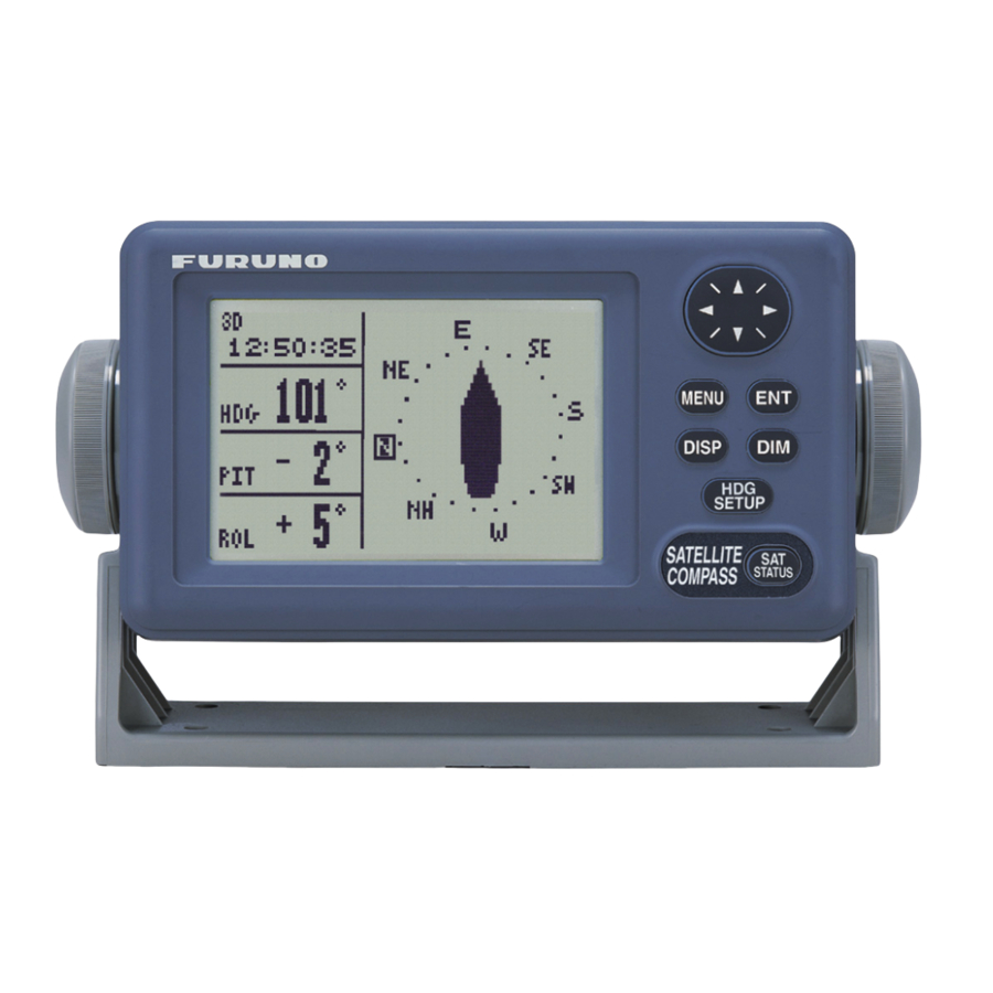
OPERATION Controls MENU key: Opens menu. Omnipad: Selects menu items; shifts cursor. DISP key: Selects display; closes menu. MENU ENT key: Terminates key input. DISP DIM key: Adjusts panel illumination, display contrast. SETUP HDG SETUP key: Chooses heading SATELLITE COMPASS STATUS source. -
Page 38: Turning The Power On/Off
2. OPERATION Turning the Power On/Off Use the power switch on the processor unit to turn the power to the display unit on and off. POWER Switch Processor unit A beep sounds and the display starts up with the last-used display. Note: If backup heading data is used the heading indication flashes until faithful heading data becomes available. -
Page 39: Choosing A Display
2. OPERATION Choosing a Display Use the [DISP] key to show a display desired. 2.4.1 Description of displays Heading display The heading display shows heading, course, speed, date, time and position-fixing status. The heading status mark changes in the sequence shown below. - Page 40 2. OPERATION Steering display The steering display shows heading in digital and analog form. SOG and COG are also indicated. Note that COG accuracy is low when the own ship speed is low. The faster the speed, the more accurate the COG. 07:54:30 °...
- Page 41 2. OPERATION Speed display Depending on the setting of DISTANCE DISP on the TRIP menu, the Set and Drift display or the Distance Run display is shown. The current indication requires a Doppler Speed Log. Ground speed 07:54:30 07:54:30 Lateral speed Speed relative to...
-
Page 42: Alarm Setup
2. OPERATION Alarm Setup The SC-50 can alert you with audible and visual alarms when GPS signal, DPGS signal and WAAS signal are lost. To set the DGPS alarm, do the following: 1. Press the [MENU] key to show the menu. -
Page 43: Confirming Satellite Status
2. OPERATION Confirming Satellite Status You can check the receiving condition of each antenna unit as follows: 1. Press the [MENU] key to open the menu. 2. Choose SATELLITE and then press the [ENT] key. RX signal level Horizontal bar extends with signal strength. -
Page 44: Gps Setup
2. OPERATION GPS Setup The GPS SETUP menu smoothes position and course, averages speed, applies position offset, and deactivates unhealthy satellites. 2.7.1 Displaying the GPS setup menu 1. Press the [MENU] key to open the menu. 2. Choose GPS SETUP and then press the [ENT] key. GPS SETUP SMOOTH POS 0SEC... -
Page 45: Output Data
2. OPERATION DISABLE SV (Disable satellite) Every GPS satellite is broadcasting abnormal satellite number(s) in its Almanac, which contains general orbital data about all GPS satellites. Using this information, the GPS receiver automatically eliminates any malfunctioning satellite from the GPS satellite schedule. However, the Almanac sometimes may not contain this information. - Page 46 GLL: Geographic position, latitude/longitude VHW: Water speed and heading VBW: Dual ground/water speed HVE: GPS antenna up-down motion amplitude (FURUNO proprietary sentence) ZDA: Time and date 7. Use the Omnipad to choose OFF or ON as appropriate and then press the [ENT] key.
- Page 47 2. OPERATION 11. Use the Omnipad to choose the baud rate of the equipment connected and then press the [ENT] key. 12. INTERVAL is selected; press the [ENT] key. 25ms 100ms 200ms 20ms Tx interval options 13. Use the Omnipad to choose appropriate output interval and then press the [ENT] key.
- Page 48 2. OPERATION Output sentence limitation The number of sentences which can be output depends on baud rate and output interval settings. The maximum number of characters per each data sentences are shown in the table below and the total number of characters must satisfy the formula shown below.
-
Page 49: Log Pulse
2. OPERATION 2.8.2 Log pulse This equipment provides SOG (speed over ground) in high accuracy. It converts an SOG value to a pulse signal and outputs at the rate of 200 or 400 pulses/NM. 1. Press the [MENU] key. 2. Choose I/O SETUP and then press the [ENT] key. 3. -
Page 50: System Setup
2. OPERATION System Setup 2.9.1 Geodetic data Your unit is preprogrammed to recognize most of the major chart systems of the world. Although the WGS-84 system (default setting) is the GPS standard, other categories of charts in other datum still exist. Match the GPS datum with the chart system you use. -
Page 51: Units Of Measurement
2. OPERATION 2.9.2 Units of measurement Distance/speed can be displayed in nautical miles/knots, kilometers/kilometers per hour, or miles/miles per hour. 1. Press the [MENU] key to open the menu. 2. Choose SYS SETUP and then press the [ENT] key. 3. Choose UNITS. 4. -
Page 52: Demonstration Mode
2. OPERATION 2.9.5 Demonstration mode The demonstration mode provides simulated operation of the equipment. 1. Press the [MENU] key to open the menu. 2. Choose SYS SETUP and then press the [ENT] key. 3. Choose DEMO and then press the [ENT] key. 4. -
Page 53: Waas/Dgps Setup
2. OPERATION 2.10 WAAS/DGPS Setup 1. Press the [MENU] key to open the menu. 2. Choose WAAS/DGPS and then press the [ENT] key. STATION: Shows GOOD or NG. WAAS/DGPS DATA: Shows GOOD or NG. SIG. S: Signal Strength. A figure be tween 0 MODE and 99 is shown. - Page 54 2. OPERATION 2) Use the Omnipad to choose WAAS satellite search method, AUTO or MANUAL as appropriate. For MANUAL, press the [ENT] key, enter WAAS satellite number, referring to page AP-14 (7. What is WAAS?) and then press the [ENT] key. 3) CORRECTIONS DATA SET is selected;...
-
Page 55: Others Menu
2. OPERATION 2.11 OTHERS Menu The OTHERS menu contains the following items: HOLD HDG DATA: Choose whether to display last-used heading data at power on or not. This data is not reliable. HDG RESTORATION: Choose how to restore GPS signal, automatically or manually, after it is lost. -
Page 56: Trip Menu
2. OPERATION 2.12 TRIP Menu The TRIP menu functions to • Choose the indication to show on the SOG/STW display • Choose source of distance run • Reset distance run to zero • Smooth the tide drift indication • Enter smoothing for rate of turn and display range scale 1. -
Page 57: Resetting Distance Run
1) Never switch from internal to external heading while the autopilot is in the automatic mode. Change to the manual mode before switching. 2) The SC-50 outputs the heading signal from external equipment and, in case of the THS sentence, outputs "mode indicator A". How- ever, the quality of the THS heading signal cannot be guaranteed. - Page 58 This page is intentionally left blank.
-
Page 59: Maintenance, Troubleshooting
MAINTENANCE, TROUBLESHOOTING WARNING ELECTRICAL SHOCK HAZARD Do not open the equipment. Only qualified personnel should work inside the equipment. Preventive Maintenance Regular maintenance is important for good performance. A maintenance program should be established and should include the following points. •... -
Page 60: Troubleshooting
Heading output from Connection between Firmly fasten the SC-50 does not appear on SC-50 and external connector. external equipment. equipment has loosened. Sensor trouble Run the diagnostic test1 to determine the cause. -
Page 61: Diagnostics
3. MAINTENANCE, TROUBLESHOOTING Diagnostics Diagnostic test1 The diagnostic test1 checks the equipment for proper operation. Note: Heading is not output during the diagnostic test, and this is communicated with an appropriate message. After completing the diagnostic test, turn the power off and on to update heading data. 1. - Page 62 3. MAINTENANCE, TROUBLESHOOTING ROM, RAM, KEY TEST OK shown for normal; ROM RAM NG (No Good) shown for error GPS1 PUSH KEY GPS receiver GPS2 KEY TEST GPS3 Press each key one by Processor unit one. Pressed key’s name Display unit DISP appears here if key is functioning properly.
- Page 63 3. MAINTENANCE, TROUBLESHOOTING Diagnostic test2 If the heading indication changes randomly when ship is at anchor or does not change when the ship moves, run the test2 following the procedure below, with the ship at anchor and satellite signal received. Note: Heading is not output during the diagnostic test, and this is communicated with an appropriate message.
- Page 64 3. MAINTENANCE, TROUBLESHOOTING Diagnostic test3 This test checks the buzzer signal/contact for proper operation. 1. Press the [MENU] key to open the menu. 2. Choose SYS SETUP and then press the [ENT] key. 3. Choose TEST? and then press the [ENT] key. TEST1 TEST2 TEST3...
-
Page 65: Program Number
3. MAINTENANCE, TROUBLESHOOTING 3.4 Program Number You may display the program number as follows: 1. Press the [MENU] key to open the menu. 2. Choose SOFT VER. and then press the [ENT] key. SOFTWARE VERSION DISPLAY 205-1342-**.** PROCESS 205-1341-**.** GPS1 4850263*** GPS2 4850263***... -
Page 66: Replacement Of Battery
3. MAINTENANCE, TROUBLESHOOTING Replacement of Battery The processor unit has a battery which stores data when the power is turned off. When the battery voltage is low, the message “BATTERY!” appears on the display. Have a qualified technician replace the battery, following the procedure below. -
Page 67: Replacement Of Fuse
3. MAINTENANCE, TROUBLESHOOTING Replacement of Fuse The 3 A fuse on the POWER Board inside the processor unit protects the equipment from overcurrent and reverse polarity of the power supply. If the fuse blows, have a qualified technician check the fuse. WARNING Use the proper fuse. - Page 68 3. MAINTENANCE, TROUBLESHOOTING Error messages (con’t from previous page) Error Message Meaning Remedy BATTERY ALM! Voltage of battery in processor Have battery replaced at unit is low. earliest convenience. DATA ERR! GPS data (from the GPS receiver Check GPS receiver. in the processor unit) is lost for one minute.
-
Page 69: Appendix
APPENDIX 1. Menu Tree BUZZER (SHORT, LONG, CONSTANT) ALARMS MENU DGPS (OFF, ON) MESSAGES SMOOTH POS (0 SEC) GPS SETUP SMOOTH S/C (5 SEC) LAT OFFSET (0.000’N) LON OFFSET (0.000’E) DISABLE SV DATUM (WGS84, WGS72, OTHER 001 (WGS84)) SYS SETUP UNITS (kn , km/h, mi/h) TIME DIFF (+00:00) TIME DISP (12 HOUR, 24 HOUR) -
Page 70: Digital Interface
APPENDIX 2. Digital Interface Output sentences of channel 1 DATA OUT1-5: HDT, HDM, THS, ROT, Patt, Phve, VTG, GGA, GLL, GNS, ZDA, VHW, VBW, VDR DATA OUT 6: AD-10 Transmission interval HDT, HDM, THS, ROT, Patt, Phve: 100 ms VTG, GGA, GLL, GNS, ZDA, VHW, VBW, VDR: 1 s For details see page 2-12. - Page 71 APPENDIX Schematic diagrams Data IN 20P8178 FL35 R108 PC-40 FL36 1SS27 Load requirements Isolation: Optocoupler Input Impedance: 440 ohm Max. voltage: ±15V Data Out 1-6 20P8178 U1 max3043 Output drive capability Max : 10mA AP-3...
- Page 72 APPENDIX Data sentences PFECatt- True heading, pitching, rolling $PFEC,GPatt,xxx.x,+xx.x,-xx.x<CR><LF> (Ver. 1.5) $PFEC,GPatt,xxx.x,+xx.x,-xx.x*hh<CR><LF> (Ver. 2.0) Checksum (Ver. 2.0) Rolling (output to tenths place) Pitching (output to tenths place) Heading, true (output to tenths place) GGA - Global positioning system (GPS) fix data Time, position and fix related data for a GPS receiver.
- Page 73 APPENDIX GNS - GNNS fix data $--GNS,hhmmss.ss,llll.lll,a,yyyyy.yyy,a,c--c,xx,x.x,x.x,x.x,x.x,x.x*hh<CR><LF> +--- 11 +------ 10 +---------- 9 +-------------- 8 +------------------ 7 | +---------------------- 6 +------------------------- 5 | +------------------------------ 4 +-------+--------------------------------- 3 +---+--------------------------------------------- 2 +------------------------------------------------------------- 1 1. UTC of position 2. Latitude, N/S 3. Longitude, E/W 4.
- Page 74 APPENDIX ROT – Rate of turn ROT derived from a changing rate of GPS compass heading. $--ROT, x.x, A*hh<CR><LF> Status: A = data valid Rate of turn, degrees/min, “-” = bow turns to port VBW - Dual ground/water speed $--VBW,x.x,x.x,A,x.x,x.x,A,x.x,A,x.x,A*hh<CR><LF> | +--- 11 +----- 10 +-------- 9...
- Page 75 APPENDIX VLW - Distance travelled through the water The distance travelled, relative to the water. $--VLW,x.x,N,x.x,N*hh<CR><LF> | +--------- 3 | +---+----------- 2 +---+----------------- 1 1. Total cumulative distance, nautical miles 2. Distance since reset, nautical miles 3. Checksum VTG - Course over ground and ground speed COG and SOG obtained by processing the GPS signals.
-
Page 76: Input/Output Ports
VTG, GGA, GLL, GNS, ZDA, VHW, VBW, VDR : (1s, 2s, selectable) ATT sentence Proprietary sentence or FURUNO sentence Only P sentence : output rate of 25ms, 100ms, 200ms, 1s, 2s, 20ms, selectable ATT sentence – True heading, pitching, rolling $PFEC,GPatt,xxx.x, +xx.x, +xx.x<CR><LF>... - Page 77 APPENDIX Port Terminal Name Signal Remarks Label DATA WAGO Heading AD-10 only OUT6 231-304/026-000 AD-10 output interval: 25ms LOG/ WAGO 200 pulse/NM or 400 pulse/NM (software), ALARM 0.5A max. 231-306/026-000 Signal Heading alarm, 0.5A max, normal close alarm DATA IN WAGO Heading Heading data in either AD-10 or...
-
Page 78: Parts List And Parts Location
This equipment contains complex modules in which fault diagnosis and repair down to component level are not practical (IMO A.694(17)/8.3.1. Only some discrete components are used. FURUNO Electric Co., Ltd. believes identifying these components is of no value for shipboard maintenance; therefore, they are not listed in the manual. Major modules can be located on the parts location photo on this and then next page. - Page 79 APPENDIX F U R U N O Model SC-50/110 Unit SC-502 DISPLAY UNIT ELECTRICAL PARTS LIST Ref.Dwg. Page Blk.No. SYMBOL TYPE CODE No. REMARKS SHIPPABLE ASSEMBLY PRINTED CIRCUIT BOARD 20P8189, CPU CPU Board (20P8189) Display Unit, cover opened AP-11...
-
Page 80: Geodetic Chart Codes
APPENDIX 5. Geodetic Chart Codes :Trinldad and Tobago 001:WGS84 087:MAPARIMA, BWI 002:WGS72 088:NORTH AMERICAN 1927 :Western United States 003:TOKYO :Mean Vallue (Japan, Korea, and Okinawa) 089: :Eastern United States 004:NORTH AMERICAN 1927 :Mean Vallue (CONUS) :Alaska 090: 005:EUROPEAN 1950 :Mean Vallue 091:... -
Page 81: Principle Of Satellite Compass
Difference in range between A1 and A2 is ∆λ + nλ where λ is 19 cm. “n” is automatically found during the initialization stage by receiving three satellites. A fraction of a carrier wavelength, ∆λ, is processed by FURUNO’s advanced kinematic technology in geographical survey, thus determining a vector (range and orientation) A1 to A2. -
Page 82: What Is Waas
APPENDIX 7. What is WAAS? WAAS, available in North and South America mainly, is a provider in the worldwide SBAS (Satellite Based Augmentation System) navigation system. SBAS provides GPS signal corrections to SBAS users, for even better position accuracy, typically better than three meters. -
Page 83: Terminology, Units Of Measurement, Symbols
APPENDIX 8. Terminology, Units of Measurement, Symbols Terminology Term Meaning Automatic Identification System ALARM Alarm Alarm Antenna April ARPA Automatic Radar Plotting Aid August AUTO Automatic Average B-EXT External Beacon ( DGPS Receiver) Bit Per Second CALC GPS baseline Calculation Contour Course Over Ground December... - Page 84 APPENDIX Term Meaning Liquid Crystal Display Latitude/Longitude Longitude Manual March MENU Menu MSAS Multi-Functional Satellite Augmentation System North Navigation Not good NMEA 1.5 NMEA 0183 Version 1.5 November October OFFSET Offset Out/Output Position PRCSSR Processor Unit Power Random Access Memory Read Only Memory Rate of Turn Receive...
- Page 85 APPENDIX Term Meaning West WAAS Wide Area Augmentation System World Geodetic System Units of measurement Unit Meaning ° degree °/min degree/minute decibel kiloHertz kilometer knot meter min or ‘ minute(s) meter/second millisecond Nautical Mile p/NM Pulse/Nautical Mile second(s) AP-17...
- Page 86 APPENDIX Symbols Symbol Meaning Heading Calculation Status, acquiring satellite. See section 2.4.1. Heading Calculation Status, calculating heading. See section 2.4.1. Heading Calculation Status, final calculations. See section 2.4.1. Display last-used heading data at power on or not. See section 2.11. Simulated operation.
- Page 93 Takahashi T Y. Hatai...
-
Page 99: Interconnection Diagram
相互結線図 *5)メニュー切替。 *5. SELECT FROM MENU. Apr.17'07 R.Esumi *6)方位出力が停止したとき、接点回路がオープンになる。 *6. IF THE HEADING OUTPUT STOPS, THE CONTACT CIRCUIT OPENS. SCALE MASS NAME SATELLITE COMPASS *7)ケーブルクランプでアースを取る。 *7. GROUND THROUGH CABLE CLAMP. DWG No. INTERCONNECTION DIAGRAM C7251-C01- F FURUNO ELECTRIC CO., LTD. -
Page 100: Index
INDEX Alarms menu .......... 2-6 Maintenance battery replacement ......3-8 cleaning ..........3-1 Battery replacement ....... 3-8 fuse replacement ........3-9 Menu tree ..........AP-1 Compass display ........2-4 Control description ......... 2-1 Nav data display ........2-3 Data clearing .......... 3-7 OTHERS menu........2-20 Demonstration mode ......