Table of Contents
Advertisement
Advertisement
Table of Contents

Related Manuals for Furuno Satellite Compass SC-50/110


Summary of Contents for Furuno Satellite Compass SC-50/110
- Page 1 SATELLITE COMPASS SC-50/110...
- Page 2 Pub. No. SME-72510-A Pub. No. SME-72510-A ( ( KAOK KAOK ) ) SC-50 SC-50 The paper used in this manual is elemental chlorine free. FURUNO Authorized Distributor/Dealer FURUNO Authorized Distributor/Dealer FIRST EDITION : FIRST EDITION : NOV. NOV. 2005 2005 *00015891300* *00015891300*...
-
Page 3: Table Of Contents
1. Overview ... 1 2. Maintenance Menu ... 2 1 ) MONITOR display ...2 2) COMPASS display ...3 3) R MONITOR display ...3 4) R-CALIB display ...4 5) RATE ERR display ...5 6) OUTPUT display ...5 7) ALARM display ...6 8) ANALOG display ...6 9) ANT MONI display ...6 10) MESSAGE display ...8... -
Page 5: Overview
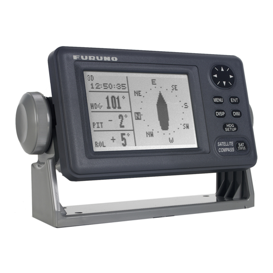
1. Overview The satellite compass, SC-50/110 calculates the heading by using the carrier signal of the GPS satellite signals. The system also calculates the heading with three rate sensors. When the satellite signal is blocked, the system outputs the heading data based on the rate sensor signal for a maximum of 5 minutes. -
Page 6: Maintenance Menu
2. Maintenance Menu The system provides TEC menu or Maintenance menu for servicing. To show TEC menu, press and hold down MENU and ENT keys simultaneously until the menu appears after three beeps. It takes about 8 seconds to hear the third beep. Release the finger from MENU key, and then ENT key. -
Page 7: Compass Display
2) COMPASS display MASK-EL is used to set a minimum elevation angle of the satellite. The satellite of which elevation angle is lower than MASK-EL is not used for heading calculation. Default: 5 degrees. DO NOT change GPS DELAY, TIME CONST, SDEV-S, SDEV-C, and CHK NEW SV. MASK-EL : 05 °... -
Page 8: R-Calib Display
4) R-CALIB display R-CALIB (Rate sensor Calibration) is used to enter the calibration value of the rate sensor at factory. It is not necessary to change this value when the rate sensor is replaced with new one. However, the value on top of the original sensor is written on top of the replacement sensor for future service. -
Page 9: Rate Err Display
5) RATE ERR display This menu sets the level to trigger the heading error alarms; NO HEADING OUTPUT and RATE ERROR. The system compares the output of the angular rate sensor with one obtained by the GPS signal. In the following example, an error is detected when the difference is 2.0º or more. -
Page 10: Alarm Display
7) ALARM display This menu sets the ALARM port signal. When ALARM MODE is set to “STOP,” the alarm signal is not sent out after acknowledgement. When selected “Continue,” the system continues to output the alarm signal. 8) ANALOG display This menu is used to test and compensate the motion sensor output signal. - Page 11 The display consists of four indications; a circular graph which shows direction where the tracking error rate is the highest, a bar graph which shows tracking error rates in 12 directions, mutlipath indexes, and elapsed time. Circular graph: Shows the relation of 12 directions to the bow. The direction of the highest tracking error rate and its opposite direction are painted.
-
Page 12: Message Display
10) MESSAGE display Error messages appear in the display. If RATE ERROR! appears, first check Installation Setup menu for correct setting: “Mounting” method and “Direction.” • NO HEADING OUTPUT ! • HEADING ERROR ! • RATE ERROR ! (YAW) 11) REC MONI menu The REC MONI display, Figure 15 shows whether the system works normally or not. -
Page 13: Replacement Of Battery
3. Replacement of Battery The processor unit has a battery which backs up the RAM contents when the power is removed. When the voltage of the battery drops to 2.5 V, the message “BATTERY!” appears on the screen. To check the message, press [MENU] key and choose “MESSAGE.” The lifetime of the batteries is 3 to 5 years. -
Page 14: Program Upgrade
5. Program Upgrade The three programs are used for the SC-50/110. Two programs are used in the processor unit and one program is in the display unit. The program numbers are tabulated below. Note that the program number of SC-50 is the same as SC-110, but they are different. The program for SC-50 cannot be overwritten by the one for SC-110 in the field and vise versa. -
Page 15: Cpu Board
2) CPU board (Display unit) To upgrade the program on the CPU board; 1. Connect the serial port of the PC to J15 on MAIN board in the processor unit. 2. Turn on the PC. Do not as yet turn on the SC-50/110. 3. -
Page 16: Maintenance
6. Maintenance 6.1 Adjustment 1) PWR board Switching regulator frequency is adjusted on PWR board, 20P8181 as below. Test Point 2) MAIN board Vcc-c supply voltage to Rate sensor is adjusted by VR96 on MAIN board, 20P8178. Test Point #1 of J20 6.2 Line voltage check Line voltages are checked at J3 on the MAIN board. -
Page 17: Location Of Parts
7. Location of Parts Rate Sensor (Default: Roll) Rate Sensor (Default: Pitch) GPS Receivers (1, 2, 3 from Top) Fig. 17 Processor Unit with cover removed TP4 VR80 Rate Sensor (Default: Yaw) Fig.18 PWR Board, 20P8181 VR79 (not shown) PWR Board (20P8181) Main Board (20P8178) - Page 18 Log/Alarm Beacon Ext Roll (above) Data In Pitch J15 for system update CR3 (CPU), Blinking No short bar (for R&D) Fig.19 MAIN Board, 20P8178 Data out 6 Data out 1 to 5 (from right, IEC or AD-10 Heading data) (AD-10) (CR2450-F2ST2L) J20 J19 J18...
-
Page 19: Appendix 1 Protection Of Ics In Data Output Circuit
Appendix 1 Protection of ICs in Data Output Circuit Appendix 1 describes how to prevent ICs in the data output circuit temporarily. Refer to Appendix 2 for permanent remedy. Symptom U1, U2, and U3 in the heading output circuit are damaged. Cause Ground potential difference - The cable shield, or a signal return path between the circuit grounds of the equipment is not connected securely. - Page 20 1. Fabrication of Signal Cable The signal cable is fabricated as below. DO NOT hold back the cable shield over the armor. The installation manual will be revised. Armor Twist and cut. FV1.25-M3 Solder Grounding wire Remove coat for clamping. Armor Twist and cut.
- Page 21 2. Grounding Cable Shield Ground the cable shield or grounding wire to the chassis by using the screw fixing the MAIN board, 20P8178 to the chassis. Fig. 3 Connection of grounding wire...
- Page 22 3. Adding Zener Diodes Zener diodes are added to the data output circuit as below. 1. Fabricate the diode as shown in the figure below. 4 mm Fig. 4 Fabrication of zener diode 2. Remove the coat and solder the diode. See Fig. 5. 3.
- Page 23 Reference) The following waveforms show the effectiveness of the modification. With the SC-50/110 processor unit being not modified, a spike noise is observed at the output terminal on SC-50/110 when the interconnected unit is turned on. (Fig. 6) After modification, the noise is not observed. (Fig. 7) Before modification Condition: SC-50 switched off Measuring points: CH1: TD1-A (pin #1) on DATA 5 port...
-
Page 24: Appendix 2 Modification On Data Output Circuit
Appendix 2 Modification on Data Output Circuit Appendix 1 describes the tentative remedy to prevent U1, U2, and U3 in the heading output circuit from being damaged. Following modification (Table below) is the permanent remedy. The connector is changed from 4 pins to 5 pins for the connection of cable shield. When installing the unit having the current MAIN board (-55);... - Page 25 D - 1...
- Page 26 D - 2...
-
Page 27: Interconnection Diagram, C7251-C01
E.MIYOSHI SC-50 サテライトコンパス TAKAHASHI.T 名称 Y. Hatai 相互結線図 MASS NAME SATELLITE COMPASS INTERCONNECTION DIAGRAM C7251-C01- E FURUNO ELECTRIC CO., LTD. S - 1 *3 *4 TNC-J-3 空中線部 ANTENNA UNIT SC-603 TNC-J-3 GPS ANT 1 TNC-J-3 GPS ANT 2 TNC-J-3 選択... - Page 28 S - 2...
- Page 29 S - 3...
- Page 30 S - 4...