Table of Contents
Advertisement
Quick Links
Advertisement
Table of Contents

Related Manuals for Oki C711cdtn


Summary of Contents for Oki C711cdtn
- Page 1 C610 / C711 User’s Guide...
-
Page 2: Preface
Copyright © 2009. All rights reserved. OKI is a registered trademark of Oki Electric Industry Company, Ltd. Oki Printing Solutions is a trademark of Oki Data Corporation. Energy Star is a trademark of the United States Environmental Protection Agency. -
Page 3: Emergency First Aid
If it gets into the eyes, flush with large amounts of water for at least 15 minutes keeping eyelids open. Seek medical attention. Spillages should be treated with cold water and soap to help reduce risk of staining skin or clothing. ANUFACTURER Oki Data Corporation, 4-11-22 Shibaura, Minato-ku, Tokyo 108-8551, Japan NVIRONMENTAL INFORMATION... -
Page 4: Table Of Contents
ONTENTS Preface ...........2 Emergency first aid . - Page 5 Oki contact details........
-
Page 6: Notes, Cautions And Warnings
OTES CAUTIONS AND WARNINGS NOTE A note provides additional information to supplement the main text. CAUTION! A caution provides additional information which, if ignored, may result in equipment malfunction or damage. WARNING! A warning provides additional information which, if ignored, may result in a risk of personal injury. -
Page 7: About This Guide
BOUT THIS GUIDE NOTE Images used in this manual may include optional features that your product does not have installed. OCUMENTATION SUITE This guide is part of a suite of online and printed documentation provided to help you become familiar with your product and to make the best use of its many powerful features. The documentation is summarised below for reference and is found on the manuals DVD unless indicated otherwise: >... -
Page 8: On-Line Usage
LINE USAGE This guide is intended to be read on screen using Adobe Reader. Use the navigation and viewing tools provided in Adobe Reader. There are many cross-references within this book, each highlighted as blue text. When you click on a cross-reference the display will instantly jump to the part of the manual containing the referenced material. -
Page 9: Introduction
> “Ask Oki” – a user-friendly function for Windows that provides a direct link from your printer driver screen to a dedicated web site specific to the exact model you are using. This is where you’ll find all the advice, assistance and support you could need to help you get the best possible results from your Oki printer. -
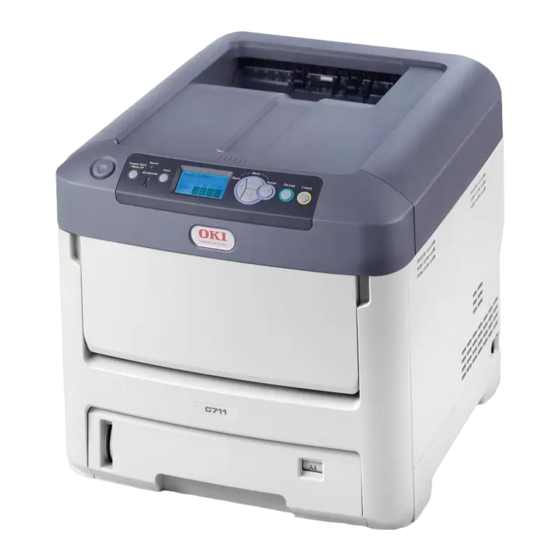
Page 10: Printer Overview
RINTER OVERVIEW RONT VIEW C610 1. Output stacker, face down. 5. Paper level indicator. Standard printed copy delivery point. Holds 6. Front cover release lever. up to 250 sheets at 80g/m². 7. Multi-purpose tray release recess. 2. Operator panel. 8. Top cover release button. Menu driven operator controls and LCD 9. - Page 11 C711 1. Output stacker, face down. 5. Paper level indicator. Standard printed copy delivery point. Holds 6. Front cover release lever. up to 350 sheets at 80g/m². 7. Multi-purpose tray release recess. 2. Operator panel. 8. Top cover release button. Menu driven operator controls and LCD 9.
-
Page 12: Rear View
EAR VIEW This view shows the connection panel, the rear output stacker and the location of the optional duplex (two-sided printing) unit. C610 1. ON/OFF switch. 5. USB interface. 2. AC power socket. 6. ACC interface (host USB). 3. Duplex unit (when fitted). 7. -
Page 13: Changing The Display Language
When the rear paper stacker is folded down paper exits the printer through the rear of the printer and is stacked here face up. This is mainly used for heavy print media. When used in conjunction with the multi purpose feed tray, the paper path through the printer is essentially straight. -
Page 14: Paper Recommendations
APER RECOMMENDATIONS Your printer will handle a variety of print media, including a range of paper weights and sizes, labels and envelopes. This section provides general advice on choice of media, and explains how to use each type. The best performance will be obtained when using standard 75~90g/m² paper designed for use in copiers and laser printers. -
Page 15: Multi Purpose Tray
is enabled in the driver settings. When printing from other systems, this function is enabled in the Print Menu. (See “Menu functions” on page 21.) ULTI PURPOSE TRAY The multi purpose tray can handle the same sizes as the cassette trays but in weights up to 250 . -
Page 16: Loading Paper
OADING PAPER NOTE For illustrative purposes, the C711 printer has been shown. If you have a C610 printer, the principle is the same with any exceptions noted. ASSETTE TRAYS Remove the paper tray from the printer. Fan the paper to be loaded at the edges (1) and in the middle (2) to ensure that all sheets are properly separated, then tap the edges of the stack on a flat surface to make it flush again (3). - Page 17 Load paper (letter headed paper face down and top edge towards the front of the printer), as shown. > Adjust the rear stopper (a) and paper guides (b) to the size of paper being used. CAUTION! C711 ONLY: IMPORTANT: Set paper size dial (c) to the size of paper being used (A4 in the above example).
- Page 18 > Do not pull the paper tray out during printing (except as described below for the 2nd tray). NOTE > If you have two trays and you are printing from the 1st (upper) tray, you can pull out the 2nd (lower) tray during printing to reload it. However, if you are printing from the 2nd (lower) tray, do not pull out the 1st (upper) tray.
-
Page 19: Multi Purpose Tray
ULTI PURPOSE TRAY Open the multi purpose tray (a). Fold out the paper supports (b). Press gently down on the paper platform (c) to ensure it is latched down. Load the paper and adjust the paper guides (d) to the size of paper being used. >... -
Page 20: Operation
PERATION For full details of how to use the machine and any optional accessories to print jobs efficiently and effectively, please refer to the Printing Guide and the Barcode Guide. For full details of how to access and use the printer security features, please refer to the Security Guide. -
Page 21: Menu Functions
ENU FUNCTIONS This section lists the menus accessed via the controls on the printer’s operator panel and displayed in the LCD window. PERATOR PANEL ON: Ready to printing. 1. Ready LED 2. Display Displays the printer status and BLINKING1: Processing data. any error messages. -
Page 22: How To Change The Settings - User
OW TO CHANGE THE SETTINGS USER It should be noted that many of these settings can be, and often are, overridden by settings in the printer drivers. However, several of the driver settings can be left at “Printer Setting”, which will then default to the settings entered in these printer menus. Where applicable, factory default settings are shown in bold type in the following tables. -
Page 23: Configuration Menu
Press the Enter button. Using the up or down MENU button, identify the parameter as required. Press the Enter button to enter an asterisk (*) on the right side of the setting selected. Press the On Line button to switch to online. The machine will automatically re- boot. -
Page 24: Print Information Menu
RINT INFORMATION MENU This menu provides a quick method of listing various items stored within the printer. ITEM ACTION EXPLANATION Configuration Execute Select execute to print out a configuration report. Network Execute Scroll down to this parameter and select execute to print out Network information. -
Page 25: Print Secure Job
RINT SECURE JOB NOTE: This menu only displays if the optional SD card is installed. ITEM ACTION EXPLANATION Encrypted Job Not Found Used for printing an encrypted authentication print job (Encrypted Job) stored in the SD card. Print After inputting a password, “Searching Job” is displayed Delete until a job appropriate for the password is found. -
Page 26: Menus
ENUS ITEM ACTION EXPLANATION Tray Configuration Paper Feed Select tray. Select by scroll and Enter button. Default: Tray 1 Auto Tray Switch Switches Auto ON/OFF. Select by scroll and Enter button. Default: On Tray Sequence Selects Tray sequence Down/Up/Paper feed Tray. - Page 27 ITEM ACTION EXPLANATION Tray Configuration MP Tray Config Configure Paper Size/Media Type/Media (cont.) Weight/Tray Usage. Select by scroll and Enter button. Paper Size: A4/A5/A6/B5/ Legal14/Legal 13.5/Legal13/ Letter/ Executive/ Custom/Com-9 Envelope/Com- 10 Envelope/ Monarch Envelope/DL Envelope/C5/ Index Card Media Type: Plain/ USERTYPE 1 to 5 are displayed only if registered Letterhead/ in the host PC.
- Page 28 ITEM ACTION EXPLANATION System Adjust Power Save Time Select from 1/2/3/4/5/10/15/30/60/ 120/180 Minutes. Default: Select by scroll and Enter button. Sleep Time Select from 1/2/3/4/5/10/15/30/60/ 120/180 Minutes. Default: Select by scroll and Enter button. Clearable Warning Select from: ONLINE/Job. Select by scroll and Enter button.
- Page 29 ITEM ACTION EXPLANATION System Adjust Drum Cleaning Sets whether to rotate the drum in idle prior to (cont.) printing in order to reduce horizontal white Default: lines. Be warned that this will shorten the ID life by as much as this rotation. Select by scroll and Enter button.
-
Page 30: Admin Setup
DMIN SETUP ITEM SETTINGS EXPLANATION Enter xxxxxxxxxxxx Enter a password to gain entry to the Admin Setup menu. Password Password should be from 6 to 12 digits of alpha/numeric characters (or mix) The default value is “aaaaaa” Network TCP/IP Enable Sets TCP/IP Protocol. - Page 31 ITEM SETTINGS EXPLANATION Network Gateway xxx.xxx.xxx.xxx Sets the Gateway (default router) address. Setup Address 0.0.0.0 means that there is no router. (cont.) Display Conditions: > TCP/IP should be enabled. > IP Version is not IPv6. Enable Sets Enable/Disable of Web. Disable Enable: Web/IPP is available.
- Page 32 ITEM SETTINGS EXPLANATION Print Setup Binding Long Edge Specifies Binding in duplex printing. (cont.) Short Edge Display Condition: a duplex unit is installed and enabled. Refer to “Duplex” on page Media Check Enable Sets whether the printer checks the matching of printed data size and that of the tray.
- Page 33 ITEM SETTINGS EXPLANATION Print Setup X Dimension 64 mm Specifies paper width of Custom paper as a default value. (cont.) Sets a paper size at right angles to the paper run direction. 210 mm 216 mm Y Dimension 127 mm Specifies paper length of Custom paper as a default value.
- Page 34 ITEM SETTINGS EXPLANATION PCL Setup A4 Print 78 column Sets the number of characters for A4 paper. (cont.) Width 80 column Auto LF. This is for 10-CPI characters when Auto CR/LF Mode is set to OFF. This menu is enabled only when A4 paper is selected in the menu that sets the print width of A4 paper in portrait orientation.
- Page 35 ITEM SETTINGS EXPLANATION IBM PPR Character 10 CPI Specifies character pitch in IBM PPR emulation. Setup Pitch 12 CPI 17 CPI 20 CPI Proportional Font 12CPI to Specifies 12CPI pitch for Condense Mode. Condense 20CPI 12CPI to 12CPI Character SET-2 Sets a character set.
- Page 36 ITEM SETTINGS EXPLANATION EPSON FX Character 10 CPI/12 CPI/ Specifies character pitch in Epson FX emulation. Setup Pitch 17 CPI 20 CPI/ Proportional Character SET-2 Sets a character set. SET-1 Symbol Set IBM-437 Sets the Symbol Set for Epson FX Emulation. (see machine operator panel for complete list).
- Page 37 ITEM SETTINGS EXPLANATION Memory Receive Auto Sets the size of receive buffer Setup Buffer Size 0.5 megabyte 1 megabyte 2 megabyte 4 megabyte 8 megabyte 16 megabyte 32 megabyte Resource Auto Sets the size of resource saving area. Save 0.5 megabyte 1 megabyte 2 megabyte 4 megabyte...
- Page 38 ITEM SETTINGS EXPLANATION SD Card This item is displayed only if the SD card (option) is installed. Setup Initialize Execute Initializes the SD Card to the factory default setting. Machine performs partition-division, and initializes each partition. When this menu is executed, the following confirmation message appears.
- Page 39 ITEM SETTINGS EXPLANATION System Near Life Enable/Disable Set LCD panel control at the time of near-life warning for setup Status drum, fuser and belt. Enable: Display a near-life warning. Disable: Do not display a near-life warning. Near Life Enable/Disable Controls the settings of the Attention LED when near end of life warning of toner, drum, fuser, or belt occurs.
-
Page 40: Calibration
ITEM SETTINGS EXPLANATION Settings Restore Execute Changes to the menu setting saved. (cont.) Settings When the Enter button is pressed, the following confirmation message appears. Are You Sure? Yes/No If No is selected, the previous menu display resumes. If Yes is selected, changes to the menu settings are saved and this menu is exited. -
Page 41: Boot Menu
OOT MENU This menu should only be changed by the System Administrators. In order to gain access to this menu, follow the instructions in “How to change the settings - administrator” on page This menu is in ENGLISH only (default settings in bold type). Parallel Setup NOTE This menu item is applicable to the C711 only. - Page 42 USB Setup This menu controls the operation of the printer’s USB data interface. ITEM SETTINGS EXPLANATION Enable / Disable ENABLES / DISABLES the USB port. Speed 480 / 12 Mbps Selects the interface speed. After setting change the menu, the printer restarts on exit. Soft Reset Enable / Disable Enables or disables the SOFT RESET command.
- Page 43 ITEM SETTINGS EXPLANATION Reset Cipher Key Execute Resets a cipher key to be used on an encrypted SD card. When this processing is done, all data stored on the SD card cannot be restored. After execution, the following confirmation messages will appear. Are You Sure? If No is selected, the display will return to the previous menu.
- Page 44 Storage setup NOTE This menu only displays if the optional SD card is installed. ITEM SETTINGS EXPLANATION Check File System Execute Resolves mismatch between actual memory and displayed memory available in a file system. Performs administration data (FAT information) recovery. Performs recovery only for an SD Card.
- Page 45 Power setup ITEM SETTINGS EXPLANATION Peak Power Control Normal Sets Peak Power Control level. Sleep Enable Sets Enable/Disable of Sleep Mode. Disable USB Host Power Set power supply for USB-HOST of the whole power save mode. When Off, suppress power supply. When On, do normal power supply.
- Page 46 ITEM SETTINGS EXPLANATION Supplies Report Enable/Disable Indication of frequency of consumable exchange/non indication is set. When Enable is set, also the maintenance counter is indicated in together. Conditions for display: Enable must be selected in Print Statistics > Usage Report. Reset Main Counter Execute The main counter is reset.
-
Page 47: Maintenance
AINTENANCE NOTE For illustrative purposes, the C711 printer has been shown. If you have a C610 printer, the principle is the same. EPLACING CONSUMABLE ITEMS Only use genuine original consumables to ensure the best quality and performance from your hardware. Non original products may adversely affect your printer's performance and invalidate your warranty. - Page 48 Note the positions of the four cartridges. 1. Cyan cartridge 2. Magenta cartridge 3. Yellow cartridge 4. Black cartridge Pull the coloured toner release lever on the cartridge to be replaced fully towards the front of the printer. Lift the right-hand end of the cartridge and then draw the cartridge to the right to release the left-hand end as shown, and withdraw the toner cartridge out of the printer.
- Page 49 Gently shake the new cartridge from end to end several times to loosen and distribute the toner evenly inside the cartridge. Remove the wrapping material and peel off the adhesive tape from the underside of the cartridge. Holding the cartridge by its top centre with the coloured lever to the right, lower it into the printer over the image drum unit from which the old cartridge was removed.
-
Page 50: Image Drum Replacement
Gently wipe the LED head surface with a clean, lint free cloth. Finally, close the top cover and press down firmly at both sides so that the cover latches closed. MAGE DRUM REPLACEMENT CAUTION! Static sensitive devices, handle with care. The printer contains four image drums: cyan, magenta, yellow and black. - Page 51 Note the positions of the four toner cartridges (a) and image drums (b). It is essential that they go back in the same order. Holding it by its top centre, lift the image drum, complete with its toner cartridge, up and out of the printer.
- Page 52 Lift the right-hand end of the toner cartridge (1) and then draw the cartridge to the right to release the left-hand end as shown (2), and withdraw the toner cartridge out of the image drum cartridge. Place the cartridge on a piece of paper to avoid marking your furniture.
-
Page 53: Replacing The Transfer Belt Unit
Holding the complete assembly by its top centre, lower it into place in the printer, locating the pegs at each end into their slots in the sides of the printer cavity. Finally, close the top cover and press down firmly at both sides so that the cover latches closed. - Page 54 Lift each of the image drum units out of the printer and place them in a safe place away from direct sources of heat and light. CAUTION! The green image drum surface at the base of each cartridge is very delicate and light sensitive.
-
Page 55: Fuser Replacement
Lower the new belt unit into place, with the lifting bar at the front and the drive gear towards the rear of the printer. Locate the drive gear into the gear inside the printer by the rear left corner of the unit, and lower the belt unit flat inside the printer. Turn the two fasteners (a) 90°... - Page 56 Pull the two fuser retaining levers (b) towards the front of the printer so that they are fully upright. Holding the fuser by its handle (a), lift the fuser straight up and out of the printer. If the fuser is still warm, place it on a flat surface which will not be damaged by heat. Remove the new fuser from its packaging and remove the transit material.
-
Page 57: Cleaning The Led Head
LEANING THE HEAD Clean the LED heads when printing does not come out clearly, has white lines or when text is blurred. There is no need to switch off the printer to clean the lens. Press the cover release and open the printer’s top cover fully. Gently wipe the LED head surface with a clean, lint free cloth. -
Page 58: Installing Upgrades
NSTALLING UPGRADES NOTE For illustrative purposes, the C711 printer has been shown. If you have a C610 printer, the principle is the same. This section explains how to install optional equipment into your printer. This includes: > duplex (two-sided printing) unit >... -
Page 59: Memory Upgrade
EMORY UPGRADE The basic printer model comes equipped with 256MB of main memory. This can be upgraded with an additional memory board of 256MB or 512MB, giving a maximum total memory capacity of 768MB. Switch the printer off and disconnect the AC power cable. Press the cover release and open the printer’s top cover fully. - Page 60 Carefully remove the new memory board from its wrapping. Try to handle the board only by its short edges, avoiding contact with any metal parts as far as possible. In particular, avoid touching the edge connector. Notice that the memory board has a small cutout in the edge connector, which is closer to one end than the other.
- Page 61 Close the front cover, and close the top cover, pressing down firmly at each side to latch it closed. Reconnect the AC power cable and switch the printer on. When the printer is ready, print a menu map as follows: Press the Enter button.
-
Page 62: Sd Card
CARD The optional SD card enables collating of printed pages and can be used to store overlays and macros, fonts, and secure or proof documents waiting to be printed. Switch the printer off and disconnect the AC power cable. Press the cover release and open the printer’s top cover fully. WARNING! If the printer has been powered on recently, the fuser will be hot. - Page 63 Notice that the SD card has one chamfered corner. Gently push the SD card into the slot as shown. Locate the retaining clips at the bottom of the side cover into their rectangular holes near the bottom of the printer. Close the top of the side cover up to the printer and refit the securing screw loosened in step 4.
-
Page 64: Additional Paper Tray(S)
DDITIONAL PAPER TRAY Switch the printer off and disconnect the AC power cable. Place additional paper tray(s) on desired location. Observing safety rules for lifting and, using locating guides, place printer on top of the additional paper tray(s). Re-connect the AC power cable and switch the printer ON. All that remains is to adjust the printer driver to make full use of the new features (“Setting the driver device options”... -
Page 65: Setting The Driver Device Options
ETTING THE DRIVER DEVICE OPTIONS Once your new upgrade has been installed, you may need to update the printer driver so that the additional features are available to your applications. Accessories such as additional paper trays will only be usable if the printer driver on your computer knows they are there. -
Page 66: Storage Cabinet
Panther (Mac OS X 10.3) Open the Mac OS X Print & Fax Preferences. Click Printing. Click Set Up Printers…. Ensure your machine is selected and click Show Info…. Click the menu and choose Installable Options…. Select all hardware options appropriate to your machine and click Apply Changes…. -
Page 67: Troubleshooting
ROUBLESHOOTING Provided that you follow the recommendations in this guide on the use of print media, and you keep the media in good condition prior to use, your printer should give years of reliable service. However, paper jams occasionally do occur, and this section explains how to clear them quickly and simply. -
Page 68: Paper Sensor Error Codes
APER SENSOR ERROR CODES 380, 400 CODE # LOCATION CODE # LOCATION Paper exit Duplex unit Duplex unit Duplex unit MP Tray Duplex unit Paper Tray Duplex unit Paper feed Paper tray Paper path Paper size a. If fitted. Troubleshooting > 68... -
Page 69: Clearing Paper Jams
LEARING PAPER JAMS NOTE For illustrative purposes, the C711 printer has been shown. If you have a C610 printer, the principle is the same. If a sheet is well advanced out of the top of the printer, simply grip it and pull gently to draw it fully out. - Page 70 he assembly down gently onto a piece of paper to prevent toner from marking Put t your furniture and to avoid damaging the green drum surface, and cover. CAUTION! The green image drum surface at the base of the Image Drum is very delicate and light sensitive.
- Page 71 Look into the printer to check whether any sheets of paper are visible on any part of the belt unit. CAUTION! Do not use any sharp or abrasive objects to separate sheets from the belt. This may damage the belt surface. To remove a sheet with its leading edge at the front of the belt (a), carefully lift the sheet from the belt and pull it forwards into the internal drum cavity and withdraw the sheet.
- Page 72 through the drum cavity area. Then allow the pressure release lever to rise again. NOTE If the sheet is well advanced into the fuser (only a short length is still visible), do not attempt to pull it back. To remove a sheet in the fuser, push the two retaining levers (e) towards the rear of the printer to release the fuser.
- Page 73 Starting with the cyan image drum unit nearest the fuser, replace the four image drums into the drum cavity, making sure to locate them in the correct order. Holding the complete assembly by its top centre, lower it into place in the printer, locating the pegs at each end into their slots in the sides of the printer cavity.
- Page 74 If a duplex unit is fitted, lift lever (j) and lower the duplex unit cover and pull out any sheets found in this area. Close the duplex unit cover Pull down the MP Tray using the depressions. Lift the front cover release lever and lower the front cover.
-
Page 75: Specifications
PECIFICATIONS C610 - N31193B C711 - N31194B ITEM SPECIFICATION Dimensions C610: 435 x 547 x 340mm (W x D x H) without duplex unit C711: 435 x 547 x 389mm (W x D x H) without duplex unit Weight C610: 26Kg approx. (without duplex unit) C711: 27.6Kg approx. -
Page 76: Index
NDEX Belt Operator Panel ...... 21 how to replace ....53 Paper Cleaning the LED head jam clearing ..57 ..... 67 jam, error codes ....68 loading cassette trays ..16 Duplex loading letterhead .... 17 how to install recommended types .... -
Page 77: Oki Contact Details
8 Antares Place Rosedale, Auckland, New Zealand Tel:(64) 9 477 0500 Fax:(64) 9 477 0549 http://www.comworth.co.nz Oki Data(S) P Ltd. Malaysia Rep Office Suite 21.03, 21st Floor Menara IGB, Mid Valley City, Lingkaran Syed Pura 59200, Kuala Lumpur, Malaysia Tel: (60) 3 2287 1177 Fax: (60) 3 2287 1166 Oki contact details >... - Page 78 Oki Data Corporation 4-11-22 Shibaura, Minato-ku,Tokyo 108-8551, Japan www.okiprintingsolutions.com 44550501EE Rev2...