Table of Contents
Advertisement
Quick Links
NF835A Series
User's Manual
NO.: G03-NF835A-F
Revision: 1.0
Release date: January 21, 2021
Trademark:
* Specifications and Information contained in this documentation are furnished for information use only, and are
subject to change at any time without notice, and should not be construed as a commitment by manufacturer.
Advertisement
Table of Contents

Related Manuals for JETWAY NF835A Series


Summary of Contents for JETWAY NF835A Series
- Page 1 NF835A Series User’s Manual NO.: G03-NF835A-F Revision: 1.0 Release date: January 21, 2021 Trademark: * Specifications and Information contained in this documentation are furnished for information use only, and are subject to change at any time without notice, and should not be construed as a commitment by manufacturer.
- Page 2 Environmental Protection Announcement Do not dispose this electronic device into the trash while discarding. To minimize pollution and ensure environment protection of mother earth, please recycle.
-
Page 3: Table Of Contents
TABLE OF CONTENT ENVIRONMENTAL SAFETY INSTRUCTION................... iv USER’S NOTICE............................ v MANUAL REVISION INFORMATION....................v ITEM CHECKLIST..........................v CHAPTER 1 INTRODUCTION OF THE MOTHERBOARD FEATURE OF MOTHERBOARD..................1 SPECIFICATION........................2 LAYOUT DIAGRAM.......................3 CHAPTER 2 HARDWARE INSTALLATION JUMPER SETTING........................ 8 CONNECTORS AND HEADERS..................12 2-2-1 CONNECTORS......................12 2-2-2... -
Page 4: Environmental Safety Instruction
Environmental Safety Instruction Avoid the dusty, humidity and temperature extremes. Do not place the product in any area where it may become wet. 0 to 60 centigrade is the suitable temperature. (The figure comes from the request of the main chipset) ... -
Page 5: User's Notice
USER’S NOTICE COPYRIGHT OF THIS MANUAL BELONGS TO THE MANUFACTURER. NO PART OF THIS MANUAL, INCLUDING THE PRODUCTS AND SOFTWARE DESCRIBED IN IT MAY BE REPRODUCED, TRANSMITTED OR TRANSLATED INTO ANY LANGUAGE IN ANY FORM OR BY ANY MEANS WITHOUT WRITTEN PERMISSION OF THE MANUFACTURER. -
Page 6: Chapter 1 Introduction Of The Motherboard
Chapter 1 Introduction of the Motherboard 1-1 Feature of Motherboard Onboard Intel ® Whiskey Lake-U series processor, TDP 15 W, never denies high performance Support 2* DDR4 2400MHz SO-DIMM, maximum capacity up to 32GB Onboard 2 * RJ-45 gigabit Ethernet LAN port ... -
Page 7: Specification
1-2 Specification Spec Description Design 3.5”SBC; 8-Layers; PCB size: 14.8x 10.2 cm Integrated with Intel ® Whiskey Lake-U series CPU (TDP 15W) Embedded * Note: CPU model varies from different IPC options. Please consult your dealer for more information of onboard CPU. 2*DDR4 SO-DIMM slot support 2* DDR4 2400MHz non-ECC ... -
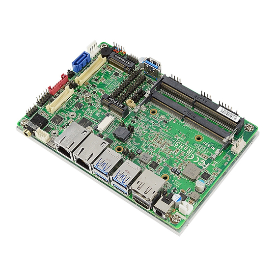
Page 8: Layout Diagram
1* Front panel header 1* 9-pin USB 2.0 header (Expansible to 2* USB 2.0 ports) 1* 4-pin USB 2.0 header (Expansible to 1* USB 2.0 port) 6* Serial port header (COM1~COM6;COM1 supports RS232/422/485) 1* Front panel audio header(No Function) ... - Page 9 Diagram-Front Side: *Front Panel Audio Header GPIO Port SATA Power-out SATAIII Port (No Function) Header Connector INVERTER *Line-out Port Front Panel (No Function) Header (JW_FP1) *Speaker Header LVDS Header EDP Header (No Function) M.2 M-key Slot USB 2.0 Header (M2M) USB 3.1 (Gen.2) Type-C Port Serial Port Headers...
- Page 10 Jumper Positions: JBAT AT_COPEN...
- Page 11 Jumpers Jumper Name Description COM1 Header Pin-9 Function Select 4-Pin Block COM2 Header Pin-9 Function Select 4-Pin Block LCD_ BACKLIGHT VCC Select 4-Pin Block LCD Panel VCC Select 4-Pin Block JBAT Pin (1-2): Clear CMOS 4-Pin Block Pin (3-4): Flash Override AT_COPEN Pin (1-2): AT Mode Select 4-Pin Block Pin (3-4): Case Open Display Select...
- Page 12 Headers Header Name Description JW_FP Front Panel Header(PWR LED/ 9-pin Block HDD LED/Power Button /Reset) FP_USB22 USB 2.0 Header 9-pin Block FP_USB21 USB 2.0 Header 4-pin Block GPIO GPIO Port Header 10-pin Block COM1~COM6 Serial Port Header 9-pin Block EDP Port Header 40-pin Block LVDS LVDS Port Header...
-
Page 13: Chapter 2 Hardware Installation
Chapter 2 Hardware Installation 2-1 Jumper Settings JP1 (4-pin): COM1 Header Pin-9 Function Select COM1 Header → COM1 1 3 5 1 3 5 3-4 Closed: 4-6 Closed: 2-4 Closed: RI= +5V; RI= +12V. RI=RS232; JP2 (4-pin): COM2 Header Pin-9 Function Select COM2 Header →... - Page 14 JP3 (4-pin): LVDS/EDP LCD_BACKLIGHT Voltage Select JP4 (4-pin): LVDS/EDP LCD Panel VCC Select...
- Page 15 Pin (1-2) of JBAT (4-pin): Clear CMOS Settings Pin 1&2 of JBAT → Clear CMOS Pin1 1-2 Open: Normal(Default); JBAT Pin1 1-2 Closed: Clear CMOS(One Touch). Pin (3-4) of JBAT (4-pin): ME Flash Override Select Pin 3&4 of JBAT → ME Flash Override Pin1 3-4 Open: Normal(Default);...
- Page 16 Pin (1-2) of AT_COPEN (4-pin): ATX Mode/AT Mode Select Pin 1&2 of AT_COPEN → ATX/AT Mode Select Pin1 1-2 Open: ATX Mode Selected(Default); AT_COPEN Pin1 1-2 Closed: AT Mode Selected. *ATX Mode Selected: Press power button to power on after power input ready; AT Mode Selected: Directly power on as power input ready.
-
Page 17: Connectors And Headers
Detect’ function. In this case if your case is removed, next time when you restart your computer, a message will be displayed on screen to inform you of this. Connectors and Headers 2-2-1 Connectors (1) Rear I/O Connectors * Refer to Page-3 Rear IO Diagram. Icon Name Function... - Page 18 (2) DC2P(2-pin) : Internal 9~24V DC-in Power Connector Pin1 Pin No. Definition +9V~24VC DC-In DC2P Warning: Find Pin-1 position before connecting power cable to this 2-pin power connector. WRONG INSTALLATION DIRECTION WILL DAMAGE THE BOARD!! (3) SATA(7-pin): SATAIII Port connector This is a high-speed SATAIII port that supports 6GB/s transfer rate.
- Page 19 (4) SATAPWR (4-pin): SATA HDD Power-Out Connector SATAPWR Pin1 Warning: Make sure that Pin-1 of compatible SATA Power out connector is inserted into corresponding Pin-1 of SATAPWR connector to avoid possible damage to the board and hard disk driver! (5) CPUFAN (4-pin): CPU FAN Connector CPUFAN Pin1...
- Page 20 M2M: M.2 M-key Slot M2M M.2 M-Key slot supports compatible type 2242/2260/2280 SATA module. M2M Slot: M.2 Module Installation Guide Nut Location Card Length 4.2 cm 6 cm 8 cm Module Type Type- 2242 Type- 2260 Type- 2280 a) Remove the screw post and nut fixed at b) Lock the screw post into the location location MH1 by default (Skip step 2 &...
-
Page 21: Headers
c) Align and insert corresponding M.2 d) Tighten up the screw to secure the module, as the photo shows. module into the M.2 connector. Make sure not overtighten the screw to avoid possible damage to the module. 2-2-2 Headers JW_FP (9-pin): Front Panel Header JW_FP RSTSW PWRBTN... - Page 22 FP_USB22 (9-pin): USB 2.0 Port Header FP_USB22 +DATA +DATA -DATA -DATA Pin 1 FP_USB21 (4-pin): USB2.0 Header +DATA -DATA FP_USB21 Pin 1...
- Page 23 GPIO (10-pin): GPIO Header GPIO Pin1 I2C_CON (4-pin): I2C Header I2C_SDA I2C_CON I2C_SCL Pi n1...
- Page 24 COM1/2/3/4/5/6(9-pin): Serial Port Headers COM1: RS232/422/485 Serial Port Header. COM2/3/4/5/6: RS232 Serial Port Header. Pin NO. RS232 *RS422 *RS485 (optional) (optional) Pin 1 DATA- COM4 Pin 2 DATA+ COM2 Pin 3 Pin 4 COM6 Pin 5 *COM1 Pin 6 Pin 7 Pin 8 COM5 Pin 9...
- Page 25 EDP (40-pin): 4-lane eDP Header Pin 40 Pin 20 Pin 1 Pin21 Pin Define Pin NO. Pin NO. Pin Define Pin 40 Pin 20 LCD_VCC BL_PWR Pin 39 Pin 19 LCD_VCC BL_PWR Pin 38 Pin 18 LCD_VCC BL_PWR Pin 37 Pin 17 BL_PWR Pin 36...
- Page 26 LVDS (30-pin): 24-bit Dual Channel LVDS Header Pin 1 Pin 2 LVDS Pin 30 Pin29 Pin Define Pin NO. Pin NO. Pin Define LVDSB_DATAN3 Pin 1 Pin 2 LVDSB_DATAP3 LVDS_CLKBN Pin 3 Pin 4 LVDS_CLKBP LVDSB_DATAN2 Pin 5 Pin 6 LVDSB_DATAP2 LVDSB_DATAN1 Pin 7...
- Page 27 INVERTER (8-pin): LVDS Inverter Connector Pin No. Definition Backlight Enable INVERTER Backlight PWM PVCC PVCC Backlight Up SW Backlight Down SW Warning! Find Pin-1 location of the inverter and make sure that the installation direction is correct! Otherwise serious harm will occur to the board/display panel!! PS2KBMS (6-pin): PS/2 Keyboard &...
- Page 28 LAN_LED (4-pin): LAN Activity LED Header LAN_LED Pin1 LAN1LED+ LAN1LED- LAN2LED- LAN2LED+ WLAN_LED (4-pin): Wi-Fi & Bluetooth Activity LED Header WLAN_LED Pin1 WIFI_LED+ WIFI_LED- BT_LED- BT_LED+...
-
Page 29: Chapter 3 Introducing Bios
Chapter 3 Introducing BIOS Notice! The BIOS options in this manual are for reference only. Different configurations may lead to difference in BIOS screen and BIOS screens in manuals are usually the first BIOS version when the board is released and may be different from your purchased motherboard. Users are welcome to download the latest BIOS version form our official website. -
Page 30: Bios Menu Screen
BIOS Menu Screen The following diagram show a general BIOS menu screen: Menu Bar Current Setting Value General Help Items Menu Items Function Keys Function Keys In the above BIOS Setup main menu of, you can see several options. We will explain these options step by step in the following pages of this chapter, but let us first see a short description of the function keys you may use here: ... -
Page 31: Getting Help
Press <+>/<–> keys when you want to modify the BIOS parameters for the active option. [F1]: General help. [F2]: Previous value. [F3]: Optimized defaults. [F4]: Save & Exit. Press <Esc> to quit the BIOS Setup. Getting Help Main Menu The on-line description of the highlighted setup function is displayed at the top right... -
Page 32: Main Menu
Main Menu Main menu screen includes some basic system information. Highlight the item and then use the <+> or <-> and numerical keyboard keys to select the value you want in each item. System Date Set the date. Please use [Tab] to switch between date elements. System Time Set the time. -
Page 33: Advanced Menu
3-7 Advanced Menu Connectivity Configuration Press [Enter] to view current Connectivity related options: CNVi Configuration CNVi Mode This option configures connectivity options. The optional settings are: [Disable Integrated]; [Auto Detection]. [Auto Detection] means that if Discrete solution is discovered it will be enabled by default. - Page 34 The optional settings: [Disabled]; [Enabled]. When set as [Disabled] only one thread per enabled core is enabled. [Enabled]: for Windows and Linux (OS optimized for Hyper-Threading Technology). [Disabled]: for other OS (OS optimized not for Hyper-Threading Technology). *Note: ‘Hyper-Threading’ item may or may not show up, depending on different CPU.
- Page 35 SATA Port The optional settings: [Disabled]; [Enabled]. Use this item to enable or disable each SATA port. Hot Plug The optional settings: [Disabled]; [Enabled]. Port The optional settings: [Disabled]; [Enabled]. Use this item to enable or disable device connected to M.2 SATA slot. ...
- Page 36 The optional settings: [None]; [TPM Clear]. *Note: Your computer will reboot to change State or Security Device. TPM2.0 UEFI Spec Version Use this item to select the TCG2 Spec. Version Support. The optional settings: [TCG_1_2]; [TCG_2]. ACPI Settings Press [Enter] to make settings for the following sub-item: ACPI Settings ACPI Sleep State Use this item to select the highest ACPI sleep state the system will enter when the...
- Page 37 * Note: This function is supported when ‘ERP Support’ is set as [Disabled]. USB S5 Power Use this item to enable or disable USB power after power shutdown. * Note: This function is supported when ‘ERP Support’ is set as [Disabled]. Internal USB Port S5 Power Use this item to enable or disable USB power after power shutdown.
- Page 38 Use this item to enable or disable serial port (COM). Change Settings Use this item to select an optimal setting for super IO device. Changing setting may conflict with system resources. WatchDog Reset Timer Use this item to enable or disable WDT reset function. The optional settings: [Disabled];...
- Page 39 When set as [Enabled], the following sub-items shall appear: CPUFAN Full-Speed Temperature Use this item to set CPUFAN full speed temperature. Fan will run at full speed when above the preset temperature. CPUFAN Full-Speed Duty Use this item to set CPUFAN full speed duty. Fan will run at full speed when above the pre-set duty.
- Page 40 [VT100+]: Extends VT100 to support color, function keys, etc.; [VT-UTF8]: Uses UTF8 encoding to map Unicode chars onto 1 or more bytes. Bits per second Use this item to select serial port transmission speed. The speed must be matched on the other side. Long or noisy lines may require lower speeds. The optional settings: [9600];...
- Page 41 The optional settings: [Disabled]; [Enabled]. Resolution 100x31 Use this item to enable or disable extended terminal resolution. The optional settings: [Disabled]; [Enabled]. Putty KeyPad Use this item to select FunctionKey and KeyPad on Putty. The optional settings: [VT100]; [LINUX]; [XTERMR6]; [SCO]; [ESCN]; [VT400]. Legacy Console Redirection ...
- Page 42 Console Redirection Settings The settings specify how the host computer and the remote computer (which the user is using) will exchange data. Both computers should have the same or compatible settings. Press [Enter] to make settings for the following items: Out-of-Band Mgmt Port The optional settings are: [COM1];...
- Page 43 The default setting is: [1]. *This item may or may not show up, depending on different configuration. USB Configuration Press [Enter] to make settings for the following sub-items: USB Configuration Legacy USB Support The optional settings are: [Enabled]; [Disabled]; [Auto]. [Enabled]: To enable legacy USB support.
- Page 44 taken from hub descriptor. Select [Manual] you can set value for the following sub-item: ‘Device Power-up Delay in Seconds’. Device Power-up Delay in Seconds The delay range is from [1] to [40] seconds, in one second increments. Network Stack Configuration Press [Enter] to go to ‘Network Stack’...
- Page 45 Network This option controls the execution of Network OpROM. The optional settings are: [Do not launch]; [Legacy]. Storage This option controls the execution of UEFI and Legacy Storage OpROM. The optional settings are: [Do not launch]; [UEFI]; [Legacy]. Other PCI devices This item determines OpROM execution policy is for devices other than Network, storage or video.
-
Page 46: Chipset Menu
3-8 Chipset Menu System Agent (SA) Configuration Press [Enter] to make settings for the following sub-items: VT-d The optional settings are: [Enabled]; [Disabled]. ► Memory Configuration Press [Enter] to view brief information for the working memory module. ► Graphics Configuration Press [Enter] to make further settings for Graphics Configuration. - Page 47 *Note: In the case that the ‘Primary IGFX Boot Display’ is select as [DP], [HDMI], or [eDP/LVDS], user can make further settings in ‘Secondary IGFX Boot Display’: Secondary IGFX Boot Display Use this item to select the secondary Display device. The optional settings are: [Disabled];...
- Page 48 24bit Single]; [1280 x 768 24bit Single]; [1280 x 800 18bit Single]; [1280 x 800 24bit Single]; [1366 x 768 18bit Single]; [1366 x 768 24bit Single]; [1440 x 900 18bit Dual]; [1440 x 900 24bit Dual]; [1280 x 1024 24bit Dual]; [1680 x 1050 24bit Dual];...
-
Page 49: Security Menu
Speed The optional settings are: [Auto]; [Gen1]; [Gen2]. M2M Slot Use this item to enable or disable M2M slot PCI Express root port function. The optional settings are: [Disabled]; [Enabled]. *When set as [Enabled], user can make further settings in ‘Speed’: Speed The optional settings are: [Auto];... - Page 50 Security menu allow users to change administrator password and user password settings. Administrator Password If there is no password present on system, please press [Enter] to create new administrator password. If password is present on system, please press [Enter] to verify old password then to clear/change password.
- Page 51 Use this item to delete all Secure Boot Key databases from NVRAM. Key Management This item enables experienced users to modify Secure Boot variables, which includes the following items: Factory Key Provision This item is for user to install factory default secure boot keys after the platform reset and while the system is in Setup mode.
-
Page 52: Boot Menu
1. Public Key Certificate in: a) EFI_SIGNATURE_LIST b) EFI_ CERT_X509 (DER) c) EFI_ CERT_RSA2048 (bin) d) EFI_ CERT_SHAXXX 2. Authenticated UEFI Variable 3. EFI PE/COFF Image (SHA256) Key Source: Factory, External, Mixed. 3-10 Boot Menu Boot Configuration Setup Prompt Timeout Use this item to set number of seconds to wait for setup activation key. -
Page 53: Save & Exit Menu
Use this item to select keyboard numlock state. The optional settings are: [On]; [Off]. Quiet Boot The optional settings are: [Disabled]; [Enabled]. Boot Option Priorities Boot Option #1/ Boot Option #2… Use this item to decide system boot order from available options. 3-11 Save &... - Page 54 Default Options Restore Defaults Use this item to restore /load default values for all the setup options. Save as User Defaults Use this item to save the changes done so far as user defaults. Restore User Defaults Use this item to restore the user defaults to all the setup options. Boot Override UEFI: Built-in EFI Shell Press this item and a dialogue box shall appear to ask if user wish to save...