Table of Contents
Advertisement
Quick Links
NF695 Series
User's Manual
NO. G03-NF695-F
Revision: 2.0
Release date: October 18, 2018
Trademark:
* Specifications and Information contained in this documentation are furnished for information use only, and are
subject to change at any time without notice, and should not be construed as a commitment by manufacturer.
Advertisement
Table of Contents

Related Manuals for JETWAY NF695 Series


Summary of Contents for JETWAY NF695 Series
- Page 1 NF695 Series User’s Manual NO. G03-NF695-F Revision: 2.0 Release date: October 18, 2018 Trademark: * Specifications and Information contained in this documentation are furnished for information use only, and are subject to change at any time without notice, and should not be construed as a commitment by manufacturer.
- Page 2 Environmental Protection Announcement Do not dispose this electronic device into the trash while discarding. To minimize pollution and ensure environment protection of mother earth, please recycle.
-
Page 3: Table Of Contents
TABLE OF CONTENT ENVIRONMENTAL SAFETY INSTRUCTION ................iv USER’S NOTICE ........................v MANUAL REVISION INFORMATION ..................v ITEM CHECKLIST ........................v CHAPTER 1 INTRODUCTION OF THE MOTHERBOARD FEATURE OF MOTHERBOARD ................1 SPECIFICATION ......................2 LAYOUT DIAGRAM ....................4 CHAPTER 2 HARDWARE INSTALLATION JUMPER SETTING ..................... -
Page 4: Environmental Safety Instruction
Environmental Safety Instruction l Avoid the dusty, humidity and temperature extremes. Do not place the product in any area where it may become wet. l 0 to 60 centigrade is the suitable temperature. (The figure comes from the request of the main chipset) l Generally speaking, dramatic changes in temperature may lead to contact malfunction and crackles due to constant thermal expansion and contraction from the welding spots’... -
Page 5: User's Notice
USER’S NOTICE COPYRIGHT OF THIS MANUAL BELONGS TO THE MANUFACTURER. NO PART OF THIS MANUAL, INCLUDING THE PRODUCTS AND SOFTWARE DESCRIBED IN IT MAY BE REPRODUCED, TRANSMITTED OR TRANSLATED INTO ANY LANGUAGE IN ANY FORM OR BY ANY MEANS WITHOUT WRITTEN PERMISSION OF THE MANUFACTURER. -
Page 6: Chapter 1 Introduction Of The Motherboard
Chapter 1 Introduction of the Motherboard 1-1 Feature of Motherboard ® l Intel Apollo Lake series SoC Processor, with low power consumption never denies high performance l 1 * SO-DIMM slot supports 1* 1867 MHz DDR3L SO-DIMM, up to 8GB l Realtek ALC662 Audio l 1/2 *10/100/1000 based-TX ethernet ports (optional) l Onboard 1* SATAIII port &1* M.2 Socket 3 slot for M-Key type 2242/2260 SATA... -
Page 7: Specification
1-2 Specification Spec Description Design Mini-ITX form factor; PCB size: 17.0x17.0cm ® Intel Apollo Lake *SoC CPU *CPU model varies from different IPC options. Please consult your dealer for more information of onboard CPU. 1*DDR3L SO-DIMM slot Memory Support DDR3L 1867 MHz SO-DIMM up to 8GB MPE1:1* full-size Mini-PCIE slot Expansion Slot SIMCARD: 1* SIM card slot (Optional for NF695HV series) - Page 8 1* Front panel header 3* 9-pin USB 2.0 header (Optional for NF695HV series) 1* 9-pin USB 2.0 header(Optional for NF695L series) COM1/2: 2* 9-pin Serial port header COM3-6/COM7-10 : 2 * Serial port header expansion block (Optional for NF695HV series) 2* LAN activity LED header (Optional for NF695HV series) 1* LAN activity LED header(Optional for NF695L series) Internal I/O...
-
Page 9: Layout Diagram
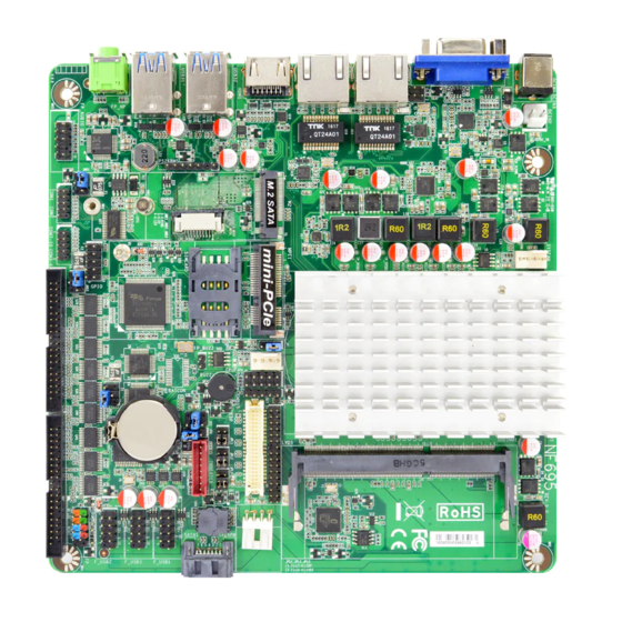
1-3 Layout Diagram Rear IO Panel Diagram: NF695HV Series: LAN1 RJ-45 HDMI1 LAN Port Port DCIN Port Line-out LAN2 RJ-45 USB 3.0 LAN Port Ports NF695L Series: LAN1 HDMI1 RJ-45 HDMI2 Port DCIN LAN Port Port Line-out USB 3.0 Ports Warning!! The board has a 12V DC-in power connector (DCIN3) in I/O back panel and an internal 12V power connector (DCIN2). - Page 10 Motherboard Internal Diagram NF695HV Series: Intel CPU Internal 12V DC-in Connector SYSFAN *LAN1_LED Header DDR3L Slot (SODIMM1) Full-size Mini-PCIE Slot (MPE1) M.2 Socket 3 Slot *Rear IO Connector (M2) (Refer to Page-4) LVDS CPUFAN SATA Power-out Connector *LAN2_LED Header SMBUS Header SATAIII Port *SIMCARD Slot Inverter...
- Page 11 NF695L Series: Intel CPU Internal 12V DC-in Connector SYSFAN DDR3L Slot *LAN1_LED Header (SODIMM1) Full-size Mini-PCIE Slot (MPE1) M.2 Socket 3 Slot *Rear IO LVDS Connector (M2) (Refer to Page-5) CPUFAN SATA Power-out Connector SMBUS Header SATAIII Port Inverter USB 2.0 Port FP_BUZZ GPIO Port Header...
- Page 12 Jumper Positions: ATX_AT JMD1 *JMD3 JMD2 *Note: the diagram above is from NF695HV series and serves as illustration purpose only. JMD3 is optional to NF695HV series models, please refer to the model you purchased for actual specifications.
- Page 13 Jumper Jumper Name Description JMD1 COM1 Serial Port Power Select 4-pin Block COM2 Serial Port Power Select 4-pin Block JMD2 *JMD3 COM3 Serial Port Power Select 4-pin Block (Optional) MPE1 Mini-PCIE Power 3VSB / 3.3V Select 3-Pin Block ATX Mode / AT Mode Select 3-Pin Block ATX_AT LVDS/EDP Inverter Power 3.3V/5V/12V Select...
- Page 14 SATAPW SATA Power Connector CPUFAN CPU Fan Connector SYSFAN System Fan Connector *Note: VGA/LAN2 is only optional for NF695HV series; HDMI2 is only optional for NF695L series. Headers Header Name Description Front Panel Header 9-pin Block (PWR LED/ HDD LED/ Power Button /Reset) F_USB1/ F_USB2/ USB 2.0 Header...
-
Page 15: Chapter 2 Hardware Installation
Chapter 2 Hardware Installation 2-1 Jumper Setting (1) JMD1 (4-pin): COM1 Port Pin9 Function Select JMD1 → COM1 Port Pin-9 2 4 6 2 4 6 JMD1 1 3 5 1 3 5 2-4 Closed: 4-6 Closed: 3-4 Closed: RING( Default); 12V. - Page 16 (3) JMD3 (4-pin): COM3 Header Pin9 Function Select JMD3 → COM3 Header Pin-9 JMD3 5 3 1 5 3 1 6 4 2 6 4 2 2-4 Closed: 3-4 Closed: 4-6 Closed: RING( Default); 12V. *Note: JMD3 is only optional for NF695HV series models with COM3 serial port header(from COM3-6 combo block).
- Page 17 (5) ATX_AT (3-pin): AT/ATX Mode Select ATX_AT → ATX/AT Mode Select 1-2 Closed: ATX Mode (Default); ATX_AT 2-3 Closed: AT Mode. *ATX Mode Selected: Press power button to power on after power input ready; AT Mode Selected: Directly power on as power input ready. (6) JP4 (3-pin): LVDS / EDP Inverter Backlight VCC 5V/12V Select JP4 →...
- Page 18 (7) JP3 (4-pin): LVDS / EDP Panel VCC 3.3V/5V/12V Select JP3 → LVDS Panel VCC 2-4 Closed: 3-4 Closed: 4-6 Closed: VCC=3.3V VCC= 5V; VCC= 12V. (Default); (8) JP2 (8-pin): Jumper Combo Block Pin 1&2 of JP2 (8-pin): Case Open Message Display Function Select 1-2 Open: 1-2 Closed: Normal (Default);...
- Page 19 Pin 3&4 of JP2 (8-pin): TXE Override Setting 3-4 Open: 3-4 Closed: Normal (Default); TXE Override. Pin 5&6 of JP2 (8-pin):Clear CMOS 5-6 Open: 5-6 Closed: Normal (Default); Clear CMOS. Pin 7&8 of JP2 (8-pin): Clear ME_RTC 7-8 Open: 7-8 Closed: Normal (Default);...
-
Page 20: Connectors And Headers
2-2 Connectors and Headers 2-2-1 Connectors (1) Rear I/O Connectors *Refer to Page-4. Icon Name Function 12V DC–in system power connector Power Jack For user to connect compatible power adapter to provide power supply for the system. HDMI Port To connect display device that support HDMI specification. - Page 21 (2) DCIN2 (2-pin): Internal 12V DC-in power connector Pin1 DCIN2 Pin No. Definition +12V DC_IN Warning!! The board has a 12V DC-in power jack (DCIN3) in I/O back panel and an internal 12V power connector (DCIN2). User can only connect one type of compatible power supply to one of them to power the system.
- Page 22 (4) SATAPW (4-pin) : SATA Power-out Connector Pin 1 SATAPW (5) CPUFAN (4-pin): CPU FAN Connector Pin1 +12V Fan Power Fan Speed Control CPUFAN (6) SYSFAN (4-pin): FAN Connector Pin1 +12V Fan Power SYSFAN Fan Speed Control...
-
Page 23: Headers
2-2-2 Headers *Notice: The following diagrams serves as illustration purpose only. Some of the headers are only optional. In the case of any differences please refer to the model you purchased for actual specifications. (1) FP (9-pin): Front Panel Header Pin 1 (2) F_USB1 / F_USB2 / F_USB3 (9-pin): USB 2.0 Port Header F_USB1... - Page 24 (3) COM1/COM2 (9-pin): Serial Port Header COM1 : RS232/422/485 Serial Port Header for NF695HV series; RS232 Serial Port Header for NF695L series; COM2 : RS232 Serial Port Header. Pin 1 *COM1 COM2 Pin NO. RS232 *RS422 *RS485 Pin 1 DATA- Pin 2 DATA+ Pin 3...
- Page 25 (4) COM3-6/COM7-10 (36-Pin): RS232 Serial Port Header (*Optional) Pin:B19 Pin:B1 *COM7-10 *COM3-6 Pin:A1 Pin:A20 COM7-10 Pin NO. RS232 Pin NO. RS232 COM3-6 Pin NO. RS232 Pin NO. RS232 Pin A1 DCD7 Pin B1 DSR7 Pin A1 DCD3 Pin B1 DSR3 COM3 Pin A2 SIN7...
- Page 26 (5) LAN1_LED/LAN2_LED (2-pin): LAN Activity LED Header LAN1_LED *LAN2_LED Pin1 *Note: LAN2_LED header is optional to NF695HV series only. (6) PS2KBMS (6-pin): PS/2 Keyboard & Mouse Header PS2KBMS Pin1 KB_DATA KB_CLK MS_CLK MS_DATA...
- Page 27 (7) FP_AUDIO (9-pin): Line-Out, MIC-In Header This header connects to Front Panel Line-out, MIC-In connector with cable. Pin 1 FP_AUDIO (8) GPIO (10-pin): GPIO Header GPIO Pin 1...
- Page 28 (9) SMBUS (5-pin): SMBUS Header SMBUS Pin1 DATA 3VSB (10) FP_BUZZ (2-pin): Buzzer Header Pin1 FP_BUZZ (11) INVERTER (8-pin): LVDS Inverter Connector Pin No. Definition Backlight Enable Pin 1 Backlight PWM INVERTER Back Light LED VCC Back Light LED VCC Backlight Up SW Backlight Down SW Warning! Find Pin-1 location of the inverter and make sure that the installation direction is correct!
- Page 29 (12) *EDP (40-Pin): EDP wafer Pin21 Pin1 Pin21 Pin40 Pin1 Pin20 Pin NO. Pin Define Pin NO. Pin Define Pin 1 Pin 21 Pin 2 Pin 22 Pin 3 EDP_TXN3 Pin 23 Pin 4 EDP_TXP3 Pin 24 Pin 5 Pin 25 Pin 6 EDP_TXN2 Pin 26...
- Page 30 (13) *LVDS (30-Pin): 24-bit dual channel LVDS Header LVDS Pin2 Pin 1 Pin NO. Pin Define Pin NO. Pin Define Pin 1 E-DATAN3 Pin 2 E-DATAP3 Pin 3 E-CLKN Pin 4 E-CLKP Pin 5 E-DATAN2 Pin 6 E-DATAP2 Pin 7 E-DATAN1 Pin 8 E-DATAP1...
-
Page 31: Chapter 3 Introducing Bios
Chapter 3 Introducing BIOS Notice! The BIOS options in this manual are for reference only. Different configurations may lead to difference in BIOS screen and BIOS screens in manuals are usually the first BIOS version when the board is released and may be different from your purchased motherboard. Users are welcome to download the latest BIOS version form our official website. -
Page 32: Bios Menu Screen
BIOS Menu Screen The following diagram show a general BIOS menu screen: Menu Bar General Help Items Current Setting Value Menu Items Function Keys Function Keys In the above BIOS Setup main menu of, you can see several options. We will explain these options step by step in the following pages of this chapter, but let us first see a short description of the function keys you may use here: l Press¨... -
Page 33: Getting Help
l Press <+>/<–> keys when you want to modify the BIOS parameters for the active option. l [F1]: General help. l [F2]: Previous value. l [F3]: Optimized defaults. l [F4]: Save & Exit. l Press <Esc> to quit the BIOS Setup. Getting Help Main Menu The on-line description of the highlighted setup function is displayed at the top right... -
Page 34: Main Menu
User can press the right or left arrow key on the keyboard to switch from menu bar. The selected one is highlighted. Main Menu Main menu screen includes some basic system information. Highlight the item and then use the <+> or <-> and numerical keyboard keys to select the value you want in each item. -
Page 35: Advanced Menu
3-7 Advanced Menu OS Selection The optional settings: [Windows]; [Intel Linux]; [MSDOS]. *Note: User need to go to this item to select the OS mode before installing corresponding OS driver, otherwise problems will occur when installing the driver. 4 Trusted Computing Press [Enter] to enable or disable ‘Security Device Support’. - Page 36 ACPI Sleep State Use this item to select the highest ACPI sleep state the system will enter when the suspend button is pressed. The optional settings are: [Suspend Disabled]; [S3 (Suspend to RAM)]. 4 Super I/O Configuration Press [Enter] to make settings for the following sub-items: Super IO Configuration ►...
- Page 37 Serial Port 2/3/4/5/6/7/8/9/10 Configuration Serial Port Use this item to enable or disable serial port (COM). The optional settings are: [Disabled]; [Enabled]. Change Settings Use this item to select an optimal setting for Super IO Device. The optional settings are: [Auto]; [IO=3F8h; IRQ=4]; [IO=2F8h; IRQ=3]; [IO=3E8h; IRQ=4];...
- Page 38 Case Open Detect Use this item to detect case has already open or not, show message in POST. The optional settings: [Disabled]; [Enabled]. When set as [Enabled], system will detect if COPEN has been short or not (refer to Page 16); if COPEN is short, system will show Case Open Message during POST. WatchDog Reset Timer Use this item to enable or disable WDT reset function.
- Page 39 4 Serial Port Console Redirection COM1 Console Redirection The optional settings: [Disabled]; [Enabled]. When set as [Enabled], the following sub-items shall appear: 4 Console Redirection Settings The settings specify how the host computer and the remote computer (which the user is using) will exchange data. Both computers should have the same or compatible settings.
- Page 40 The optional settings: [1]; [2]. Flow Control Flow control can prevent data loss from buffer overflow. When sending data, if the receiving buffers are full, a “stop” signal can be sent to stop the data flow. Once the buffers are empty, a “start” signal can be sent to re-start the flow. Hardware flow control uses two wires to send start/stop signals.
- Page 41 Serial Port for Out-of-Band Management/ Windows Emergency Management Services (EMS) Console Redirection The optional settings: [Disabled]; [Enabled]. When set as [Enabled], the following sub-items shall appear: 4 Console Redirection Settings The settings specify how the host computer and the remote computer (which the user is using) will exchange data.
- Page 42 Parity The default setting is: [None]. *This item may or may not show up, depending on different configuration. Stop Bits The default setting is: [1]. *This item may or may not show up, depending on different configuration. ► PC Health Status Press [Enter] to view current hardware health status, make further settings in ‘SmartFAN Configuration’.
- Page 43 4 CPU Configuration Press [Enter] to view current CPU configuration and make settings for the following sub-items: VT-d Use this item to enable or disable CPU VT-d. The optional settings: [Enabled]; [Disabled]. EIST Use this item to enable or disable Intel SpeedStep. The optional settings: [Disabled];...
- Page 44 option will not be created. PXE Boot Wait Time Use this item to set wait time to press [ESC] key to abort the PXE boot. Media Detect Count Use this item to set number of times presence of media will be checked. The optional settings range is from [1] to [50].
- Page 45 This function is supported when ‘ERP Support’ is set as [Disabled]. **Note: Wake-up System with Dynamic Time Use this item to enable or disable system wake on alarm event. System will wake on the current time + Increase minutes. The optional settings: [Disabled]; [Enabled]. When set as [Enabled], system will wake on the current time + increased minute(s).
- Page 46 Device Reset Time-out Use this item to set USB mass storage device start unit command time-out. The optional settings are: [10 sec]; [20 sec]; [30 sec]; [40 sec]. Device Power-up Delay Use this item to set maximum time the device will take before it properly reports itself to the host controller.
-
Page 47: Chipset Menu
3-8 Chipset Menu ► Uncore Configuration Press [Enter] to make settings for the following sub-items: GTT Size The optional settings are: [2MB]; [4MB]; [8MB]. DVMT Pre-Allocated Use this item to select DVMT 5.0 pre-allocated (fixed) graphics memory size used by the internal graphics device. The optional settings are: [64M];... - Page 48 Active LFP The optional settings are: [Disabled]; [LVDS]; [eDP]. * When set as [LVDS], user can make further setting in the following subitems: LCD Panel Type Use this item to select LCD panel used by Internal Graphics Device by selecting the appropriate setup item.
- Page 49 Memory Information The working memory information will be on display. ► South Cluster Configuration 4 PCI Express Configuration Press [Enter] to make settings for the following sub-items: PCI Express Configuration Peer Memory Write Enable The optional settings: [Disabled]; [Enabled]. Compliance Mode The optional settings: [Disabled];...
-
Page 50: Security Menu
HD-Audio Support Use this item to enable or disable HD-Audio Support. The optional settings are: [Disabled]; [Enabled]. System State after Power Failure Use this item to specify what state to go to when power re-applied after a power failure (G3 state). The optional settings are: [Always On];... - Page 51 administrator password. User Password If there is no password present on system, please press [Enter] to create new administrator password. If password is present on system, please press [Enter] to verify old password then to clear/change password. Press again to confirm the new administrator password.
- Page 52 [Disabled]. 4 Save all Secure Boot Variables This item will save NRRAM content of all Secure Boot variables to the files (WFI_SIGNATURE_LIST data format) in root folder on a target file system device. 4 Platform Key (PK)/Key Exchange Keys/Authorized Signature/Forbidden Signature/ Authorized TimeStamps/OS Recovery Signatures Use this item to enroll Factory Defaults or load the keys from a file with: 1.
-
Page 53: Boot Menu
3-10 Boot Menu Setup Prompt Timeout Use this item to set number of seconds to wait for setup activation key. Bootup Numlock State Use this item to select keyboard numlock state. The optional settings are: [On]; [Off]. Quiet Boot The optional settings are: [Disabled]; [Enabled]. Boot Option Priorities Boot Option #1/ Boot Option #2…... -
Page 54: Save & Exit Menu
3-11 Save & Exit Menu Save Changes and Reset This item allows user to reset the system after saving the changes. Discard Changes and Reset This item allows user to reset the system without saving any changes. Restore Defaults Use this item to restore /load default values for all the setup options. Save as User Defaults Use this item to save the changes done so far as user defaults. - Page 55 boot option selected. Lauch EFI Shell from filesystem device Use this item to launch EFI shell application (shell.efi) from one of the available filesystem device.