
Related Manuals for Supero SUPERSERVER 1026TT-TF


Summary of Contents for Supero SUPERSERVER 1026TT-TF
- Page 1 ® UPER 1026TT-TF UPER ERVER 1026TT-IBXF UPER ERVER 1026TT-IBQF UPER ERVER USER’S MANUAL Revision 1.0a...
- Page 2 The information in this User’s Manual has been carefully reviewed and is believed to be accurate. The vendor assumes no responsibility for any inaccuracies that may be contained in this document, makes no commitment to update or to keep current the information in this manual, or to notify any person or organization of the updates.
- Page 3 It provides information for the installation and use of the SuperServer 1026TT- TF/1026TT-IBXF/1026TT-IBQF. Installation and maintenance should be performed by experienced technicians only. The SuperServer 1026TT-TF/1026TT-IBXF/1026TT-IBQF is a 1U Twin (two server- boards in a 1U chassis) rackmount server based on the SC809TQ-1200B chassis and two Super X8DTT-F/X8DTT-IBXF/X8DTT-IBQFserverboards.
- Page 4 Chapter 4: System Safety You should thoroughly familiarize yourself with this chapter for a general overview of safety precautions that should be followed when installing and servicing the SuperServer 1026TT-TF/1026TT-IBXF/1026TT-IBQF. Chapter 5: Advanced Serverboard Setup Chapter 5 provides detailed information on the X8DTT-F/X8DTT-IBXF/X8DTT-IBQF serverboard, including the locations and functions of connectors, headers and jump- ers.
- Page 5 Preface Notes...
-
Page 6: Table Of Contents
UPER ERVER 1026TT-TF/1026TT-IBXF/1026TT-IBQF User's Manual Table of Contents Chapter 1 Introduction Overview ......................1-1 Serverboard Features ..................1-2 Processors ...................... 1-2 Memory ......................1-2 Serial ATA ......................1-2 PCI Expansion Slots ..................1-2 Ethernet Ports ....................1-2 Onboard Controllers/Ports ................1-3 Graphics Controller .................. - Page 7 Table of Contents Identifying the Sections of the Rack Rails ............2-4 Installing the Rack Rails ................. 2-5 Installing the Server into a Rack ..............2-6 Installing the Server into a Telco Rack ............2-7 Checking the Serverboard Setup ..............2-8 Preparing to Power On ...................
- Page 8 Jumper Settings .................... 5-18 5-11 Onboard Indicators ..................5-20 5-12 Installing Additional Drivers ................5-21 5-13 Confi guring Supero Doctor III ............... 5-22 Chapter 6 Advanced Chassis Setup Static-Sensitive Devices .................. 6-1 Precautions ..................... 6-1 Unpacking ....................... 6-1 Control Panel ....................6-2 System Fans ....................
-
Page 9: Chapter 1 Introduction
Chapter 1 Introduction Overview The SuperServer 1026TT-TF/1026TT-IBXF/1026TT-IBQF is a "1U Twin" server comprised of the SC809TQ-1200B 1U chassis and two (twin) X8DTT-F/X8DTT- IBXF/X8DTT-IBQF serverboards. Please refer to our web site for information on operating systems that have been certifi ed for use with the 1026TT-TF/1026TT- IBXF/1026TT-IBQF (www.supermicro.com). -
Page 10: Serverboard Features
UPER ERVER 1026TT-TF/1026TT-IBXF/1026TT-IBQF User's Manual Serverboard Features At the heart of the SuperServer 1026TT-TF/1026TT-IBXF/1026TT-IBQF lies two X8DTT-F/X8DTT-IBXF/X8DTT-IBQF dual processor serverboards, which are based on Intel's 5520 + ICH10R chipset. Below are the main features of the serverboards. Note that the features on each board are doubled for the server, which includes two nodes. -
Page 11: Onboard Controllers/Ports
Chapter 1: Introduction Onboard Controllers/Ports Onboard I/O backpanel ports on each serverboard include one COM port, a VGA port, two USB ports, a dedicated IPMI LAN port and two Gigabit LAN (NIC) ports. An Infi niBand port is also included on the X8DTT-IBXF/X8DTT-IBQF serverboards (the 1026TT-IBXF and 1026TT-IBQF only). - Page 12 UPER ERVER 1026TT-TF/1026TT-IBXF/1026TT-IBQF User's Manual CPU#1 CPU#2 Port1 Port0 Ports 2,1 Kawela MT25408 QSFP Ports Connect-X IB PCI-E Gen2/DDR or QDR Intel Ports RJ45 RJ45 5520 Ports PCI-E x16 7,8,9,10 SST25 VF016 CLINK CLINK ICH10R PE 4-1 SATA SATA #1 SATA #2 SATA #3 SATA #4...
-
Page 13: Server Chassis Features
Details on the chassis can be found in Chapter 6. System Power When confi gured as a SuperServer 1026TT-TF/1026TT-IBXF/1026TT-IBQF, the SC809TQ-1200B includes a single high-effi ciency (Gold Level) 1200W cold-swap power supply, which provides the power to both serverboards housed in the chas- sis. -
Page 14: Twin: System Notes
UPER ERVER 1026TT-TF/1026TT-IBXF/1026TT-IBQF User's Manual 1U Twin: System Notes As a 1U Twin confi guration, the 1026TT-TF/1026TT-IBXF/1026TT-IBQF is a unique server system. With two nodes incorporated into a single chassis, there are several points you should keep in mind. System Power A single power supply is used to provide the power for both serverboards. -
Page 15: Contacting Supermicro
Chapter 1: Introduction Contacting Supermicro Headquarters Address: Super Micro Computer, Inc. 980 Rock Ave. San Jose, CA 95131 U.S.A. Tel: +1 (408) 503-8000 Fax: +1 (408) 503-8008 Email: marketing@supermicro.com (General Information) support@supermicro.com (Technical Support) Web Site: www.supermicro.com Europe Address: Super Micro Computer B.V. Het Sterrenbeeld 28, 5215 ML 's-Hertogenbosch, The Netherlands Tel:... - Page 16 UPER ERVER 1026TT-TF/1026TT-IBXF/1026TT-IBQF User's Manual Notes...
-
Page 17: Chapter 2 Server Installation
Chapter 2: Server Installation Chapter 2 Server Installation Overview This chapter provides a quick setup checklist to get your server system up and running. Following these steps in the order given should enable you to have the system operational within a minimum amount of time. This quick setup assumes that your system has come to you with the processors and memory preinstalled. -
Page 18: Rack Precautions
UPER ERVER 1026TT-TF/1026TT-IBXF/1026TT-IBQF User's Manual • This product is for installation only in a Restricted Access Location (dedicated equipment rooms, service closets and the like). • This product is not suitable for use with visual display work place devices accord- ing to §2 of the the German Ordinance for Work with Visual Display Units. -
Page 19: Rack Mounting Considerations
Chapter 2: Server Installation • Always keep the rack's front door and all panels and components on the servers closed when not servicing to maintain proper cooling. • Make sure all power and data cables are properly connected and not blocking the chassis airfl... -
Page 20: Installing The Server Into A Rack
UPER ERVER 1026TT-TF/1026TT-IBXF/1026TT-IBQF User's Manual Installing the Server into a Rack This section provides information on installing the server into a rack unit with the rack rails provided. If the system has already been mounted into a rack, you can skip ahead to Sections 2-5 and 2-6. -
Page 21: Installing The Rack Rails
Chapter 2: Server Installation Installing the Rack Rails The SC809 chassis includes a set of inner rack rails in two sections: inner rails (A) and inner rail extensions (B). The inner rails are preattached and do not interfere with normal use of the chassis if you decide not to use a server rack. Attach the inner rail extensions to to the inner rails, to stabilize the chassis within the rack. -
Page 22: Installing The Server Into A Rack
UPER ERVER 1026TT-TF/1026TT-IBXF/1026TT-IBQF User's Manual Installing the Outer Rails to the Rack Attach the short bracket to the outside of the long bracket. You must align the pins with the slides. Also, both bracket ends must face the same direction. Adjust both the short and long brackets to the proper distance so that the rail fi... -
Page 23: Installing The Server Into A Telco Rack
Chapter 2: Server Installation Figure 2-4: Installing the Rack Rails Installing the Server into a Telco Rack To install the server into a Telco type rack, use two L-shaped brackets on either side of the chassis (four total). First, determine how far the server will extend out the front of the rack. -
Page 24: Checking The Serverboard Setup
UPER ERVER 1026TT-TF/1026TT-IBXF/1026TT-IBQF User's Manual Checking the Serverboard Setup After you install the server in the rack, you will need to open the top cover to make sure the serverboard is properly installed and all the connections have been made. Accessing the Inside of the System (Figure 2-5) To access the system, fi... -
Page 25: Preparing To Power On
Chapter 2: Server Installation Preparing to Power On Next, you should check to make sure the peripheral drives and the SATA drives and backplane have been properly installed and all connections have been made. Checking the SATA drives The SATA disk drives are accessable from the front of the server and can be installed and removed from the front of the chassis without removing the top chassis cover. - Page 26 UPER ERVER 1026TT-TF/1026TT-IBXF/1026TT-IBQF User's Manual Figure 2-5. Accessing the Inside of the System Remove these screws Remove this screw Remove this screw 2-10...
-
Page 27: Chapter 3 System Interface
Chapter 3: System Interface Chapter 3 System Interface Overview There are several LEDs on the two control panels and on the hard drive carriers to keep you constantly informed of the overall status of the system as well as the activ- ity and health of specifi... -
Page 28: Control Panel Leds
SUPERSERVER 1026TT-TF/1026TT-IBXF/1026TT-IBQF User's Manual Control Panel LEDs Each of the two control panels located on the front of the SC809 chassis has fi ve LEDs. Each LED provides you with critical information related its own specifi c serverboard. This section explains what each LED indicates when illuminated and any corrective action you may need to take. -
Page 29: Power
Chapter 3: System Interface Power Indicates power is being supplied to the system's power supply unit. This LED should normally be illuminated when the system is operating. Drive Carrier LEDs Each hard drive carrier has two LEDs. • Green: When illuminated, the green LED on the front of the drive carrier indi- cates drive activity. - Page 30 SUPERSERVER 1026TT-TF/1026TT-IBXF/1026TT-IBQF User's Manual Notes...
-
Page 31: Chapter 4 System Safety
System Safety Electrical Safety Precautions Basic electrical safety precautions should be followed to protect yourself from harm and the SuperServer 1026TT-TF/1026TT-IBXF/1026TT-IBQF from damage: • Be aware of the locations of the power on/off switch on the chassis as well as the room's emergency power-off switch, disconnection switch or electrical outlet. -
Page 32: General Safety Precautions
UPER ERVER 1026TT-TF/1026TT-IBXF/1026TT-IBQF User's Manual • Serverboard Battery: CAUTION - There is a danger of explosion if the onboard battery is installed upside down, which will reverse its polarites (see Figure 4-1). This battery must be replaced only with the same or an equivalent type recom- mended by the manufacturer (CR2032). -
Page 33: Esd Precautions
Chapter 4: System Safety • After accessing the inside of the system, close the system back up after ensuring that all connections have been made. ESD Precautions Electrostatic discharge (ESD) is generated by two objects with different electrical charges coming into contact with each other. An electrical discharge is created to neutralize this difference, which can damage electronic com ponents and printed circuit boards. -
Page 34: Operating Precautions
UPER ERVER 1026TT-TF/1026TT-IBXF/1026TT-IBQF User's Manual Operating Precautions Care must be taken to assure that the chassis cover is in place when the server is operating to assure proper cooling. Out of warranty damage to the system can occur if this practice is not strictly followed. Figure 4-1. -
Page 35: Chapter 5 Advanced Serverboard Setup
Chapter 5: Advanced Serverboard Setup Chapter 5 Advanced Serverboard Setup This chapter covers the steps required to install the X8DTT-F/X8DTT-IBXF/X8DTT- IBQF serverboard into the SC809TQ-1200B chassis, connect the data and power cables and install add-on cards. All serverboard jumpers and connections are also described. -
Page 36: Unpacking
UPER ERVER 1026TT-TF/1026TT-IBXF/1026TT-IBQF User's Manual Unpacking The serverboard is shipped in antistatic packaging to avoid electrostatic discharge. When unpacking the board, make sure the person handling it is static protected. Serverboard Installation This section explains the fi rst step of physically mounting the X8DTT-F/X8DTT-IBXF/ X8DTT-IBQF into the SC809TQ-1200B chassis. -
Page 37: Connecting Cables
Chapter 5: Advanced Serverboard Setup Warning: To avoid damaging the motherboard and its components, do not apply any force greater than 8 lbs. per square inch when installing a screw into a mount- ing hole. Connecting Cables Now that the serverboards are installed, the next step is to connect the cables to the boards. -
Page 38: I/O Ports
UPER ERVER 1026TT-TF/1026TT-IBXF/1026TT-IBQF User's Manual Figure 5-1. Control Panel Header Pins Ground x (Key) x (Key) Power On LED 3.3V HDD LED Front UID Button NIC1 LED (Link) NIC1 LED (Activity) NIC2 LED (Link) NIC2 LED (Activity) OH/Fan Fail/Pwr Fail/UID LED UID LED Power Fail LED 3.3V... -
Page 39: Processor And Heatsink Installation
Chapter 5: Advanced Serverboard Setup Processor and Heatsink Installation When handling the processor, avoid placing direct pressure on the label area of the fan. Also, do not place the serverboard on a conductive surface, which can damage the BIOS battery and prevent the system from booting up. - Page 40 UPER ERVER 1026TT-TF/1026TT-IBXF/1026TT-IBQF User's Manual After removing the plastic cap, use your thumb and the index fi nger to hold the CPU at the north and south center edges. Align the CPU key (the semi-circle cutout) with the socket key (the notch below the gold color dot on the side of the socket).
-
Page 41: Installing A Cpu Heatsink
Chapter 5: Advanced Serverboard Setup Installing a CPU Heatsink Remove power from the system and unplug the AC power cord from the power supply. Do not apply any thermal grease Screw #1 Screw #2 to the heatsink or the CPU die; the required amount has already been applied. -
Page 42: Removing The Heatsink
UPER ERVER 1026TT-TF/1026TT-IBXF/1026TT-IBQF User's Manual Removing the Heatsink Warning! We do not recommend that the CPU or the heatsink be removed. However, if you do need to uninstall the heatsink, please follow the instructions below to prevent damage to the CPU or the CPU socket. -
Page 43: Installing Memory
Chapter 5: Advanced Serverboard Setup Installing Memory CAUTION! Exercise extreme care when installing or removing DIMM modules to prevent any possible damage. Memory Support Each X8DTT-F/X8DTT-IBXF/X8DTT-IBQF has twelve 240-pin DIMM slots that can support up to 192 GB of ECC registered (or 48 GB of unbuffered) DDR3- 1333/1066/800 SDRAM. - Page 44 UPER ERVER 1026TT-TF/1026TT-IBXF/1026TT-IBQF User's Manual DIMM Population Table DIMM DIMMs DIMM Type (Reg.= Speeds (in MHz) Ranks per DIMM Slots per Populated Registered) (any combination; Channel per Channel SR=Single Rank, DR=Dual Rank, QR=Quad Rank) Reg. DDR3 ECC 800,1066,1333 SR, DR Reg.
-
Page 45: Adding Pci Cards
Chapter 5: Advanced Serverboard Setup Due to the memory allocation to system devices, the amount of memory that remains available for operational use will be reduced when 4 GB of RAM is used. The reduction in memory availability is disproportional. Refer to the table below. Possible System Memory Allocation &... -
Page 46: Serverboard Details
UPER ERVER 1026TT-TF/1026TT-IBXF/1026TT-IBQF User's Manual Serverboard Details Figure 5-4. X8DTT Series Motherboard Layout COM1 USB0/1 InfiniBand LAN2 LAN1 JNMI1 Connector JWD1 IPMI_LAN IPMB JPG1 JSPK1 Winbond InfiniBand WPCM450 Controller Controller JPL1 USB2/3 JWOL1 JLPC80 JBT1 Intel ICH10R Intel BIOS IOH-36D Battery T-SGPIO0 X8DTT Series... -
Page 47: X8Dtt-F/X8Dtt-Ibxf/X8Dtt-Ibqf Quick Reference
Chapter 5: Advanced Serverboard Setup X8DTT-F/X8DTT-IBXF/X8DTT-IBQF Quick Reference Jumper Description Default Setting JBT1 CMOS Clear (See Section 5-10) JPG1 VGA Enable/Disable Pins 1-2 (Enabled) JPL1 LAN1/2 Enable/Disable Pins 1-2 (Enabled) JWD1 Watch Dog Enable/Disable/Reset Pins 1-2 (Reset) Connector Description COM1 COM1 Serial Port FAN 1-4 System/CPU Fan Headers... -
Page 48: Connector Defi Nitions
UPER ERVER 1026TT-TF/1026TT-IBXF/1026TT-IBQF User's Manual Connector Defi nitions ATX Power 20-pin Connector Pin Defi nitions (ATX Power 1/2) Pin# Defi nition Pin # Defi nition ATX Power Connector PS On Ground The main ATX power supply connec- 5VSB Ground tors on the X8DTT-F/X8DTT-IBXF/ Ground Ground X8DTT-IBQF are proprietary 20-pin... - Page 49 Chapter 5: Advanced Serverboard Setup Overheat/Fan Fail/PWR Fail/UID OH/Fan Fail/ PWR Fail/Blue_UID LEDPin Defi nitions (JF1) Pin# Defi nition Pins 7 and 8 of JF1 are for the Over- Blue UID LED/5.5V.SB heat/Fan Fail/Power Fail and UID LED OH/Fan Fail/PWR Fail/Red UID connections.
- Page 50 UPER ERVER 1026TT-TF/1026TT-IBXF/1026TT-IBQF User's Manual Power On LED The Power On LED connector is lo- Power LED Pin Defi nitions (JF1) cated on pins 15 and 16 of JF1. This Pin# Defi nition connection is used to provide LED 5V Stby indication of power being supplied to Control the system.
- Page 51 Chapter 5: Advanced Serverboard Setup Serial Ports Serial Port Pin Defi nitions (COM) One serial port is included on the Pin # Defi nition Pin # Defi nition serverboard. The COM port is located beside the VGA port. See the table on the right for pin defi...
-
Page 52: 5-10 Jumper Settings
UPER ERVER 1026TT-TF/1026TT-IBXF/1026TT-IBQF User's Manual 5-10 Jumper Settings To modify the operation of the serverboard, jumpers can be used to choose between optional settings. Jumpers create shorts between two Connector pins to change the function of the Pins connector. Pin 1 is identifi ed with a square solder pad on the printed circuit board. - Page 53 Chapter 5: Advanced Serverboard Setup LAN1/LAN2 Enable/Disable LAN1/2 Enable/Disable Jumper Settings (JPL1) Change the setting of jumper JPL1 to Jumper Setting Defi nition enable or disable the LAN1 and LAN2 Pins 1-2 Enabled ports. See the table on the right for Pins 2-3 Disabled jumper settings.
-
Page 54: 5-11 Onboard Indicators
UPER ERVER 1026TT-TF/1026TT-IBXF/1026TT-IBQF User's Manual 5-11 Onboard Indicators LAN1/LAN2 LEDs (Connection Speed Indicator) LED Color Defi nition LAN1/LAN2 LEDs No connection or 10 Mb/s The Ethernet ports (located beside Green 100 Mb/s the COM port) have two LEDs. On Amber 1 Gb/s each Gb LAN port, one LED indicates activity when blinking while the other... -
Page 55: 5-12 Installing Additional Drivers
Chapter 5: Advanced Serverboard Setup 5-12 Installing Additional Drivers After you've installed the Windows Operating System, a screen as shown below will appear. You are now ready to install software programs and drivers that have not yet been installed. To install these software programs and drivers, click the icons to the right of these items. - Page 56 The Supero Doctor III program is a Web-based management tool that supports remote management capability. It includes Remote and Local Management tools. The local management is called the SD III Client. The Supero Doctor III program included on the CDROM that came with your motherboard allows you to monitor the environment and operations of your system.
- Page 57 Chapter 5: Advanced Serverboard Setup Note: SD III Software Revision 1.0 can be downloaded from our Web site at: ftp:// ftp.supermicro.com/utility/Supero_Doctor_III/. You can also download SDIII User's Guide at: http://www.supermicro.com/manuals/other/SDIII_User_Guide.pdf. For Linux, we will still recommend that you use Supero Doctor II. 5-23...
- Page 58 UPER ERVER 1026TT-TF/1026TT-IBXF/1026TT-IBQF User's Manual Notes 5-24...
-
Page 59: Chapter 6 Advanced Chassis Setup
Chapter 6: Advanced Chassis Setup Chapter 6 Advanced Chassis Setup This chapter covers the steps required to install components and perform mainte- nance on the SC809 chassis. For component installation, follow the steps in the order given to eliminate the most common problems encountered. If some steps are unnecessary, skip ahead to the step that follows. -
Page 60: Control Panel
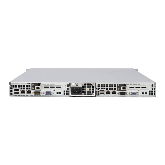
UPER ERVER 1026TT-TF/1026TT-IBXF/1026TT-IBQF User's Manual Figure 6-1. Chassis Front View Control Panel: Primary Serverboard Control Panel: Secondary Serverboard SATA Drives Figure 6-2. Chassis Rear View Dedicated IPMI Port PCI-Exp x16 Slot Dedicated IPMI Port PCI-Exp x16 Slot LAN Ports Power Supply LAN Ports USB Ports COM Port VGA Port UID Button USB Ports COM Port VGA Port... -
Page 61: System Fans
Chapter 6: Advanced Chassis Setup System Fans Each serverboard has its own set of three 4-cm high-performance PWM fans (for a total of six in the chassis) to provide the cooling for the system. Fan speed may be controlled by a setting in BIOS (see Chapter 7). System Fan Failure If a fan fails, the remaining fans will ramp up to full speed and the overheat/fan fail LED on the control panel will blink on and off. -
Page 62: Air Shrouds
UPER ERVER 1026TT-TF/1026TT-IBXF/1026TT-IBQF User's Manual Figure 6-3: Replacing a System Fan Air Shrouds Air shrouds concentrate airfl ow to maximize fan effi ciency. The SC809 chassis air shroud does not require screws to set up. Two identical air shrouds are needed in the system, one for each node. -
Page 63: Drive Bay Installation/Removal
Chapter 6: Advanced Chassis Setup Figure 6-4: Installing the Air Shrouds Drive Bay Installation/Removal Accessing the Drive Bays SATA Drives: Because of their hotswap capability, you do not need to access the inside of the chassis or power down the system to install or replace SATA drives. Proceed to the next step for instructions. - Page 64 UPER ERVER 1026TT-TF/1026TT-IBXF/1026TT-IBQF User's Manual SATA Drive Installation The SATA drives are mounted in drive carriers to simplify their installation and removal from the chassis. These carriers also help promote proper airfl ow for the system. For this reason, even empty carriers without drives installed must remain in the chassis.
-
Page 65: Power Supply
Chapter 6: Advanced Chassis Setup Figure 6-6. Removing a Drive Power Supply The 1026TT-TF/1026TT-IBXF/1026TT-IBQF has a single 1200 watt power supply. This power supply has the capability of operating at 100 - 240 input volts. Power Supply Failure If the power supply unit fails, the system will shut down and you will need to replace the power supply unit. - Page 66 UPER ERVER 1026TT-TF/1026TT-IBXF/1026TT-IBQF User's Manual Pull the power supply out using the handle provided. Push the new power supply module into the power bay until it clicks into place. Plug the AC power cord back into the module and power up the server by pushing the power on buttons for both nodes..
-
Page 67: Chapter 7 Bios
Chapter 7: BIOS Chapter 7 BIOS Introduction This chapter describes the AMI BIOS Setup Utility for the X8DTT/-F/-IBX/-IBXF/- IBQ/-IBQF. The AMI ROM BIOS is stored in a Flash EEPROM and can be easily updated. This chapter describes the basic navigation of the AMI BIOS Setup Utility setup screens. -
Page 68: Starting The Setup Utility
UPER ERVER 1026TT-TF/1026TT-IBXF/1026TT-IBQF User's Manual Starting the Setup Utility Normally, the only visible Power-On Self-Test (POST) routine is the memory test. As the memory is being tested, press the <Delete> key to enter the main menu of the AMI BIOS Setup Utility. From the main menu, you can access the other setup screens. - Page 69 Chapter 7: BIOS Supermicro X8DTT/-F/-IBX/-IBXF/-IBQ/-IBQF • BIOS Build Version : This item displays the BIOS revision used in your sys- tem. • BIOS Build Date : This item displays the date when this BIOS was completed. • AMI BIOS Core Version : This item displays the revision number of the AMI BIOS Core upon which your BIOS was built.
-
Page 70: Advanced Setup Confi Gurations
UPER ERVER 1026TT-TF/1026TT-IBXF/1026TT-IBQF User's Manual Advanced Setup Confi gurations Use the arrow keys to select Boot Setup and hit <Enter> to access the submenu items: BOOT Features Quick Boot If Enabled, this option will skip certain tests during POST to reduce the time needed for system boot. - Page 71 Chapter 7: BIOS Hit 'Del' Message Display This feature displays "Press DEL to run Setup" during POST. The options are Enabled and Disabled. Interrupt 19 Capture Interrupt 19 is the software interrupt that handles the boot disk function. When this item is set to Enabled, the ROM BIOS of the host adaptors will "capture"...
- Page 72 UPER ERVER 1026TT-TF/1026TT-IBXF/1026TT-IBQF User's Manual C1E Support Select Enabled to use the feature of Enhanced Halt State. C1E signifi cantly reduces the CPU's power consumption by reducing the CPU's clock cycle and voltage during a "Halt State." The options are Disabled and Enabled. Hardware Prefetcher (Available when supported by the CPU) If set to Enabled, the hardware pre fetcher will pre fetch streams of data and instruc- tions from the main memory to the L2 cache in the forward or backward manner to...
- Page 73 Chapter 7: BIOS tion and heat dissipation. Please refer to Intel’s web site for detailed information. The options are Disable (Disable GV3) and Enable (Enable GV3). Intel® TurboMode Technology Select Enabled to use the Turbo Mode to boost system performance. The options are Enabled and Disabled.
- Page 74 UPER ERVER 1026TT-TF/1026TT-IBXF/1026TT-IBQF User's Manual QPI L0s and L1 This enables the QPI power state to low power. L0s and L1 are automatically selected by the motherboard. The options are Disabled and Enabled. Memory Frequency This feature forces a DDR3 frequency slower than what the system has de- tected.
- Page 75 Chapter 7: BIOS Guardband Temperature (For the Closed Loop only) This is the temperature which applies to the DIMM temperature threshold. Each step is in 0.5 C increment. The default is [006]. Press "+" or "-" on your keyboard to change this value. Inlet Temperature This is the temperature detected at the chassis inlet.
- Page 76 UPER ERVER 1026TT-TF/1026TT-IBXF/1026TT-IBQF User's Manual Intel VT-d Select Enabled to enable Intel's Virtualization Technology support for Direct I/O VT-d by reporting the I/O device assignments to VMM through the DMAR ACPI Tables. This feature offers fully-protected I/O resource-sharing across the Intel platforms, providing the user with greater reliability, security and availability in networking and data-sharing.
- Page 77 Chapter 7: BIOS Hand-Off support. When enabled, the EHCI Interface will be changed from the BIOS- controlled to the OS-controlled. The options are Disabled and Enabled. IDE/SATA Confi guration When this submenu is selected, the AMI BIOS automatically detects the presence of the IDE devices and displays the following items: SATA#1 Confi...
- Page 78 UPER ERVER 1026TT-TF/1026TT-IBXF/1026TT-IBQF User's Manual is not used. Block Mode allows transfers of up to 64 KB per interrupt. Select Disabled to allow data to be transferred from and to the device one sector at a time. Select Auto to allow data transfer from and to the device occur multiple sectors at a time if the device supports it.
- Page 79 Chapter 7: BIOS Select UDMA0 to allow the BIOS to use Ultra DMA mode 0. It has a data transfer rate of 16.6 MBs. It has the same transfer rate as PIO mode 4 and Multi Word DMA mode 2. Select UDMA1 to allow the BIOS to use Ultra DMA mode 1.
- Page 80 UPER ERVER 1026TT-TF/1026TT-IBXF/1026TT-IBQF User's Manual PCI IDE BusMaster When enabled, the BIOS uses PCI bus mastering for reading/writing to IDE drives. The options are Disabled and Enabled. Load Onboard LAN1 Option ROM/Load Onboard LAN2 Option ROM Select Enabled to enable the onboard LAN1 or LAN2 Option ROM. This is to boot computer using a network interface.
- Page 81 Chapter 7: BIOS Redirection After BIOS POST Select Disabled to turn off Console Redirection after Power-On Self-Test (POST). Select Always to keep Console Redirection active all the time after POST. (Note: This setting may not be supported by some operating systems.) Select Boot Loader to keep Console Redirection active during POST and Boot Loader.
- Page 82 UPER ERVER 1026TT-TF/1026TT-IBXF/1026TT-IBQF User's Manual and system cooling. In both the alarms above, please take immediate action as shown below. (See the notes on P. 4-18 for more information.) CPU Temperature/System Temperature This feature displays current temperature readings for the CPU and the System. The following items will be displayed for your reference only: CPU Temperature The CPU thermal technology that reports absolute temperatures (Celsius/Fahr-...
- Page 83 Chapter 7: BIOS Notes: The system may shut down if it continues for a long period to prevent damage to the CPU. The information provided above is for your reference only. For more information on thermal management, please refer to Intel’s Web site at www.Intel.com.
- Page 84 UPER ERVER 1026TT-TF/1026TT-IBXF/1026TT-IBQF User's Manual Select to Enabled to allow USB devices to wakeup from S3/S4 state. The options are Enabled and Disabled. High Performance Event Timer Select Enabled to activate the High Performance Event Timer (HPET) that produces periodic interrupts at a much higher frequency than a Real-time Clock (RTC) does in synchronizing multimedia streams, providing smooth playback and reducing the de- pendency on other timestamp calculation devices, such as an x86 RDTSC Instruc- tion embedded in the CPU.
- Page 85 Chapter 7: BIOS • SEL Entry Number • SEL Record ID • SEL Record Type • Timestamp, Generator ID • Event Message Format User • Event Sensor Type • Event Sensor Number, • Event Dir Type • Event Data. Clear BMC System Event Log This feature is used to clear the BMC System Event Log.
- Page 86 UPER ERVER 1026TT-TF/1026TT-IBXF/1026TT-IBQF User's Manual Channel Number - Enter the channel number for the SET LAN Confi g com- mand. This is initially set to [1]. Press "+" or "-" on your keyboard to change the Channel Number. Channel Number Status - This feature returns the channel status for the Channel Number selected above: "Channel Number is OK"...
- Page 87 Chapter 7: BIOS Use this feature to select the parameter of your IP Address confi guration. IP Address The BIOS will automatically enter the IP address of this machine; however it may be over-ridden. IP addresses are 6 two-digit hexadecimal numbers (Base 16, 0 ~ 9, A, B, C, D, E, F) separated by dots.
- Page 88 UPER ERVER 1026TT-TF/1026TT-IBXF/1026TT-IBQF User's Manual Subnet Mask Confi guration Subnet masks tell the network which subnet this machine belongs to. The value of each three-digit number separated by dots should not exceed 255. Parameter Selector Use this feature to select the parameter of your Subnet Masks confi guration. Subnet Masks This item displays the current subnet masks setting for your IPMI connection.
- Page 89 Chapter 7: BIOS Specifi cation for more information at www.intel.com. The options are No Delay, 30 sec, 60 sec, 1.5 min, 2.0 min. Startup Delay - This feature enables or disables startup delay. The options are Enabled and Disabled. PEF Startup Delay - This sets the pre-determined time to delay PEF after system power-ups and resets.
-
Page 90: Security Settings
UPER ERVER 1026TT-TF/1026TT-IBXF/1026TT-IBQF User's Manual Security Settings The AMI BIOS provides a Supervisor and a User password. If you use both pass- words, the Supervisor password must be set fi rst. Supervisor Password This item indicates if a supervisor password has been entered for the system. Clear means such a password has not been used and Set means a supervisor password has been entered for the system. -
Page 91: Boot Confi Guration
Chapter 7: BIOS Clear User Password (Available only if User Password has been set) This item allows you to clear a user password after it has been entered. Password Check This item allows you to check a password after it has been entered. The options are Setup and Always. -
Page 92: Exit Options
UPER ERVER 1026TT-TF/1026TT-IBXF/1026TT-IBQF User's Manual Hard Disk Drives This feature allows the user to specify the boot sequence from all available hard disk drives. The settings are Disabled and a list of all hard disk drives that have been detected (i.e., 1st Drive, 2nd Drive, 3rd Drive, etc). •... - Page 93 Chapter 7: BIOS Save Changes and Exit When you have completed the system confi guration changes, select this option to leave the BIOS Setup Utility and reboot the computer, so the new system con- fi guration parameters can take effect. Select Save Changes and Exit from the Exit menu and press <Enter>.
- Page 94 UPER ERVER 1026TT-TF/1026TT-IBXF/1026TT-IBQF User's Manual Notes 7-28...
-
Page 95: Appendix A Bios Error Beep Codes
Appendix A: BIOS Error Beep Codes Appendix A BIOS Error Beep Codes During the POST (Power-On Self-Test) routines, which are performed each time the system is powered on, errors may occur. Non-fatal errors are those which, in most cases, allow the system to continue the boot-up process. - Page 96 UPER ERVER 1026TT-TF/1026TT-IBXF/1026TT-IBQF User's Manual Notes...
-
Page 97: Appendix B Installing Windows
Appendix B: Installing Windows Appendix B Installing Windows After all hardware components have been installed, you must fi rst confi gure Intel South Bridge RAID Settings before you install the Windows OS and other software drivers. To confi gure RAID settings, please refer to RAID Confi guration User Guides posted on our web site at www.supermicro.com/support/manuals. - Page 98 UPER ERVER 1026TT-TF/1026TT-IBXF/1026TT-IBQF User's Manual B-2 Installing Windows for a Non-RAID System Insert Microsoft's Windows XP/2003 Setup CD in the CD drive and the sys- tem will start booting up from CD. Continue with the OS installation. The Windows OS Setup screen will display. From the Windows XP/2003 Setup screen, press the <Enter>...
-
Page 99: Appendix C System Specifi Cations
Appendix C: System Specifi cations Appendix C System Specifi cations Processors Four Intel® 5500 Series processors in LGA1366 sockets Note: please refer to our website for details on supported processors. Chipset Intel 5520/ICH10R BIOS 32 Mb AMI SPI Flash ROM Memory Capacity Twelve DIMM sockets that can support up to 192 GB of ECC registered (or 48 GB of unbuffered) DDR3-1333/1066/800 SDRAM (384 or 96 GB for the system) - Page 100 UPER ERVER 1026TT-TF/1026TT-IBXF/1026TT-IBQF User's Manual Weight Gross Weight: 40 lbs. (18.2 kg.) System Cooling Six (6) high-performance 4-cm PWM (Pulse Width Modulated) fans System Input Requirements AC Input Voltage: 100 - 240V AC auto-range Rated Input Current: 13 - 4A max Rated Input Frequency: 50 to 60 Hz Power Supply Rated Output Power: 1200W (Part# PWS-1K21P-1R)
- Page 101 Appendix C: System Specifi cations Notes...
- Page 102 UPER ERVER 1026TT-TF/1026TT-IBXF/1026TT-IBQF User's Manual (continued from front) The products sold by Supermicro are not intended for and will not be used in life support systems, medical equipment, nuclear facilities or systems, aircraft, aircraft devices, aircraft/emergency com- munication devices or other critical systems whose failure to perform be reasonably expected to result in signifi...