Table of Contents
Advertisement
Quick Links
Advertisement
Table of Contents

Related Manuals for Supero 1028GQ-TR


Summary of Contents for Supero 1028GQ-TR
- Page 1 UPER ® UPER ERVER ® 1028GQ-TR 1028GQ-TRT USER’S MANUAL Revision 1.0...
- Page 2 The information in this User’s Manual has been carefully reviewed and is believed to be accurate. The vendor assumes no responsibility for any inaccuracies that may be contained in this document, makes no commitment to update or to keep current the information in this manual, or to notify any person or organization of the updates.
-
Page 3: About This Manual
About this Manual This manual is written for professional system integrators and PC technicians. It provides information for the installation and use of the SuperServer 1028GQ-TR(T). Installation and maintainance should be performed by experienced technicians only. Please refer to the server specifications page on our Web site for updates on supported memory, processors and operating systems (http://www.supermicro. -
Page 4: Table Of Contents
SUPERSERVER 1028GQ-TR(T) User's Manual Contents Chapter 1 Introduction ................1-1 Overview ......................1-1 Motherboard Features ..................1-2 Processors ...................... 1-2 Memory ......................1-2 Onboard Serial ATA ..................1-2 Input/Output Ports ................... 1-2 Graphics Controller ..................1-2 Chassis Features ................... 1-4 System Power ....................1-4 Hard Drives ..................... - Page 5 Preface Chapter 3 System Interface ..............3-1 Overview ......................3-1 Control Panel Buttons ..................3-2 Power ......................3-2 Unit Identification ..................... 3-2 Control Panel LEDs ..................3-2 NIC2 and NIC1 ....................3-2 Overheating ..................... 3-4 Overheat Temperature Setting ..............3-4 Responses ....................3-4 Drive Carrier LEDs ..................
- Page 6 SUPERSERVER 1028GQ-TR(T) User's Manual Input/Output Ports ................... 5-8 LAN Ports ......................5-8 Installing Memory .................... 5-9 Memory Support .................... 5-10 Processor and Memory Module Population Configuration ...... 5-10 Populating RDIM/LRDIMM DDR4 ECC Memory Modules ......5-11 Motherboard Details ..................5-12 Motherboard Quick Reference ..............5-13 Connector Definitions ..................
- Page 7 Preface Chapter 7 BIOS Introduction ...................... 7-1 Starting BIOS Setup Utility ................7-1 How To Change the Configuration Data ............7-1 Starting the Setup Utility ................. 7-2 Main Setup ...................... 7-2 Advanced Setup Configurations..............7-4 Event Logs ....................7-38 IPMI ....................... 7-40 Security ......................
- Page 8 SUPERSERVER 1028GQ-TR(T) User's Manual Notes...
-
Page 9: Chapter 1 Introduction
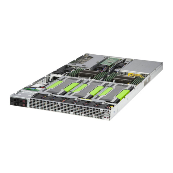
Chapter 1 Introduction Overview The SuperServer 1028GQ-TR(T) is a high-end GPU server comprised of two main subsystems: the SC118GQE-R2K03P 1U server chassis and the X10DGQ dual processor motherboard. It supports up to four GPUs, either actve or passive. Refer to the Supermicro web site for information on operating systems that have been certified for use with the system (www.supermicro.com). -
Page 10: Motherboard Features
ERVER 1028GQ-TR(T) User's Manual Motherboard Features At the heart of the SuperServer 1028GQ-TR(T) lies the X10DGQ, a dual processor motherboard based on the Intel PCH C612 chipset. Below are the main features of the motherboard. (See Figure 1-1 for a block diagram of the chipset.) -
Page 11: System Block Diagram
Chapter 1: Introduction VCCP0 12v VCCP1 12v #2-8 VR12.5 VR12.5 #2-7 #2-6 5 PHASE 5 PHASE #1-8 #2-5 #1-7 #2-4 145W 145W #1-6 #2-3 #2-2 #1-5 #1-4 #2-1 #1-3 #1-2 #1-1 CPU2 DDR4 DDR4 9.6G CPU1 9.6G PCI-E X16 G3 (LANE REVERSED IN RSC-G-6) PCI-E X16 G3 PCI-E X16 G3... -
Page 12: Chassis Features
UPER ERVER 1028GQ-TR(T) User's Manual Chassis Features The 1028GQ-TR(T) is built upon the SC118GQE-R2K03P chassis. The following are the main features. System Power The chassis features a redundant 2 KW power supply consisting of two hot-plug power modules. They have 80 Plus certification at Platinum Level (94%) high- efficiency. -
Page 13: Contacting Supermicro
Chapter 1: Introduction Contacting Supermicro Headquarters Address: Super Micro Computer, Inc. 980 Rock Ave. San Jose, CA 95131 U.S.A. Tel: +1 (408) 503-8000 Fax: +1 (408) 503-8008 Email: marketing@supermicro.com (General Information) support@supermicro.com (Technical Support) Web Site: www.supermicro.com Europe Address: Super Micro Computer B.V. Het Sterrenbeeld 28, 5215 ML 's-Hertogenbosch, The Netherlands Tel:... - Page 14 UPER ERVER 1028GQ-TR(T) User's Manual Notes...
-
Page 15: Chapter 2 Server Installation
Chapter 2: Server Installation Chapter 2 Server Installation Overview This chapter provides a quick setup checklist to get your system up and running. This quick setup assumes that your system has come to you with the processors and memory preinstalled. If your system is not already fully integrated with a serverboard, processors, system memory etc., please turn to the chapter or section noted in each step for details on installing specific components. -
Page 16: Warnings And Precautions
SUPERSERVER 1028GQ-TR(T) User's Manual Warnings and Precautions Rack Precautions • Ensure that the leveling jacks on the bottom of the rack are fully extended to the floor with the full weight of the rack resting on them. • In single rack installation, stabilizers should be attached to the rack. In multiple rack installations, the racks should be coupled together. -
Page 17: Rack Mounting Considerations
Chapter 2: Server Installation Rack Mounting Considerations Ambient Operating Temperature If installed in a closed or multi-unit rack assembly, the ambient operating temperature of the rack environment may be greater than the ambient temperature of the room. Therefore, consideration should be given to installing the equipment in an environment compatible with the manufacturer’s maximum rated ambient temperature (Tmra). -
Page 18: Installing The System Into A Rack
SUPERSERVER 1028GQ-TR(T) User's Manual Installing the System into a Rack There are a variety of rack units on the market, which may require a slightly different assembly procedure. This rail set fits a rack between 25.6" and 33" deep. The following is a basic guideline for installing the system into a rack with the rack mounting hardware provided. -
Page 19: Assembling The Outer Rails
Chapter 2: Server Installation Assembling the Outer Rails Each outer rail comes in two sections that must be assembled before mounting onto the rack. Assembling the Outer Rails 1. Identify the left and right outer rails by examining the ends, which bend outward. Match the left front outer rail with the left rear outer rail and the same for the right rails. -
Page 20: Installing The Outer Rails Onto The Rack
SUPERSERVER 1028GQ-TR(T) User's Manual Installing the Outer Rails onto the Rack Each end of the assembled outer rail includes a bracket with square pegs to fit into your rack holes. If you have an older rack with round holes, these brackets must be removed, and you must use screws to secure the rail to the rack. -
Page 21: Installing And Removing The Chassis From A Rack
Chapter 2: Server Installation Installing and Removing the Chassis From a Rack Installing the Chassis into a Rack 1. Align the rear of the chassis rails with the front of the rack rails and then push evenly on both sides of the chassis. The spring latch engages when the chassis is part way in. - Page 22 SUPERSERVER 1028GQ-TR(T) User's Manual Notes...
-
Page 23: Chapter 3 System Interface
Chapter 3: System Interface Chapter 3 System Interface Overview The server includes a control panel on the front that houses power buttons and status monitoring lights, status lights on the externally accessible hard drives, and status lights for the power supply visible from the back of the chassis Figure 3-1. -
Page 24: Control Panel Buttons
SuperServer 1028GQ-TR(T) User's Manual Control Panel Buttons The chassis includes two push-buttons that control power to the system. Power The main power switch is used to apply or remove power from the power supply to the server system. Turning off system power with this button removes the main power but keeps standby power supplied to the system. - Page 25 Chapter 3: System Interface Indicates activity on the hard drive when flashing. Information LED Alerts operator of several states, as noted in the table below. Information LED Status Description An overheat condition has occured. Continuously on and red (This may be caused by cable congestion.) Blinking red (1Hz) Fan failure, check for an inoperative fan.
-
Page 26: Overheating
SuperServer 1028GQ-TR(T) User's Manual Overheating There are several possible responses if the system overheats. Overheat Temperature Setting Some backplanes allow the overheat temperature to be set at 45, 50, or 55 by changing a jumper setting. For more information, consult the backplane user manual at www.supermicro.com. -
Page 27: Power Supply Leds
Chapter 3: System Interface Power Supply LEDs On the rear of the power supply module, an LED displays the status. • Solid Green: When illuminated, indicates that the power supply is on. • Solid Amber: When illuminated, indicates the power supply is plugged in and turned off, or the system is off but in an abnormal state. - Page 28 SuperServer 1028GQ-TR(T) User's Manual Notes...
-
Page 29: Chapter 4 Standardized Warning Statements For Ac Systems
Chapter 4: Warning Statements for AC Systems Chapter 4 Standardized Warning Statements for AC Systems About Standardized Warning Statements The following statements are industry standard warnings, provided to warn the user of situations which have the potential for bodily injury. Should you have questions or experience difficulty, contact Supermicro's Technical Support department for assistance. - Page 30 SUPERSERVER 1028GQ-TR(T) User's Manual Warnung WICHTIGE SICHERHEITSHINWEISE Dieses Warnsymbol bedeutet Gefahr. Sie befinden sich in einer Situation, die zu Verletzungen führen kann. Machen Sie sich vor der Arbeit mit Geräten mit den Gefahren elektrischer Schaltungen und den üblichen Verfahren zur Vorbeugung vor Unfällen vertraut.
- Page 31 Chapter 4: Warning Statements for AC Systems 안전을 위한 주의사항 경고! 이 경고 기호는 위험이 있음을 알려 줍니다. 작업자의 신체에 부상을 야기 할 수 있는 상태에 있게 됩니다. 모든 장비에 대한 작업을 수행하기 전에 전기회로와 관련된 위험요소들을 확인하시고 사전에 사고를 방지할 수 있도록 표준 작업절차를...
-
Page 32: Installation Instructions
SUPERSERVER 1028GQ-TR(T) User's Manual Installation Instructions Warning! Read the installation instructions before connecting the system to the power source. 設置手順書 システムを電源に接続する前に、 設置手順書をお読み下さい。 警告 将此系统连接电源前,请先阅读安装说明。 警告 將系統與電源連接前,請先閱讀安裝說明。 Warnung Vor dem Anschließen des Systems an die Stromquelle die Installationsanweisungen lesen. ¡Advertencia! Lea las instrucciones de instalación antes de conectar el sistema a la red de alimentación. -
Page 33: Circuit Breaker
Chapter 4: Warning Statements for AC Systems Circuit Breaker Warning! This product relies on the building's installation for short-circuit (overcurrent) protection. Ensure that the protective device is rated not greater than: 250 V, 20 A. サーキッ ト ・ ブレーカー この製品は、 短絡 (過電流) 保護装置がある建物での設置を前提としています。 保護装置の定格が250 V、... -
Page 34: Power Disconnection Warning
SUPERSERVER 1028GQ-TR(T) User's Manual 경고! 이 제품은 전원의 단락(과전류)방지에 대해서 전적으로 건물의 관련 설비에 의존합니다. 보호장치의 정격이 반드시 250V(볼트), 20A(암페어)를 초과하지 않도록 해야 합니다. Waarschuwing Dit product is afhankelijk van de kortsluitbeveiliging (overspanning) van uw electrische installatie. Controleer of het beveiligde aparaat niet groter gedimensioneerd is dan 220V, 20A. - Page 35 Chapter 4: Warning Statements for AC Systems ¡Advertencia! El sistema debe ser disconnected de todas las fuentes de energía y del cable eléctrico quitado de los módulos de fuente de alimentación antes de tener acceso el interior del chasis para instalar o para quitar componentes de sistema. Attention Le système doit être débranché...
-
Page 36: Equipment Installation
SUPERSERVER 1028GQ-TR(T) User's Manual Equipment Installation Warning! Only trained and qualified personnel should be allowed to install, replace, or service this equipment. 機器の設置 トレーニングを受け認定された人だけがこの装置の設置、 交換、 またはサービスを許可 されています。 警告 只有经过培训且具有资格的人员才能进行此设备的安装、更换和维修。 警告 只有經過受訓且具資格人員才可安裝、更換與維修此設備。 Warnung Das Installieren, Ersetzen oder Bedienen dieser Ausrüstung sollte nur geschultem, qualifiziertem Personal gestattet werden. -
Page 37: Restricted Area
Chapter 4: Warning Statements for AC Systems Waarschuwing Deze apparatuur mag alleen worden geïnstalleerd, vervangen of hersteld door geschoold en gekwalificeerd personeel. Restricted Area Warning! This unit is intended for installation in restricted access areas. A restricted access area can be accessed only through the use of a special tool, lock and key, or other means of security. -
Page 38: Battery Handling
SUPERSERVER 1028GQ-TR(T) User's Manual 경고! 이 장치는 접근이 제한된 구역에 설치하도록 되어있습니다. 특수도구, 잠금 장치 및 키, 또는 기타 보안 수단을 통해서만 접근 제한 구역에 들어갈 수 있습니다. Waarschuwing Dit apparaat is bedoeld voor installatie in gebieden met een beperkte toegang. - Page 39 Chapter 4: Warning Statements for AC Systems Warnung Bei Einsetzen einer falschen Batterie besteht Explosionsgefahr. Ersetzen Sie die Batterie nur durch den gleichen oder vom Hersteller empfohlenen Batterietyp. Entsorgen Sie die benutzten Batterien nach den Anweisungen des Herstellers. Attention Danger d'explosion si la pile n'est pas remplacée correctement. Ne la remplacer que par une pile de type semblable ou équivalent, recommandée par le fabricant.
-
Page 40: Redundant Power Supplies (If Applicable To Your System)
SUPERSERVER 1028GQ-TR(T) User's Manual Redundant Power Supplies (if applicable to your system) Warning! This unit might have more than one power supply connection. All connections must be removed to de-energize the unit. 冗長電源装置 このユニッ トは複数の電源装置が接続されている場合があります。 ユニッ トの電源を切るためには、 すべての接続を取り外さなければなりません。 警告 此部件连接的电源可能不止一个,必须将所有电源断开才能停止给该部件供电。... -
Page 41: Backplane Voltage (If Applicable To Your System)
Chapter 4: Warning Statements for AC Systems 경고! 이 장치에는 한 개 이상의 전원 공급 단자가 연결되어 있을 수 있습니다. 이 장치에 전원을 차단하기 위해서는 모든 연결 단자를 제거해야만 합니다. Waarschuwing Deze eenheid kan meer dan één stroomtoevoeraansluiting bevatten. Alle aansluitingen dienen verwijderd te worden om het apparaat stroomloos te maken. -
Page 42: Comply With Local And National Electrical Codes
SUPERSERVER 1028GQ-TR(T) User's Manual 경고! 시스템이 동작 중일 때 후면판 (Backplane)에는 위험한 전압이나 에너지가 발생 합니다. 서비스 작업 시 주의하십시오. Waarschuwing Een gevaarlijke spanning of energie is aanwezig op de backplane wanneer het systeem in gebruik is. Voorzichtigheid is geboden tijdens het onderhoud. -
Page 43: Product Disposal
Chapter 4: Warning Statements for AC Systems Attention L'équipement doit être installé conformément aux normes électriques nationales et locales. 경고! 현 지역 및 국가의 전기 규정에 따라 장비를 설치해야 합니다. Waarschuwing Bij installatie van de apparatuur moet worden voldaan aan de lokale en nationale elektriciteitsvoorschriften. -
Page 44: Hot Swap Fan Warning (If Applicable To Your System)
SUPERSERVER 1028GQ-TR(T) User's Manual ¡Advertencia! Al deshacerse por completo de este producto debe seguir todas las leyes y reglamentos nacionales. Attention La mise au rebut ou le recyclage de ce produit sont généralement soumis à des lois et/ou directives de respect de l'environnement. Renseignez-vous auprès de l'organisme compétent. - Page 45 Chapter 4: Warning Statements for AC Systems 警告 當您從機架移除風扇裝置,風扇可能仍在轉動。小心不要將手指、螺絲起子和其他 物品太靠近風扇。 Warnung Die Lüfter drehen sich u. U. noch, wenn die Lüfterbaugruppe aus dem Chassis genommen wird. Halten Sie Finger, Schraubendreher und andere Gegenstände von den Öffnungen des Lüftergehäuses entfernt. ¡Advertencia! Los ventiladores podran dar vuelta cuando usted quite ell montaje del ventilador del chasis.
-
Page 46: Power Cable And Ac Adapter
SUPERSERVER 1028GQ-TR(T) User's Manual Power Cable and AC Adapter Warning! When installing the product, use the provided or designated connection cables, power cables and AC adaptors. Using any other cables and adaptors could cause a malfunction or a fire. Electrical Appliance and Material Safety Law prohibits the use of UL or CSA -certified cables (that have UL/CSA shown on the code) for any other electrical devices than products designated by Supermicro only. - Page 47 Chapter 4: Warning Statements for AC Systems Attention Lors de l'installation du produit, utilisez les bables de connection fournis ou désigné. L'utilisation d'autres cables et adaptateurs peut provoquer un dysfonctionnement ou un incendie. Appareils électroménagers et de loi sur la sécurité Matériel interdit l'utilisation de UL ou CSA câbles certifiés qui ont UL ou CSA indiqué...
- Page 48 SUPERSERVER 1028GQ-TR(T) User's Manual Notes 4-20...
-
Page 49: Chapter 5 Advanced Motherboard Setup
Chapter 5: Advanced Serverboard Setup Chapter 5 Advanced Motherboard Setup This chapter covers the steps required to install processors and heatsinks to the X10DGQ motherboard, connect the data and power cables and install add-on cards. All motherboard jumpers and connections are described and a layout and quick reference chart are included in this chapter. -
Page 50: Installing The Processor And Heatsink
UPER ERVER 1028GQ-TR(T) User's Manual Installing the Processor and Heatsink Notes: • Always remove the power cord before adding, removing or changing a CPU. • When receiving a motherboard without a processor pre-installed, make sure that the plastic CPU socket cap is in place and none of the socket pins are bent;... - Page 51 Chapter 5: Advanced Serverboard Setup 3. W ith the sec ond lever f ully Open the load plate. retracted, gently push down on the "Open 1st" lever to loosen the load plate. Lift the load plate with your fingers to open it completely. 4.
- Page 52 UPER ERVER 1028GQ-TR(T) User's Manual Gently close the load plate. 7. With the "Close 1st" lever fully retracted, gently close the load plate. Push down and lock the lever labeled "Close 1st". 8. Make sure the locking mechanism on the "Close 1st" lever catches the lip of the load plate.
-
Page 53: Installing A Cpu Heatsink
Chapter 5: Advanced Serverboard Setup Installing a CPU Heatsink Figure 5-1. Heatsinks Installing a Heatsink 1. Place the heatsink on top of the CPU so that the four mounting holes are aligned with those on the retention mechanism. 2. Screw in two diagonal screws (#1 and #2) until just snug—do not over-tighten and damage the CPU. -
Page 54: Removing The Heatsink
UPER ERVER 1028GQ-TR(T) User's Manual Removing the Heatsink Caution: We do not recommend removing the CPU or the heatsink. If you do need to remove the heatsink, please follow the instructions below to prevent damage to the CPU or the CPU socket. -
Page 55: Connecting Cables
Chapter 5: Advanced Serverboard Setup Connecting Cables Now that the processors are installed, the next step is to connect the cables to the motherboard. These include the data (ribbon) cables for the peripherals and control panel and the power cables. Connecting Data Cables The cables used to transfer data from the peripheral devices have been carefully routed in preconfigured systems to prevent them from blocking the flow of cooling... -
Page 56: Superserver 1028Gq-Tr(T) User's Manual
Figure 5-2. Rear Panel I/O Ports 1. USB 3.0 Port 2. USB 3.0 Port 3. LAN 1 4. LAN 2 5. IPMI dedicated LAN 6. VGA (blue) LAN Ports The 1028GQ-TR model offers two Gigabit LAN ports; the 1028GQ-TRT model features two 10-Gigabit LAN ports. -
Page 57: Installing Memory
Chapter 5: Advanced Serverboard Setup Installing Memory For best performance, install memory modules of the same type and same speed in the slots as indicated in the tables on the following page. Note: Check the Supermicro web site for recommended memory modules. CAUTION Exercise extreme care when installing or removing DIMM modules to prevent any possible damage. -
Page 58: Memory Support
UPER ERVER 1028GQ-TR(T) User's Manual Memory Support The server features 16 DIMM slots that can support up to 1 TB of Load Reduction (LRDIMM) or up to 512 GB of Registered (RDIMM)/Non-volatile (NV-DIMM) ECC DDR4-2133/1866/1600 MHz memory. Memory speed support depends on the processors installed in the system. -
Page 59: Populating Rdim/Lrdimm Ddr4 Ecc Memory Modules
Chapter 5: Advanced Serverboard Setup Populating RDIM/LRDIMM DDR4 ECC Memory Modules Speed (MT/s), Slot per Channel (SPC) & DIMM per Channel (DPC) 5-11... -
Page 60: Motherboard Details
UPER ERVER 1028GQ-TR(T) User's Manual Motherboard Details BIOS JSLOT6 JPME2 BIOS LICENSE JBT1 JPW1 JPW2 JPW4 JPW5 X10DGQ Rev. 1.00 CPU2 CPU1 FAN_PWR1 JPW3 IPMI CODE BATTERY BAR CODE JITP1 FAN5 JPW6 Figure 5-4. X10DGQ Layout Notes • " " indicates the location of "Pin 1". -
Page 61: Motherboard Quick Reference
Chapter 5: Advanced Serverboard Setup Motherboard Quick Reference Jumpers Jumper Description Default Setting JBT1 Clear CMOS/Reset BIOS See Chapter 2 Configuration JPB1 BMC Enable Pins 1-2 (Enabled) JPG1 VGA Enable Pins 1-2 (Enabled) JPME2 Manufacture Mode (ME) Pins 1-2 (Normal) Select JWD1 Watch Dog... -
Page 62: Connector Definitions
UPER ERVER 1028GQ-TR(T) User's Manual Connector Definitions Power Connectors Two 50-pin proprietary power connectors (JPW1/JPW2) are used to provide main power to your system. Four 8-pin power connectors, located at JPW3/JPW4/JPW5/ JPW6, provide power to PCI-E expansion cards. In addition, two 4-pin power con- nectors (HDD_PWR1/HDD_PWR2) are used for onboard HDDs, while another 4-pin power connector (FAN_PWR1) powers the fan board AOM-QG-FAN. - Page 63 Chapter 5: Advanced Serverboard Setup NMI Button NMI Button Pin Definitions (JF1) The non-maskable interrupt button Pin# Definition header is located on pins 19 and 20 Control of JF1. Refer to the table on the right Ground for pin definitions. Power LED Power LED Pin Definitions (JF1)
- Page 64 UPER ERVER 1028GQ-TR(T) User's Manual Overheat (OH)/Fan Fail/PWR Fail/ OH/Fan Fail/ PWR Fail/Blue_ UID LED UID LED Pin Definitions (JF1) Pin# Definition Connect an LED cable to pins 7 and 8 of Front Control Panel to use the Blue_UID LED...
-
Page 65: Other Connectors
Chapter 5: Advanced Serverboard Setup Other Connectors Fan Headers 4-Pin Fan Header Pin Definitions The 4-pin fan headers are backward Pin# Definition compatible with traditional 3-pin fans, Ground however fan speed control is available +12V for 4-pin fans only. The fan speeds are Tachometer controlled by IPMI. -
Page 66: Chassis Intrusion
UPER ERVER 1028GQ-TR(T) User's Manual Standby Power Header Standby PWR Pin Definitions The onboard standby power header Pin# Definition is located at JSTBY1 on the mother- +5V Standby board. See the table on the right for Ground pin definitions. (You must also have a... - Page 67 Chapter 5: Advanced Serverboard Setup SIO Slot JSLOT6 is the slot for the rear I/O add-on module. PCI Slot CPU0/CPU1 SLOT5 PCIE 3.0 x8/x8 is the slot for the riser card (RSC-GR-A88) that enables two low-profile PCIe expansion cards. GPU Slots The slots for the GPU riser cards are: •...
-
Page 68: Jumper Settings
UPER ERVER 1028GQ-TR(T) User's Manual Jumper Settings Explanation of Jumpers To modify the operation of the motherboard, jumpers can be used Connector to choose between optional settings. Pins Jumpers create shorts between two pins to change the function of the Jumper connector. - Page 69 Chapter 5: Advanced Serverboard Setup VGA Enable/Disable VGA Enable/Disable Jumper Settings JPG1 allows you to enable or disable Jumper Setting Definition the onboard VGA port. The default Pins 1-2 Enabled position is on pins 1 and 2 to enable Pins 2-3 Disabled VGA.
-
Page 70: Onboard Indicators
UPER ERVER 1028GQ-TR(T) User's Manual Onboard Indicators LAN 1/2 LAN1/2 Port LEDs Link LED Activity LED The Ethernet ports on the rear I/O panel have two indicators. On each LAN Link Indicator port, the LED on the right indicates LED Settings activity by blinking amber. -
Page 71: 5-10 Sata Ports
Chapter 5: Advanced Serverboard Setup 5-10 SATA Ports Six Serial ATA ports (SATA1-SATA6), supported by the Intel PCH, are located on the motherboard. SATA5/6, colored in yellow, are used with Supermicro SuperDOM (Disk-on-Module) connectors with power pins built in. Supermicro SuperDOM connectors are backward-compatible with regular SATA HDDs and SATA DOMs that require power cables. -
Page 72: 5-11 Installing Software
UPER ERVER 1028GQ-TR(T) User's Manual 5-11 Installing Software The Supermicro ftp site contains drivers and utilities for your system at ftp://ftp. supermicro.com. Some of these must be installed, such as the chipset driver. After accessing the ftp site, go into the CDR_Images directory and locate the ISO file for your motherboard. -
Page 73: Superdoctor ® 5
Chapter 5: Advanced Serverboard Setup SuperDoctor ® The Supermicro SuperDoctor 5 is a hardware and operating system services moni- toring program that functions in a command-line or web-based interface in Windows and Linux operating systems. The program monitors system health information such as CPU temperature, system voltages, system power consumption, fan speed, and provides alerts via email or Simple Network Management Protocol (SNMP). -
Page 74: 5-12 Onboard Battery
UPER ERVER 1028GQ-TR(T) User's Manual Figure 5-8. SuperDoctor 5 Interface Display Screen (Remote Control) Note: The SuperDoctor 5 program and User’s Manual can be downloaded from the Supermicro web site at http://www.supermicro.com/products/nfo/sms_sd5.cfm. For Linux, we recommend that you use the SuperDoctor II application instead. -
Page 75: Chapter 6 Advanced Chassis Setup
Chapter 6: Advanced Chassis Setup Chapter 6 Advanced Chassis Setup This chapter covers the steps required to install components and perform maintenance on the SC118GQE-RK03 chassis. The only tool required is a Phillips screwdriver. Review the warnings and precautions before setting up or servicing components. These include information in Chapter 4: Warning Statements for AC Systems. -
Page 76: Static-Sensitive Devices
UPER ERVER 1028GQ-TR(T) User's Manual Static-Sensitive Devices Electrostatic Discharge (ESD) can damage electronic com ponents. To prevent damage to any printed circuit boards (PCBs), it is important to handle them very carefully. The following measures are generally sufficient to protect your equipment from ESD damage. -
Page 77: Removing The Chassis Cover
Chapter 6: Advanced Chassis Setup Removing the Chassis Cover The SC118GQE has a two piece cover. For either the front cover or the rear cover: 1. Unscrew the two thumb screws on the end of the chassis. 2. Remove the screw securing the cover to each side of the chassis. 3. -
Page 78: Control Panel
UPER ERVER 1028GQ-TR(T) User's Manual Control Panel The control panel, located on the front of the chassis, must be connected to the JF1 connector on the serverboard to provide you with system status indicators. These wires have been bundled together as a ribbon cable to simplify the connection. -
Page 79: Externally Accessable Drives
Chapter 6: Advanced Chassis Setup Externally Accessable Drives The two hot-swap drives are mounted in drive carriers to simplify their installation and removal from the chassis. System power may remain on when removing carriers with drives installed. These carriers also help promote proper airflow for the drive bays. - Page 80 UPER ERVER 1028GQ-TR(T) User's Manual Dummy Drive Drive Carrier Figure 6-5. Removing a Dummy Drive from Carrier Installing a Drive into the Carrier 1. Remove the dummy drive from the carrier by removing four screws. 2. Install a new drive into the carrier with the printed circuit board side facing down so that the mounting holes in the drive align with those in the carrier.
- Page 81 Chapter 6: Advanced Chassis Setup 3. Secure the hard drive into the carrier with the screws. 4. Open the drive carrier handle and use it push the carrier assembly into the chassis. 5. Gently close the drive carrier handle to secure the drive and carrier into the chassis drive bay.
-
Page 82: Internal Drives
UPER ERVER 1028GQ-TR(T) User's Manual Internal Drives The system supports one or two 2.5" fixed hard disk drives, using the included mounting bracket. Internal HDDs Figure 6-7. Internal HDD Position Installing Internal Drives 1. Mount the drives in the bracket, securing them with screws. -
Page 83: Adding Expansion Cards
Chapter 6: Advanced Chassis Setup Adding Expansion Cards The system supports up to four graphic processor units (GPUs) and two low-profile PCIe expansion cards. Graphic Processor Units Figure 6-8. Front GPUs Installing the Front GPUs Installing the front GPUs requires riser cards, RSC-G-6. 1. - Page 84 UPER ERVER 1028GQ-TR(T) User's Manual Figure 6-9. Rear GPU Installing the rear GPU uses the riser card, RSC-GR-6. Installing the Rear GPU 1. Remove the chassis bracket. 2. Attach the riser card to the bracket. 3. Insert the GPU into the riser card slot.
- Page 85 Chapter 6: Advanced Chassis Setup Cable Reference Cable Set Part Number Description Quantity/ (GPU, connector type, length) Server K80/M60 CBL-PWEX-0782 GPU1 8pin 55cm CBL-PWEX-0783 GPU2+3 8pin 39cm CBL-PWEX-0814 GPU4 8pin 11cm CBL-PWEX-0784 GPU1 6+2pin 55cm CBL-PWEX-0785 GPU2+3 6+2pin 39cm CBL-PWEX-0786 GPU4 6+2pin 11cm...
-
Page 86: Pci
UPER ERVER 1028GQ-TR(T) User's Manual A riser card on chassis bracket allows you to add one or two low-profile PCI expansion cards. All expansion cards are PCI-Express 3.0. Installation requires the riser card RSC-GR-6. Figure 6-10. PCI Expansion Cards Installing the Rear PCI Expansion Cards 1. -
Page 87: Cooling
Chapter 6: Advanced Chassis Setup Cooling System Fans The standard chassis contains nine 4-cm counter-rotating, high-performance fans. Two more expansion card fans are available. Fan speed is controlled by system temperature via IPMI. If a fan fails, the remaining fan will ramp up to full speed and the overheat/fan fail LED on the control panel will turn on. -
Page 88: Air Shroud And Block
UPER ERVER 1028GQ-TR(T) User's Manual 4. Place the new fan into the vacant space in the housing while making sure the arrows on the top of the fan (indicating air direction) point in the same direction as the arrows on the other fans. -
Page 89: Power Supply
Chapter 6: Advanced Chassis Setup Power Supply The 1028GQ-TR(T) has a 2000 watt redundant hot-plug power supply consisting of two power modules. Each power supply module has an auto-switching capability, which enables it to automatically sense and operate at a 100V - 240V input voltage. - Page 90 UPER ERVER 1028GQ-TR(T) User's Manual Notes 6-16...
-
Page 91: Chapter 7 Bios
Chapter 7: AMI BIOS Chapter 7 BIOS Introduction This chapter describes the AMI BIOS setup utility for the X10DGQ. It also provides the instructions on how to navigate the AMI BIOS setup utility screens. The AMI ROM BIOS is stored in a Flash EEPROM and can be easily updated. Starting BIOS Setup Utility To enter the AMI BIOS setup utility screens, press the <Del>... -
Page 92: Starting The Setup Utility
SuperServer 1028GQ-TR(T) User’s Manual Starting the Setup Utility Normally, the only visible Power-On Self-Test (POST) routine is the memory test. As the memory is being tested, press the <Delete> key to enter the main menu of the AMI BIOS setup utility. From the main menu, you can access the other setup screens. - Page 93 Chapter 7: AMI BIOS The AMI BIOS Main menu displays the following information: System Date/System Time Use this item to change the system date and time using the arrow keys. Enter new values through the keyboard and press <Enter>. Press the <Tab> key to move between fields.
-
Page 94: Advanced Setup Configurations
SuperServer 1028GQ-TR(T) User’s Manual Advanced Setup Configurations Select the Advanced tab to access the following submenu items. Boot Features Boot Configuration Quiet Boot Use this item to select bootup screen display between POST messages and the OEM logo. Select Disabled to display the POST messages. Select Enabled to display the OEM logo instead of the normal POST messages. -
Page 95: Power Configuration
Chapter 7: AMI BIOS ROM display set by the system BIOS. The options are Force BIOS and Keep Current. Bootup Num-Lock Use this item to set the power-on state for the Numlock key. The options are Off and On. Wait For 'F1' If Error Select Enabled to force the system to wait until the 'F1' key is pressed when an error occurs. -
Page 96: Cpu Configuration
SuperServer 1028GQ-TR(T) User’s Manual CPU Configuration This submenu displays the following CPU information as detected by the BIOS. It also allows the user to configure CPU settings. Processor 0/Processor 1 This submenu displays the following information of the CPU installed in Socket 0, and Socket 1. - Page 97 Chapter 7: AMI BIOS The options are Enable and Disable. (Refer to Intel and Microsoft websites for more information.) PPIN Control Select Unlock/Enable to use the Protected-Processor Inventory Number (PPIN) in the system. The options are Unlock/Enable and Unlock/Disable. Hardware Prefetcher (Available when supported by the CPU) If set to Enable, the hardware prefetcher will prefetch streams of data and instructions from the main memory to the L2 cache to improve CPU performance.
-
Page 98: Advanced Power Management Configuration
SuperServer 1028GQ-TR(T) User’s Manual AES-NI Select Enable to use the Intel Advanced Encryption Standard (AES) New Instructions (NI) to ensure data security. The options are Enable and Disable. Intel Virtualization Technology (Available when supported by the CPU) Select Enable to support Intel Virtualization Technology, which will allow one platform to run multiple operating systems and applications in independent partitions, creating multiple "virtual"... - Page 99 Chapter 7: AMI BIOS CPU P State Control (Available when Power Technology is set to Custom) EIST (P-states) EIST (Enhanced Intel SpeedStep Technology) allows the system to automatically adjust processor voltage and core frequency to reduce power consumption and heat dissipation.
-
Page 100: Chipset Configuration
SuperServer 1028GQ-TR(T) User’s Manual CPU T State Control (Available when Power Technology is set to Custom) ACPI (Advanced Configuration Power Interface) T-States If this item is set to Enable, CPU throttling will be supported by the operating system to reduce power consumption. The options are Disable and Enable. - Page 101 Chapter 7: AMI BIOS No PCIe Port Active ECO Use this feature to select a workaround setting to implement the engineering- change order (ECO) on the system when the PCI ports specified by the user are not active. The options are PCU Squelch exit ignore option and Reset the SQ FLOP by CSR option.
- Page 102 SuperServer 1028GQ-TR(T) User’s Manual Non-Fatal Err (Error) Over Select Enable to force non-fatal error prorogation to the IIO core error logic for the port specified by the user. The options are Disable and Enable. Corr Err (Correctable Error) Over Select Enable to force correctable error prorogation to the IIO core error logic for the port specified by the user.
- Page 103 Chapter 7: AMI BIOS PCI-E Port L0s Exit Latency Use this feature to set the length of time required for the port specified by the user to complete the transition from L0s to L0. The default setting is 4uS - 8uS. PCI-E Port L1 Exit Latency Use this feature to set the length of time required for the port specified by the user to complete the transition from L1 to L0.
- Page 104 SuperServer 1028GQ-TR(T) User’s Manual Gen3 (Generation 3) DN TX Preset Use this item to set the Preset mode for PCI-E Gen3 downstream transactions (from the master device to a slave device). The options are Auto, P0 (-6.0/0.0 dB), P1 (-3.5/0.0 dB), P2 (-4.5/0.0 dB), P3 (-2.5/0.0 dB), P4 (0.0/0.0 dB), P5 (0.0/2.0 dB), P6 (0.0/2.5 dB), P7 (-6.0 /3.5 dB), P8 (-3.5/3.5 dB), and P9 (0.0/3.5...
- Page 105 Chapter 7: AMI BIOS IOU1 (IIO PCIE Port 3) This feature allows the user to set the bus speed between the IOU1 and the PCI-Exp port specified above. The options are x4x4x4x4, x4x4x8, x8x4x4, x8x8, x16, and Auto. No PCIe Port Active ECO Use this feature to select a workaround setting to implement the engineering- change order (ECO) on the system when the PCI ports specified by the user are not active.
- Page 106 SuperServer 1028GQ-TR(T) User’s Manual PCI-E Port L0s Exit Latency Use this feature to set the length of time required for the port specified by the user to complete the transition from L0s to L0. The default setting is 4uS - 8uS.
-
Page 107: Ioat Configuration
Chapter 7: AMI BIOS Gen3 (Generation 3) DN TX Preset Use this item to set the Preset mode for PCI-E Gen3 downstream transactions (from the master device to a slave device). The options are Auto, P0 (-6.0/0.0 dB), P1 (-3.5/0.0 dB), P2 (-4.5/0.0 dB), P3 (-2.5/0.0 dB), P4 (0.0/0.0 dB), P5 (0.0/2.0 dB), P6 (0.0/2.5 dB), P7 (-6.0 /3.5 dB), P8 (-3.5/3.5 dB), and P9 (0.0/3.5 dB). - Page 108 SuperServer 1028GQ-TR(T) User’s Manual No Snoop Select Enable to support no-snoop mode for each CB device. The options are Disable and Enable. Relaxed Ordering Select Enable for relaxed ordering support, which will allow certain transactions to be processed and completed prior to other transactions that have already been queued and that violate the strict ordering rules of PCI processing.
-
Page 109: Memory Configuration
Chapter 7: AMI BIOS Link L0p Enable Select Enable for Link L0p support. The options are Disable and Enable. Link L1 Enable Select Enable for Link L1 support. The options are Disable and Enable. Early Snoop Select Enable to support Early Snoop mode for the QPI link. The options are Disable, Enable, and Auto. -
Page 110: Dimm Information
SuperServer 1028GQ-TR(T) User’s Manual Set Throttling Mode Throttling improves reliability and reduces power consumption in processors via automatic voltage control during processor idle states. The options are Disabled and CLTT (Closed Loop Thermal Throttling). Socket Interleave Below 4GB Select Enabled for the memory above the 4G Address space to be split between two sockets. -
Page 111: South Bridge Configuration
Chapter 7: AMI BIOS memory behind the PCH will be scrubbed every day. The options are Disable and Enable. Patrol Scrub Interval This feature allows you to decide how many hours the system should wait before the next complete patrol scrub is performed. Use the keyboard to enter a value from 0-24. -
Page 112: Sata Configuration
SuperServer 1028GQ-TR(T) User’s Manual EHCI Hand-Off This item is for operating systems that do not support Enhanced Host Controller Interface (EHCI) hand-off. When this item is enabled, EHCI ownership change will be claimed by the EHCI driver. The settings are Disabled and Enabled. - Page 113 Chapter 7: AMI BIOS SATA Port 0-Port 5 This item displays the information detected on the installed SATA drive on the particular SATA port. • Model number of drive and capacity • Software Preserve Support SATA Port 0-Port 5 Select Enabled to enable a SATA port specified by the user. The options are Disabled and Enabled.
- Page 114 SuperServer 1028GQ-TR(T) User’s Manual the I/O is inactive for an extended period of time, and the power state will return to normal when the I/O becomes active. The options are Disabled and Enabled. SATA RAID Option ROM/UEFI Driver Select EFI to load the EFI driver for system boot. Select Legacy to load a legacy driver for system boot.
- Page 115 Chapter 7: AMI BIOS sSATA Configuration When this submenu is selected, AMI BIOS automatically detects the presence of the SATA devices that are supported by the PCH-sSATA controller and displays the following items: sSATA Controller This item enables or disables the onboard SATA controller supported by the Intel PCH-sSATA controller.
- Page 116 SuperServer 1028GQ-TR(T) User’s Manual sSATA Port 0-Port 3 sSATA Device Type Use this item to specify if the sSATA port specified by the user should be connected to a Solid State drive or a Hard Disk Drive. The options are Hard Disk Drive and Solid State Drive.
- Page 117 Chapter 7: AMI BIOS sSATA Port 0-Port 3 Select Enabled to enable an sSATA port specified by the user. The options are Disabled and Enabled. sSATA Port 0-Port 3 Hot Plug This feature designates this port for hot plugging. Set this item to Enabled for hot-plugging support, which will allow the user to replace an sSATA drive without shutting down the system.
- Page 118 SuperServer 1028GQ-TR(T) User’s Manual PCIe/PCI/PnP Configuration The following PCI information will be displayed: PCI Latency Timer Use this item to configure the PCI latency timer for a device installed on a PCI bus. Select 32 to set the PCI latency timer to 32 PCI clock cycles. The options are 32, 64, 96, 128, 160, 192, 224, and 248 (PCI Bus Clocks).
- Page 119 Chapter 7: AMI BIOS ASPM Support Use this item to set the Active State Power Management (ASPM) level for a PCI-E device. Select Auto for the system BIOS to automatically set the ASPM level based on the system configuration. Select Disabled to disable ASPM support. The options are Disabled and Auto.
-
Page 120: Super Io Configuration
SuperServer 1028GQ-TR(T) User’s Manual Onboard LAN 1 Option ROM/Onboard LAN 2 Option ROM Select iSCSI to use the iSCSI Option ROM to boot the computer using an iSCSI device installed in a LAN port specified. Select PXE (Preboot Execution Environment) to boot the computer using a PXE device installed in a LAN port specified. -
Page 121: Serial Port Console Redirection
Chapter 7: AMI BIOS Serial Port Console Redirection COM 1 Console Redirection (Available when COM1 port is detected) Select Enabled to enable COM Port 1 Console Redirection, which will allow a client machine to be connected to a host machine at a remote site for networking. The options are Disabled and Enabled. - Page 122 SuperServer 1028GQ-TR(T) User’s Manual Stop Bits A stop bit indicates the end of a serial data packet. Select 1 Stop Bit for standard serial data communication. Select 2 Stop Bits if slower devices are used. The options are 1 and 2.
- Page 123 Chapter 7: AMI BIOS COM2/SOL COM2/SOL Console Redirection Select Enabled to use the SOL/COM2 port for Console Redirection. The options are Disabled and Enabled. *If the item above is set to Enabled, the following items will become available for user's configuration: COM2/SOL Console Redirection Settings Use this feature to specify how the host computer will exchange data with the client computer, which is the remote computer used by the user.
- Page 124 SuperServer 1028GQ-TR(T) User’s Manual Stop Bits A stop bit indicates the end of a serial data packet. Select 1 Stop Bit for standard serial data communication. Select 2 Stop Bits if slower devices are used. The options are 1 and 2.
- Page 125 Chapter 7: AMI BIOS Legacy Console Redirection Legacy Console Redirection Settings Legacy Serial Redirection Port Use this feature to select the redirection of legacy OS or OPROM messages. The options are COM1 Console Redirection and COM2/SOL Console Redirection. Serial Port for Out-of-Band Management/Windows Emergency Management Services (EMS) The submenu allows the user to configure Console Redirection settings to support Out-of-Band Serial Port management.
-
Page 126: Acpi Settings
SuperServer 1028GQ-TR(T) User’s Manual Bits Per Second This item sets the transmission speed for a serial port used in Console Redirection. Make sure that the same speed is used in both host computer and the client computer. A lower transmission speed may be required for long and busy lines. -
Page 127: Iscsi Configuration
Chapter 7: AMI BIOS Trusted Computing (Available when a TPM device is installed) Configuration Security Device Support If this feature and the TPM jumper on the motherboard are both set to Enabled, onboard security devices will be enabled for TPM (Trusted Platform Module) support to enhance data integrity and network security. -
Page 128: Event Logs
SuperServer 1028GQ-TR(T) User’s Manual Event Logs Select the Event Logs tab to access the following submenu items. Change Smbios Event Log Settings Enabling/Disabling Options SMBIOS Event Log Select Enabled to enable SMBIOS (System Management BIOS) Event Logging during system boot. The options are Disabled and Enabled. -
Page 129: View Smbios Event Log
Chapter 7: AMI BIOS When Log is Full Select Erase Immediately to immediately erase all errors in the SMBIOS event log when the event log is full. Select Do Nothing for the system to do nothing when the SMBIOS event log is full. The options are Do Nothing and Erase Immediately. SMBIOS Event Log Standard Settings Log System Boot Event Select Enabled to log system boot events. -
Page 130: Ipmi
SuperServer 1028GQ-TR(T) User’s Manual IPMI Use this feature to configure Intelligent Platform Management Interface (IPMI) settings. IPMI Firmware Revision This item indicates the IPMI firmware revision used in your system. Status of BMC (Baseboard Management Controller) This item indicates the status of the BMC installed in your system. -
Page 131: Bmc Network Configuration
Chapter 7: AMI BIOS Erasing Settings Erase SEL Select Yes, On next reset to erase all system event logs upon next system reboot. Select Yes, On every reset to erase all system event logs upon each system reboot. Select No to keep all system event logs after each system reboot. The options are No;... - Page 132 SuperServer 1028GQ-TR(T) User’s Manual Subnet Mask This item displays the sub-network that this computer belongs to. The value of each three-digit number is separated by dots and it should not exceed 255. Station MAC Address This item displays the Station MAC address for this computer. Mac addresses are 6 two-digit hexadecimal numbers.
-
Page 133: Security
Chapter 7: AMI BIOS Security This menu allows the user to configure the following security settings for the system. Administrator Password Use this feature to set the administrator password which is required before the user entering the BIOS setup utility. The length of the password should be from 3 characters to 20 characters long. -
Page 134: Key Management
SuperServer 1028GQ-TR(T) User’s Manual Secure Boot Select Enable for secure boot support to ensure system security at bootup. The options are Disabled and Enabled. Secure Boot Mode This item allows the user to select the desired secure boot mode for the system. - Page 135 Chapter 7: AMI BIOS Delete KEK (Key Exchange Key) Select <Yes> to confirm deletion of the KEK from the NVRAM (Non-Volatile RAM). Set New KEK (Key Exchange Key) Select <Yes> to confirm that a new KEK will be set in the NVRAM (Non-Volatile RAM).
- Page 136 SuperServer 1028GQ-TR(T) User’s Manual Set New DBT (DataBase Timer) Select <Yes> to confirm that the new database timer will be set in the NVRAM (Non-Volatile RAM). Append DBT (DataBase Timer) Select <Yes> to load the new database timer from the manufacturer defaults. Select <No>...
-
Page 137: Boot
Chapter 7: AMI BIOS Boot This submenu allows the user to configure the following boot settings for the system. Boot Configuration Boot Mode Select Use this item to select the type of device to be used for system boot. The options are Legacy, UEFI, and Dual. - Page 138 SuperServer 1028GQ-TR(T) User’s Manual • Boot Option #7 • Boot Option #8 • Boot Option #9 • Boot Option #10 • Boot Option #11 • Boot Option #12 • Boot Option #13 • Boot Option #14 • Boot Option #15 ...
-
Page 139: Save & Exit
Chapter 7: AMI BIOS Save & Exit Use this page to configure the Save & Exit settings for setup. Discard Changes and Exit Select this option and press <Enter> to quit the BIOS setup without making any permanent changes to the system configuration, and reboot the computer. Save Changes and Reset When you have completed the system configuration changes, select this option and press <Enter>... - Page 140 SuperServer 1028GQ-TR(T) User’s Manual Restore Optimized Defaults To set this feature, select this option and press <Enter> to reload the manufacturer default settings that are designed for maximum system performance but not for maximum stability. Save as User Defaults To set this feature, select this option and press <Enter> to save current default settings for future use.
-
Page 141: Appendix A Bios Error Beep Codes
Appendix A: BIOS Error Beep Codes Appendix A BIOS Error Beep Codes During the POST (Power-On Self-Test) routines, which are performed at each system boot, errors may occur. Non-fatal errors are those which, in most cases, allow the system to continue to boot. - Page 142 UPER ERVER 1028GQ-TR(T) User's Manual Notes...
-
Page 143: Appendix B System Specifications
Appendix B: System Specifications Appendix B System Specifications Processors Two Intel E5-2600 v3 Series series processors in Socket R LGA 2011 type sockets Note: please refer to our website for details on supported processors. Chipset Intel PCH C612 chipset BIOS 128 MB SPI Flash EEPROM with AMI BIOS Memory Capacity Sixteen DIMM slots supporting up to 1 TB of LRDIMM. -
Page 144: System Cooling
SUPERSERVER 4027GR-TR/TRT USER'S MANUAL Chassis SC118GQE-R2K03 (1U rackmount) Dimensions: (WxHxD) 17.2 x 1.7 x 35.2 in. (437 x 43 x 894 mm) Weight Net Weight: 45 lbs (15.9 kg) Gross Weight: 58 lbs (21.8 kg) System Cooling Nine 4-cm fans, one air shroud, two passive CPU heat sinks System Input Requirements AC Input Voltage: 100-240VAC auto-range Rated Input Current: 1000W: 100-120V/12.5A, 2000W: 200-240V/10A... - Page 145 Appendix B: System Specifications California Best Management Practices Regulations for Perchlorate Materials: This Perchlorate warning applies only to products containing CR (Manganese Dioxide) Lithium coin cells. “Perchlorate Material-special handling may apply. See www.dtsc.ca.gov/hazardouswaste/perchlorate” for further details.
- Page 146 SUPERSERVER 4027GR-TR/TRT USER'S MANUAL (continued from front) The products sold by Supermicro are not intended for and will not be used in life support systems, medical equipment, nuclear facilities or systems, aircraft, aircraft devices, aircraft/emergency communication devices or other critical systems whose failure to perform be reasonably expected to result in significant injury or loss of life or catastrophic property damage.