Daikin FCAHG100HVEB Manual
Hide thumbs
Also See for FCAHG100HVEB:
- Installation and operation manual (20 pages) ,
- Installer and user reference manual (84 pages)

Related Manuals for Daikin FCAHG100HVEB


Summary of Contents for Daikin FCAHG100HVEB
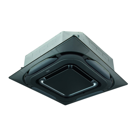
- Page 1 Installer and user reference guide Split system air conditioners FCAHG71HVEB FCAHG100HVEB Installer and user reference guide FCAHG125HVEB English Split system air conditioners FCAHG140HVEB...
-
Page 2: Table Of Contents
Table of contents Overview: Commissioning............19 Table of contents Precautions when commissioning ..........19 Checklist before commissioning..........20 To perform a test run..............20 Error codes when performing a test run ........21 1 General safety precautions 9 Hand-over to the user About the documentation ............ -
Page 3: General Safety Precautions
1 General safety precautions 18.1.7 Symptom: Noise of air conditioners (Indoor unit)..30 Symbol Explanation 18.1.8 Symptom: Noise of air conditioners (Indoor unit, For more information, see the installer and user outdoor unit)..............30 reference guide. 18.1.9 Symptom: Noise of air conditioners (Outdoor unit) ..30 18.1.10 Symptom: Dust comes out of the unit ...... -
Page 4: Installation Site
▪ Do NOT place any objects or equipment on top of the unit. Make sure installation, servicing, maintenance and repair comply with instructions from Daikin and with applicable ▪ Do NOT sit, climb or stand on the unit. legislation (for example national gas regulation) and are NOTICE executed only by authorised persons. -
Page 5: Refrigerant
1 General safety precautions Ceiling-mounted Wall-mounted Floor-standing To determine the minimum floor area unit unit unit 1 Determine the total refrigerant charge in the system (= factory m (kg) m (kg) m (kg) refrigerant charge additional refrigerant amount ≤1.842 — ≤1.842 —... -
Page 6: Brine
1 General safety precautions DANGER: RISK OF EXPLOSION CAUTION Pump down – Refrigerant leakage. If you want to pump When the refrigerant charging procedure is done or when down the system, and there is a leak in the refrigerant pausing, close valve refrigerant... -
Page 7: About The Documentation
▪ A subset of the latest technical data is available on the regional impossible. Daikin website (publicly accessible). ▪ Over-tightening the terminal screws may break them. ▪ The full set of latest technical data is available on the Daikin Business Portal (authentication required). FCAHG71~140HVEB Installer and user reference guide Split system air conditioners 4P561449-1A –... -
Page 8: For The Installer
3 About the box For the installer 3.2.2 To remove the accessories from the About the box indoor unit Overview: About the box 1× 1× 1× 8× 4× 7× This chapter describes what you have to do after the box with the indoor unit is delivered on-site. -
Page 9: Identification Label: Indoor Unit
5 Preparation 4.2.1 Identification label: Indoor unit Location About the indoor unit Use the system in the following temperature and humidity ranges for safe and effective operation. In combination with R410A outdoor units Outdoor units Cooling Heating Indoor unit Outdoor unit RZQG71~140 Outdoor –15~50°C DB –20~15.5°C WB... -
Page 10: Installation Site Requirements Of The Indoor Unit
5 Preparation ▪ Take care that in the event of a water leak, water cannot cause 5.2.1 Installation site requirements of the any damage to the installation space and surroundings. indoor unit ▪ Choose a location where the hot/cold air discharged from the unit INFORMATION or the operation noise, will NOT disturb anyone. -
Page 11: Preparing Refrigerant Piping
6 Installation ▪ B: Minimum and maximum distance to the floor: Preparing electrical wiring ▪ Minimum: 2.7 m to avoid accidental touching. 5.4.1 About preparing electrical wiring ▪ Maximum: Depends on the air flow directions and the capacity class. Also make sure the "Ceiling height" field setting corresponds with the actual situation. -
Page 12: Mounting The Indoor Unit
6 Installation ▪ Suspension bolts. Use M8~M10 suspension bolts for installation. INFORMATION Attach the hanger bracket to the suspension bolt. Fix it securely This chapter only describes installation instructions specific using a nut and washer from the upper and lower sides of the to the indoor unit. -
Page 13: Guidelines When Installing The Drain Piping
6 Installation ▪ Pipe size. Keep the pipe size equal to or greater than that of the Example If A Then connecting pipe (vinyl pipe of 25 mm nominal diameter and 32 mm outer diameter). 860 mm 10 mm 45 mm ▪ Slope. Make sure the drain piping slopes down (at least 1/100) to 910 mm 35 mm 20 mm... -
Page 14: Connecting The Refrigerant Piping
6 Installation 6 Connect the drain piping to the drain hose. ≤4 mm A-A' Plastic watering can Service drain outlet (with rubber plug). Use this outlet to drain water from the drain pan. Drain pump location Drain pipe connection (attached to the unit) Drain pipe connection Drain hose (accessory) Drain pipe... -
Page 15: Guidelines When Connecting The Refrigerant Piping
6 Installation ▪ ALWAYS use a spanner and torque wrench together to tighten the CAUTION flare nut when connecting the piping. This to prevent nut cracking ▪ Do NOT use mineral oil on flared part. and leaks. ▪ NEVER install a drier to this unit to guarantee its lifetime. -
Page 16: To Connect The Refrigerant Piping To The Indoor Unit
6 Installation Connecting the electrical wiring 6.4.1 About connecting the electrical wiring Typical workflow Connecting the electrical wiring typically consists of the following Flare’s inner surface MUST be flawless. stages: The pipe end MUST be evenly flared in a perfect circle. Making sure the power supply system complies with the Make sure the flare nut is fitted. -
Page 17: Specifications Of Standard Wiring Components
6 Installation 4 Divide the small sealing (accessory) and wrap it around the Wire type Installation method cables to prevent water from entering the unit. Seal all gaps to Stranded conductor prevent small animals from entering the system. wire with round crimp-style terminal WARNING Provide adequate measures to prevent that the unit can be... -
Page 18: Configuration
7 Configuration ▪ 2 user interface control. (2 remote controllers control 1 indoor ▪ Air flow direction unit) ▪ Air volume when thermostat control is OFF 1~ 50 Hz 220-240 V ▪ Time to clean air filter Setting: Ceiling height This setting must correspond with the actual distance to the floor, capacity class and air flow directions. -
Page 19: Commissioning
Next commissioning instructions in this chapter, a general If you want to set the slave unit as… Then commissioning checklist is also available on the Daikin Business Portal (authentication required). Unified setting 21(11) The general commissioning checklist is complementary to... -
Page 20: Checklist Before Commissioning
8 Commissioning NOTICE The stop valves (gas and liquid) on the outdoor unit are fully open. Before starting up the system, the unit MUST be energised for at least 6 hours to avoid compressor breakdown during startup. To perform a test run NOTICE This task is only applicable when using the BRC1E52 or BRC1E53 user interface. -
Page 21: Error Codes When Performing A Test Run
If the installation of the outdoor unit has NOT been done correctly, Daikin website (publicly accessible). the following error codes may be displayed on the user interface: ▪ The full set of latest technical data is available on the Daikin Error code Possible cause Business Portal (authentication required). -
Page 22: Wiring Diagram
11 Technical data 11.2 Wiring diagram 11.2.1 Unified wiring diagram legend Symbol Meaning Compressor motor For applied parts and numbering, refer to the wiring diagram on the Fan motor unit. Part numbering is by Arabic numbers in ascending order for each part and is represented in the overview below by "*"... -
Page 23: For The User
Sound power level (per speed setting, ▪ Fan only operation (air to air). if applicable) Contact details: DAIKIN INDUSTRIES CZECH REPUBLIC s.r.o. U Nové Hospody 1/1155, 301 00 Plzeň Skvrňany, Czech Republic FCAHG71~140HVEB Installer and user reference guide Split system air conditioners... -
Page 24: 15 Operation
15 Operation The indoor unit will indicate defrost operation on the display Operation Hot start In order to prevent cold air from blowing out of an indoor unit at the 15.1 Operation range start of heating operation, the indoor fan is automatically stopped. The display of the user interface shows . -
Page 25: Adjusting The Air Flow Direction
16 Energy saving and optimum operation Choose enable and confirm. 15.4 Adjusting the air flow direction Circulation Air ow Enable/Disable Refer to the operation manual of the user interface. Enable 15.4.1 About the air flow flap Return Return Setting Setting Confirm setting. -
Page 26: 17 Maintenance And Service
17 Maintenance and service ▪ If the dirt becomes impossible to clean, change the air filter Maintenance and service (= optional equipment). How to clean the air filter: 17.1 Precautions for maintenance and NOTICE service Do NOT use water of 50°C or higher. Possible consequence: Discoloration and deformation. -
Page 27: To Clean The Suction Grille
17 Maintenance and service 17.2.2 To clean the suction grille NOTICE ▪ Do NOT use gasoline, benzene, thinner polishing NOTICE powder or liquid insecticide. Possible consequence: Do NOT use water of 50°C or higher. Possible Discoloration and deformation. consequence: Discoloration and deformation. ▪... -
Page 28: After-Sales Service And Warranty
17 Maintenance and service WARNING WARNING The appliance shall be stored in a room without ▪ Do NOT modify, disassemble, remove, reinstall or continuously operating ignition sources (example: open repair the unit yourself as incorrect dismantling or flames, an operating gas appliance or an operating electric installation may cause an electric shock or fire. -
Page 29: Troubleshooting
18 Troubleshooting ▪ Dust, salt, harmful gas or oil mist such as sulphurous acid and Malfunction Measure hydrogen sulfide may be present in the air. If the system does not ▪ Check if there is no power failure. Wait ▪ The machine is started and stopped frequently or operation time is operate at all. -
Page 30: Symptom: The Fan Direction Does Not Correspond To The Setting
19 Relocation 18.1.3 Symptom: The fan direction does not 18.1.11 Symptom: The units can give off odours correspond to the setting The unit can absorb the smell of rooms, furniture, cigarettes, etc., and then emit it again. The fan direction does not correspond with the user interface display. - Page 31 Optional equipment Equipment made or approved by Daikin that can be combined with the product according to the instructions in the accompanying documentation. Field supply Equipment NOT made by Daikin that can be combined with product according instructions accompanying documentation.
- Page 32 4P561449-1A 2019.09...