
Related Manuals for Daikin FCAG35BVEB


Summary of Contents for Daikin FCAG35BVEB
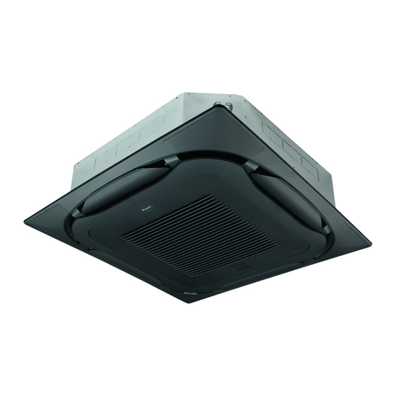
- Page 1 Installation and operation manual Split system air conditioners FCAG35BVEB FCAG50BVEB FCAG60BVEB FCAG71BVEB FCAG100BVEB Installation and operation manual FCAG125BVEB English Split system air conditioners FCAG140BVEB...
- Page 2 3P480520-12D...
-
Page 3: Table Of Contents
Using the dry program............... 14 Daikin website (publicly accessible). 12.3.1 About the dry program ..........14 ▪ The full set of latest technical data is available on the Daikin 12.3.2 To use the dry program..........14 Business Portal (authentication required). -
Page 4: For The Installer
2 About the box For the installer CAUTION About the box Appliance not accessible to the general public, install it in a secured area, protected from easy access. Indoor unit This unit, both indoor and outdoor, is suitable for installation commercial light industrial... -
Page 5: Installation
4 Installation Paper pattern for installation (upper part of the packing) Installation Screws (accessories) ▪ Ceiling opening and unit: Mounting the indoor unit ▪ Make sure the ceiling opening is within the following limits: Minimum: 860 mm to be able to fit the unit. 4.1.1 Guidelines when installing the indoor unit Maximum: 910 ... -
Page 6: Guidelines When Installing The Drain Piping
4 Installation Rising drain piping (vinyl pipe of 25 mm nominal diameter ▪ Level. Make sure the unit is level at all 4 corners using a level or a and 32 mm outer diameter) (field supply) water-filled vinyl tube. Hanging bars (field supply) ▪... -
Page 7: Connecting The Refrigerant Piping
4 Installation ▪ Remove the switch box cover (a). 4.2.1 To connect the refrigerant piping to the ▪ Connect the user interface (b). indoor unit ▪ Connect the power supply (1~ 220-240 V 50/60 Hz) and earth (c). CAUTION ▪ Reattach the switch box cover (a). Install the refrigerant piping or components in a position where they are unlikely to be exposed to any substance which may corrode components containing refrigerant,... -
Page 8: Specifications Of Standard Wiring Components
5 Configuration 1~ 50 Hz 4.3.1 Specifications of standard wiring 220-240 V components Component Specification Interconnection cable 4-core cable (indoor↔outdoor) 1.5 mm ~2.5 mm applicable for 220~240 V H05RN-F (60245 IEC 57) User interface cable Vinyl cords with 0.75 to 1.25 mm² sheath or cables (2‑core wires) Maximum 500 m H03VV-F (60227 IEC 52) - Page 9 5 Configuration If the distance to the floor is (m) Then If you want an interval of… Then (air contamination) ≤2.7 13 (23) ±2500 h (light) 10 (20) 2.7<x≤3.0 ±1250 h (heavy) 3.0<x≤3.5 No notification Setting: Decoration panel type Individual setting in a simultaneous operation system When installing or changing the decoration panel type, ALWAYS We recommend using the optional user interface to set the slave check if the correct values are set.
-
Page 10: Commissioning
6 Commissioning Action Commissioning On the user interface, set the unit to cooling operation mode. NOTICE ALWAYS operate the unit with thermistors and/or pressure 2 Start the test run sensors/switches. If NOT, burning of the compressor might Action Result be the result. Go to the home menu. -
Page 11: Error Codes When Performing A Test Run
(the currently set Daikin website (publicly accessible). outdoor unit, between outdoor unit and temperature is not ▪ The full set of latest technical data is available on the Daikin indoor units, between indoor unit and displayed) Business Portal (authentication required). -
Page 12: For The User
9 About the system Symbol Meaning Symbol Meaning DIP switch Resistor Heater Thermistor FU*, F*U, (for characteristics, Fuse Receiver refer to PCB inside your unit) Limit switch Connector (frame ground) Float switch Harness S*NPH Pressure sensor (high) H*P, LED*, V*L Pilot lamp, light emitting diode S*NPL Pressure sensor (low) -
Page 13: Before Operation
11 Before operation In combination with R410A outdoor units Before operation Outdoor units Cooling Heating WARNING RZQSG71~140 –15~46°C DB –15~15.5°C WB This unit contains electrical and hot parts. 14~28°C WB 10~27°C DB WARNING RZQ200~250 –5~46°C DB –15~15°C WB Before operating the unit, be sure the installation has been carried out correctly by an installer. -
Page 14: Operating The System
12 Operation 12.3.2 To use the dry program 12.2 Operating the system To start 12.2.1 About operating the system 1 Press the operation mode selector button on the user interface several times and select (program dry operation). ▪ To protect the unit, turn on the main power switch 6 hours before operation. -
Page 15: Maintenance And Service
13 Maintenance and service Go to the home screen. CAUTION Cool Set to After a long use, check the unit stand and fitting for damage. If damaged, the unit may fall and result in injury. °C NOTICE Do NOT wipe the controller operation panel with benzine, Press. -
Page 16: To Clean The Suction Grille
13 Maintenance and service 2 Remove the air filter. 2 Remove the suction grille. Standard panel: Standard panel: 45° Design panel: Design panel: 3 Clean the air filter. Use a vacuum cleaner or wash with water. If 3 Remove the air filter. the air filter is very dirty, use a soft brush and neutral detergent. -
Page 17: Maintenance Before A Long Stop Period
14 Troubleshooting ▪ Clean air filters and casings of indoor units (see "13.2.1 To clean WARNING filter" [ 4 15] and the air "13.2.3 To clean the air outlet and outside R410A is a non-combustible refrigerant, and R32 is a panels" [ 4 16]). mildly flammable refrigerant;... - Page 20 4P535626-1C 2019.09...