Table of Contents
Advertisement
Quick Links
Do not use this equipment before reading this manual!
Model Number:
High Rider Bare
High Rider Complete
Low Rider Bare
Low Rider Complete
Printed in the U. S. A.
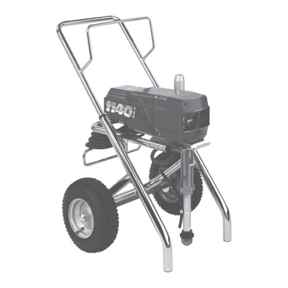
1140
Airless Sprayer
800-180
800-181
800-192
800-193
Owner's Manual
For professional use only
i
NOTE: This manual contains important warnings
NOTE: This manual contains important warnings
and instructions. Please read and retain for
and instructions. Please read and retain for
reference.
reference.
0208 © 2002 Titan Tool Inc. All rights reserved. Form No. 313-1712, REV C
Advertisement
Table of Contents

Related Manuals for Titan Tool 1140i


Summary of Contents for Titan Tool 1140i
- Page 1 Please read and retain for and instructions. Please read and retain for Low Rider Bare 800-192 reference. reference. Low Rider Complete 800-193 0208 © 2002 Titan Tool Inc. All rights reserved. Form No. 313-1712, REV C Printed in the U. S. A.
-
Page 2: Safety Precautions
Consultation with a plastic surgeon or • Use lowest possible pressure to flush equipment. reconstructive hand surgeon may be advisable. • Do not spray onto pump assembly. © Titan Tool Inc. All rights reserved. - Page 3 • For electric units — Always unplug cord from outlet before working on equipment. • Do not use the hose as a strength member to pull or lift the equipment. • Do not lift by cart handle when loading or unloading. © Titan Tool Inc. All rights reserved.
-
Page 4: Table Of Contents
This equipment produces a fluid stream at the OFF position in the black zone. extremely high pressure. Read and understand the warnings in the Safety Precautions section at the front of this manual before operating this equipment. © Titan Tool Inc. All rights reserved. -
Page 5: Preparing To Paint
Solid Yellow spray system, changing or cleaning spray tips, or 200–1800 PSI preparing for cleanup. Solid Green 1800–3300 PSI Motor Running Motor Running Indicator Indicator Programmer Port Programmer Port © Titan Tool Inc. All rights reserved. -
Page 6: Pressure Relief Procedure
OFF position in the black zone. Trigger lock 3. Unlock the gun by turning the gun Too Thick in locked position. trigger lock to the unlocked position. Arcing Gun at angle © Titan Tool Inc. All rights reserved. -
Page 7: Practice
13. Follow the “Pressure Relief Procedure” found in the Operation section of this manual. 14. Unplug the unit and store in a clean, dry area. IMPORTANT: Do not store the unit under pressure. © Titan Tool Inc. All rights reserved. -
Page 8: Maintenance
5. Make sure the handle seal is in position and thread the the valve stem to secure the valve handle in position. handle into the gun body until secure. 6. Move the gun trigger lock to the locked position. © Titan Tool Inc. All rights reserved. -
Page 9: Replacing The Motor Assembly
16. Slide the motor shroud over the motor. Make sure the shroud gasked is positioned properly. 17. Secure the motor shroud with the four motor shroud screws. © Titan Tool Inc. All rights reserved. -
Page 10: Replacing The Transducer
6. Remove, clean, and inspect the Lower Mounting Plate outlet valve cage and outlet Housing valve ball. Replace if they are worn or damaged. 7. Reassemble the valves by reversing the steps above. © Titan Tool Inc. All rights reserved. - Page 11 15. Thread the upper seal retainer Raised Lip NOTE: Repacking kit P/N 800-273 is available. For into the upper housing and best results use all parts supplied in this kit. torque to 25-30 ft. lbs. © Titan Tool Inc. All rights reserved.
-
Page 12: Français
2. Needle assembly out of adjustment 2. Adjust 3. Dirty gun 3. Clean Gun does not spray 1. No paint 1. Check fluid supply 2. Plugged filter or tip 2. Clean 3. Broken needle in gun 3. Replace © Titan Tool Inc. All rights reserved. - Page 13 2. Use a minimum of 50' (15m) of 1/4" high pressure hose 3. Tip too large or worn 3. Replace with a new or smaller tip Patents These products are covered by one or more of the following U.S. patents: 4,500,119 4,768,929 © Titan Tool Inc. All rights reserved.
-
Page 14: Español
• Se servir de la pression la plus basse possible pour vidanger s’avérer nécessaire de consulter un plasticien ou un spécialiste l’appareil. en chirurgie reconstructive de la main. • Ne pas pulvériser de produit sur la pompe. © Titan Tool Inc. Tous droits réservés. Français... - Page 15 électrique de la prise avant de travailler sur l’équipement. • N’utilisez pas le tuyau pour tirer ou soulever l’équipement. • Ne pas soulever par la poignée de chariot en chargeant ou en déchargeant. © Titan Tool Inc. Tous droits réservés. Français...
- Page 16 Puede ser • No rocíe el ensamblaje de la bomba. aconsejable consultar con un cirujano plástico o un cirujano especialista en reconstrucción de las manos. © Titan Tool Inc. Todos los derechos reservados. Español...
- Page 17 • No utilice la manguera como elemento de fuerza para tirar del equipo o levantarlo. • No levantar por la manija del carro al cargar o descargando. © Titan Tool Inc. Todos los derechos reservados. Español...
-
Page 18: Parts Listings
PRIME/SPRAY valve assembly....1 858-625 Screw............2 800-269 Fitting ............1 800-328 Knock-off nut..........1 800-267 Fitting ............1 800-300 Fluid section assembly .......1 860-002 Lock washer..........2 451-241 Siphon tube..........1 860-535 Screw............2 730-334 Hose clamp..........1 800-266 Hose (not shown) ........1 © Titan Tool Inc. All rights reserved. -
Page 19: Drive Assembly
Circuit breaker ..........1 800-366 Wire cover, 7” (not shown) ......1 800-075 Mounting plate ..........1 800-368 Wire assembly (not shown) ......1 NOTE: All electrical work should be performed by a Titan authorized service center. © Titan Tool Inc. All rights reserved. -
Page 20: Fluid Section Assembly
NOTE: When repacking the fluid section, make sure the raised lip on the bottom of the lower packing is fully outside the packing around the piston rod after insertion of the piston rod. © Titan Tool Inc. All rights reserved. -
Page 21: High Rider Cart
800-915 PRIME/SPRAY valve assembly....1 800-279 Cart (includes items 7 and 9) .....1 800-907 Plug, 1/4” ............1 335-018 Plug.............2 800-437 Transducer..........1 856-002 Washer............4 856-921 Screw............4 800-007 Axle.............1 670-109 Wheel............2 870-004 Washer............2 800-019 Cap .............2 © Titan Tool Inc. All rights reserved. -
Page 22: Siphon Set Assembly (Low Rider)
Handle assembly 800-109 Wheel spacer..........2 (includes items 1–3 and 5–7) .....1 800-593 Wheel............2 590-508 Roll pin............2 800-111 Cap .............2 856-921 Screw............4 800-112 Cart weldment (includes items 8 and 10)...1 856-002 Washer............4 700-674 Plug.............2 © Titan Tool Inc. All rights reserved. -
Page 23: Prime/Spray Assembly
Potentiometer Assy ORANGE BLACK 800-277 Electronic Control Assy GREEN Motor BLACK WHITE Relay 800-276 WHITE Indicator Lights Assembly 800-278 BLACK/RED/WHITE NOTE: All electrical work should be performed by a Titan authorized service center. © Titan Tool Inc. All rights reserved. -
Page 24: Warranty
Warranty Titan Tool, Inc., (“Titan”) warrants that at the time of delivery to the original purchaser for use (“End User”), the equipment covered by this warranty is free from defects in material and workmanship. Titan’s obligation under this warranty is limited to replacing or repairing without charge those parts which, to Titan’s reasonable satisfaction, are shown to be defective within twenty-five (25) months after sale to the End User.