
Related Manuals for TP-Link JetStream T2500G-10MPS


Summary of Contents for TP-Link JetStream T2500G-10MPS
- Page 1 Business Networking Solution Installation Guide JetStream Gigabit L2 Managed Switch T2500G-10MPS T2500G-10TS (TL-SG3210)
- Page 3 Conventions Some models featured in this guide may be unavailable in your country or region. ■ For local sales information, visit http://www.tp-link.com. The figures in Chapter 2 to Chapter 5 are for demonstration purposes only. Your ■ switch may differ in appearance from that depicted.
-
Page 4: Table Of Contents
Contents Chapter 1 Introduction ——————————— 01 Product Overview ............01 Appearance ..............01 Chapter 2 Installation ———————————— 07 Package Contents .............07 Safety Precautions ............07 Installation Tools ............09 Product Installation ...........09 Chapter 3 Lightning Protection ——————— 11 Cabling Reasonably ..........11 Connect to Ground ..........13 Chapter 4 Connection ———————————... -
Page 5: Chapter 1 Introduction
Link aggregation (LACP) increases aggregated bandwidth, optimizing the transport of business critical data. SNMP, RMON, WEB and CLI Log-in bring abundant management policies. TP-Link JetStream Gigabit L2 Managed Switch integrates multiple functions with excellent performance, and is friendly to manage, which can fully meet the need of the users demanding higher networking performance. - Page 6 Gigabit L2 Managed Switch LEDs Status Indication The switch is powered on The switch is powered off or power supply is abnormal Flashing Power supply is abnormal Flashing The switch works properly On/Off The switch works improperly A 1000Mbps device is linked to the corresponding Green port, but no activity A 10/100Mbps device is linked to the corresponding...
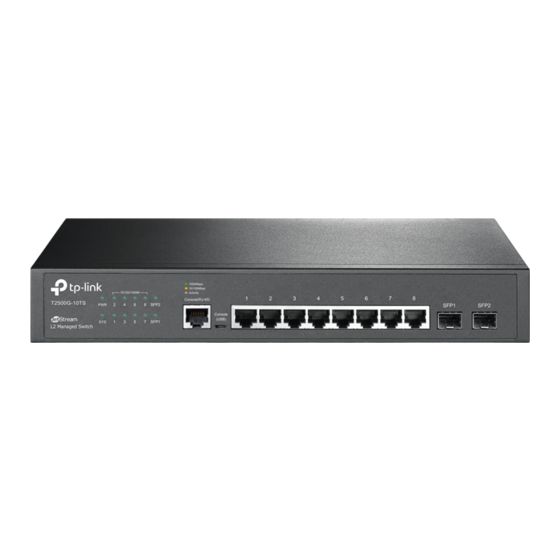
- Page 7 Gigabit L2 Managed Switch The front panel of T2500G-10MPS is shown as the following figure. Figure 1-2 Front Panel of T2500G-10MPS LEDs LED Mode Switch Button Console Port (RJ-45) Console Port (USB) 10/100/1000Mbps RJ45 Port SFP Port LEDs T2500G-10MPS has an LED mode switch button which is for switching the LED status indication.
- Page 8 Gigabit L2 Managed Switch Status Indication A 1 0 0 0 M b p s d e v i c e i s c o n n e c t e d t o t h e corresponding port, but no activity Green Flashing Data is being transmitted or received...
- Page 9 Gigabit L2 Managed Switch 10/100/1000Mbps RJ45 Port and PoE Port Designed to connect to the device with a bandwidth of 10Mbps, 100Mbps or 1000Mbps. Each has a corresponding Speed or PoE LED. SFP Port Designed to install the SFP module. T2500G-10MPS features 2 SFP transceiver ports.
- Page 10 Gigabit L2 Managed Switch Grounding Terminal The switch already comes with lightning protection mechanism. You can also ground the switch through the PE (Protecting Earth) cable of AC cord or with Ground Cable. For detailed information, please refer to Chapter 3 Lightning Protection.
-
Page 11: Chapter 2 Installation
Gigabit L2 Managed Switch Chapter 2 Installation 2.1 Package Contents Make sure that the package contains the following items. If any of the listed items is damaged or missing, please contact your distributor. One Switch One Power Cord, one Console This Installation Guide Cable and one USB Cable Two mounting brackets,eight... - Page 12 Gigabit L2 Managed Switch changes and corrosions. Too high temperature may accelerate aging of the insulation materials and can thus significantly shorten the service life of the device. For normal temperature and humidity of the device, please check the following table.
-
Page 13: Installation Tools
Gigabit L2 Managed Switch this instant current is strong enough to damage electronic devices, more effective lightning protection measures should be taken. Ensure the rack and device are well earthed. ■ Make sure the power socket has a good contact with the ground. ■... - Page 14 Gigabit L2 Managed Switch 3. Turnover the device and attach the supplied rubber feet to the recessed areas on the bottom at each corner of the device. Figure 2-1 Desktop Installation Feet Bottom of the Device Notch Rack Installation ■ To install the device in an EIA standard-sized, 19-inch rack, follow the instructions described below: 1.
-
Page 15: Chapter 3 Lightning Protection
Gigabit L2 Managed Switch Chapter 3 Lightning Protection 3.1 Cabling Reasonably In the actual network environment, you may need cable outdoors and indoors, and the requirements for cabling outdoors and indoors are different. A reasonable cabling system can decrease the damage of induced lightning to devices. Note: It’s not recommended to use Ethernet cables outdoors. - Page 16 Gigabit L2 Managed Switch Requirements for the distance between Ethernet cable and other pipelines are ■ shown in the table. Ethernet Cable Other Pipelines Min Parallel Net Min Parallel-overlapping Net Length L (mm) Height H (mm) Down-conductor 1000 Service pipe Compressed air pipe Thermal pipe (not wrapped)
-
Page 17: Connect To Ground
Gigabit L2 Managed Switch 3.2 Connect to Ground Connecting the device to ground is to quickly release the lightning over-voltage and over-current of the device, which is also a necessary measure to protect the body from electric shock. In different environments, the device may be grounded differently. The following will instruct you to connect the device to the ground in two ways, connecting to the ground via the power supply or connecting to the ground via the grounding terminal. - Page 18 Gigabit L2 Managed Switch Figure 3-2 Connecting to the Grounding Bar Switch (Rear Panel) Grounding Terminal Ground Cable Grounding Bar Note: The grounding bar and the ground cable are not provided with our product. If needed, please self purchase them. Equipotential Bonding Equipotential Bonding is the practice of intentionally electrically connecting all earthed systems to the same grounding grid or connecting the grounding grids of...
- Page 19 Gigabit L2 Managed Switch Note: The equipotential bonding cable and ground cable are not provided with our product. If needed, please self purchase it. Use Lightning Arrester Power lightning arrester and signal lightning arrester are used for lighting protection. Power lightning arrester is used for limiting the voltage surge due to a lightning. If an outdoor AC power cord should be directly connected to the device, please use a power lightning arrester.
-
Page 20: Chapter 4 Connection
Gigabit L2 Managed Switch Chapter 4 Connection 4.1 Ethernet Port Connect the Ethernet ports of the switch to the network devices by RJ45 cable as the following figure shows. Figure 4-1 Connecting the RJ45 Port RJ45 Port RJ45 Cable 4.2 SFP Port Connect the SFP port to an SFP module. -
Page 21: Verify Installation
Gigabit L2 Managed Switch Figure 4-3 Connecting the Console (RJ-45) Port Connect the Console (USB) port of the device with your computer by the USB ■ cable as the following figure shows. Figure 4-4 Connecting the Console (USB) Port Console(USB) You can also manage the device through the console port, for details please refer to the CLI Reference Guide on the resource CD. -
Page 22: Power On
Gigabit L2 Managed Switch 4.5 Power On Plug the female connector of the provided power cord into the power socket of the device, and the male connector into a power outlet as the following figure shows. Figure 4-5 Connecting to Power Supply Note: The figure is to illustrate the application and principle. -
Page 23: Chapter 5 Configuration
Gigabit L2 Managed Switch Chapter 5 Configuration 5.1 Configure the Switch via GUI Note: To log on to the GUI of the switch, the IP address of your PC should be set in the same subnet addresses of the switch. The IP address is 192.168.0.x ("x" is any number from 2 to 254), Subnet Mask is 255.255.255.0. -
Page 24: Configure The Switch Using Cli
The Micro-USB connector takes precedence over the RJ-45 connector. Install the TP-Link USB Console Driver if you are using the USB serial port for the first time on a Windows-based PC. The driver can be found on the attached CD and Download page of our official website. - Page 25 Gigabit L2 Managed Switch Parity: none ■ Stop bits: 1 ■ Flow control: none ■ 5. The DOS prompt ”T2500G-10TS>” will appear after pressing the Enter button as Figure 5-4 shows. It indicates that you can use the CLI now. Figure 5-4 Log in the Switch Logon by Telnet...
- Page 26 Gigabit L2 Managed Switch 5. Type the default user name and password (both of them are admin), then press the Enter button so as to enter User EXEC Mode. Figure 5-7 Enter into the User EXEC Mode For detailed CLI configuration instructions, please refer to the CLI Reference Guide on the resource CD.
-
Page 27: Appendix A Troubleshooting
Gigabit L2 Managed Switch Appendix A Troubleshooting What could I do if I forgot the username and password of the switch? 1. Connect the console port of the PC to the console port of the switch and open hyper terminal. 2. - Page 28 Gigabit L2 Managed Switch 2. Check if the console cable is the right type. 3. Ensure the parameters of the terminal emulation program are correct: configure Bits per second as 38400, Data bits as 8, Parity as None, Stop bits as 1, and Flow control as None.
-
Page 29: Appendix B Hardware Specifications
Gigabit L2 Managed Switch Appendix B Hardware Specifications Item Content T2500G-10TS: IEEE802.3, 802.3i, 802.3u, 802.3ab, 802.3z, 802.3ad, 802.3x, 802.1p, 802.1q, 802.1x, 802.1d, 802.1s, 802.1w Standards T2500G-10MPS: IEEE802.3, 802.3i, 802.3u, 802.3ab, 802.3z, 802.3ad, 802.3af, 802.3at, 802.3x, 802.1p, 802.1q, 802.1x, 802.1d, 802.1s, 802.1w, 802.1ab 10Base-T: UTP/STP of Cat. - Page 30 FCC STATEMENT This equipment has been tested and found to comply with the limits for a Class A digital device, pursuant to part 15 of the FCC Rules. These limits are designed to provide reasonable protection against harmful interference when the equipment is operated in a commercial environment. This equipment generates, uses, and can radiate radio frequency energy and, if not installed and used in accordance with the instruction manual, may cause harmful interference to radio communications.
- Page 31 • 插槽與開口供通風使用, 以確保本產品的操作可靠並防止過熱, 請勿堵塞或覆蓋開口。 • 請勿將本產品置放於靠近熱源的地方。 除非有正常的通風, 否則不可放在密閉位置中。 • 請不要私自打開機殼, 不要嘗試自行維修本產品, 請由授權的專業人士進行此項工作。 • 此為甲類資訊技術設備, 于居住環境中使用時, 可能會造成射頻擾動, 在此種情況下, 使用者會被要求採取某些適當的對策。 Industry Canada Statement CAN ICES-3 (A)/NMB-3(A) Explanation of the symbols on the product label Symbol Explanation AC voltage Indoor use only RECYCLING This product bears the selective sorting symbol for Waste electrical and electronic equipment (WEEE).
- Page 32 QR code. The products of TP-Link partly contain software code developed by third parties, including software code subject to the GNU General Public License (“GPL”). As applicable, the terms of the GPL and any information on obtaining access to the respective GPL Code used in TP-Link products are available to you in GPL-Code-Centre under (http://www.tp-link.com/en/support/gpl/). The respective programs are distributed WITHOUT ANY WARRANTY and are subject to the copyrights of one or more authors.