Table of Contents
Advertisement
Advertisement
Table of Contents

Related Manuals for TP-Link TL-SG3452XP


Summary of Contents for TP-Link TL-SG3452XP
- Page 1 Business Networking Solution Installation Guide JetStream L2/L2+ Managed Switch...
- Page 3 Remind to take notice. The note contains the helpful information for a better use of the product. Related Document The User Guide and CLI Reference Guide of the product are provided on Download Center. To obtain the latest product information, visit the official website: https://www.tp-link.com.
-
Page 4: Table Of Contents
Contents Chapter 1 Introduction ——————————— 01 Product Overview ............01 Appearance ...............01 Chapter 2 Installation ——————————— 11 Package Contents ............11 Safety Precautions ............11 Installation Tools ..............13 Product Installation ............13 Chapter 3 Connection ——————————— 15 Ethernet Port ..............15 SFP/SFP+ Slot ..............15 Console Port ..............15 Verify Installation .............16 Power On ................17 Initialization ................17... -
Page 5: Chapter 1 Introduction
QoS and IGMP snooping/filtering optimize voice and video application. Link aggregation (LACP) increases aggregated bandwidth, optimizing the transport of business critical data. SNMP, RMON, WEB and CLI Log-in bring abundant management policies. TP-Link JetStream L2/L2+ Managed Switch integrates multiple functions with excellent performance, and is friendly to manage, which can fully meet the need of the users demanding higher networking performance. - Page 6 JetStream L2/L2+ Managed Switch The front panel of TL-SX3016F is shown as the following figure. RJ45 Port Console Port SFP+ Slot (USB/RJ45) The front panel of TL-SG3210 is shown as the following figure. 1000Mbps 1000Mbps 10/100/1000M 10/100Mbps 100Mbps Activity Activity TL-SG3210 10/100/1000M L2+ Managed Switch...
- Page 7 Console 1000Mbps 10Gbps 1Gbps activity 10/100Mbps SFP+ Console Port 1G RJ45 Port SFP+ Slot (RJ45/USB) The front panel of TL-SG3452XP is shown as the following figure. PoE Max TL-SG3452XP Speed L2+ Managed PoE+ Switch Console(RJ45) Console(USB) 10Gbps 1Gbps activity 1000Mbps...
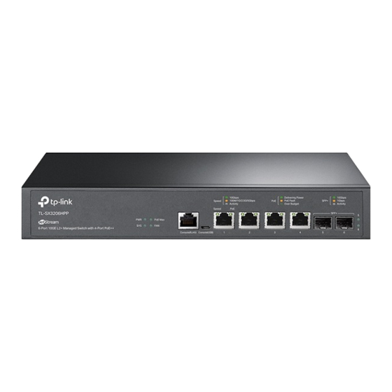
- Page 8 JetStream L2/L2+ Managed Switch LEDs For TL-SX3206HPP Indication On: The switch is powered on. Off: The switch is powered off or power supply is abnormal. Flashing: Power supply is abnormal. Flashing: The switch works properly. On or Off: The switch works improperly. On: The remaining PoE power is ≤...
- Page 9 JetStream L2/L2+ Managed Switch For TL-SX3008F Indication On: The switch is powered on. Off: The switch is powered off or power supply is abnormal. Flashing: Power supply is abnormal. Flashing: The switch works properly. On or Off: The switch works improperly. Green On: Running at 10 Gbps, but no activity.
- Page 10 JetStream L2/L2+ Managed Switch For TL-SG3210XHP-M2 Indication On: The switch is powered on. Off: The switch is powered off or power supply is abnormal. Flashing: Power supply is abnormal. Flashing: The switch works properly. On or Off: The switch works improperly. On: The remaining PoE power is ≤...
- Page 11 JetStream L2/L2+ Managed Switch Indication Green On: Running at 1000 Mbps, but no activity. Green Flashing: Running at 1000 Mbps and transmitting or receiving data. Yellow On: Running at 100 Mbps, but no activity. Port 49–52/SFP Yellow Flashing: Running at 100 Mbps and transmitting or receiving data. Off: No device is linked to the corresponding port.
- Page 12 Yellow On: Running at 1 Gbps, but no activity. Yellow Flashing: Running at 1 Gbps and transmitting or receiving data. Off: No device is linked to the corresponding port. For TL-SG3428MP, TL-SG3428XMP, TL-SG3452P and TL-SG3452XP Indication On: The switch is powered on.
- Page 13 Yellow Flashing: Running at 1 Gbps and transmitting or receiving data. Off: No device is linked to the corresponding port. Note: For TL-SG3428XMP/TL-SG3452XP Console Port Designed to connect with a computer for monitoring and configuring the switch. When the switch has an RJ45 console port and a micro-USB console port, console input is active on only one console port at a time.
- Page 14 PE (Protecting Earth) cable of AC cord or with Ground Cable. For detailed lightning protection measures, go to https://www.tp-link.com/support, search the model number of your switch and go to the product Support web page, refer to the Lightning Protection Guide from the Related Documents: https://www.tp-link.com/us/configuration-guides/lightning_protection_guide/.
-
Page 15: Chapter 2 Installation
JetStream L2/L2+ Managed Switch Chapter 2 Installation Package Contents Make sure that the package contains the following items. Please contact your distributor, if any of the listed items is damaged or missing. The figures are for demonstration only. The actual items may differ in appearance and quantity from the depicted. - Page 16 JetStream L2/L2+ Managed Switch Keep the equipment room at an appropriate level of temperature and humidity. Too much or too little humidity may lead to bad insulation, leakage of electricity, mechanical property changes, and corrosion. High temperatures may accelerate aging of the insulation materials, significantly shortening the service life of the device.
-
Page 17: Installation Tools
Use the signal SPD (Surge Protective Device) when wiring outdoor. ■ Note: For detailed lightning protection measures, go to https://www.tp-link.com/support, search the model number of your switch and go to the product Support web page, refer to the Lightning Protection Guide from the Related Documents: https://www.tp-link.com/us/configuration-guides/lightning_protection_guide/. - Page 18 JetStream L2/L2+ Managed Switch Figure 2-1 Desktop Installation Feet Bottom of the Device Notch Rack Installation ■ To install the device in an EIA standard-sized, 19-inch rack, follow the instructions described below: 1. Check the efficiency of the grounding system and the stability of the rack. 2.
-
Page 19: Chapter 3 Connection
JetStream L2/L2+ Managed Switch Chapter 3 Connection Ethernet Port Connect an Ethernet port of the switch to the computer by RJ45 cable as the following figure shows. Figure 3-1 Connecting the RJ45 Port RJ45 Port RJ45 Cable SFP/SFP+ Slot The following figure demonstrates the connection of SFP/SFP+ slot to an SFP/SFP+ module. Figure 3-2 Inserting the SFP/SFP+ Module SFP/SFP+ Slot... -
Page 20: Verify Installation
JetStream L2/L2+ Managed Switch Connect the console (RJ45) port of the device with your computer by the console cable as the following figure shows. Figure 3-3 Connecting the Console (RJ45) Port Connect the console (USB) port of the device with your computer by the USB cable (not provided) as the following figure shows. -
Page 21: Power On
JetStream L2/L2+ Managed Switch Power On Plug the female connector of the provided power cord into the power socket of the device and plug the positive connector into a power outlet as the following figure shows. Make sure that the voltage of the power supply meets the requirement of the input voltage (100-240 V~ 50/60 Hz). -
Page 22: Chapter 4 Configuration
3. After a successful login, the main page will appear. You can click the menus on the top side and left side to configure the corresponding functions. For the detailed configurations, refer to the User Guide and CLI Guide. The guides can be found on the download center of our official website: https://www.tp-link.com/support/download/. Using the CLI ■... -
Page 23: Controller Mode
None For the detailed configurations, refer to the User Guide and CLI Guide. The guides can be found on the download center of our official website: https://www.tp-link.com/download-center.html Note: For certain devices, you may need to change the password the first time you log in, which will better protect your network and devices. - Page 24 Launch a web browser and enter https://omada.tplinkcloud.com in the address bar. Enter your TP-Link ID and password to log in. Click + Add Controller and choose Hardware Controller to add your controller. Then you can further configure the controller.
- Page 25 Make sure that Cloud Access is enabled on your controller and your controller has been bound with your TP-Link ID. On the Omada Controller’s web page, go to Settings > Cloud Access to enable Cloud Access and bind your TP-Link ID. If you have set it up in the quick setup, skip this step.
-
Page 26: Appendix A Troubleshooting
JetStream L2/L2+ Managed Switch Appendix A Troubleshooting Q1. What could I do if I forgot the username and password of the switch? Connect the console port of the PC to the console port of the switch and open a terminal emulation program. -
Page 27: Appendix B Specifications
(maximum 100 m) (For TL-SX3206HPP) 100BASE-FX/LX10/BX10: MMF, SMF (For TL-SG3210, TL-SG3452, TL-SG3452P) 1000BASE-SX/LX/LX10/BX10: MMF, SMF 10GBASE-SR/LR: MMF, SMF (For TL-SX3206HPP, TL-SG3210XHP-M2, TL-SG3428X, TL-SG3428XMP, TL- SG3452X, TL-SG3452XP) 10GSFP+CU SFP+ Direct Attach Cable (TXC432-CU1M, TXC432-CU3M) (For TL-SX3206HPP, TL-SG3428X, TL-SG3428XMP, TL-SG3452X, TL-SG3452XP) Appendix B Specifications... - Page 28 TL-SG3428XMP: PWR, SYS, PoE Max, FAN, Speed or PoE, SFP+, Speed, PoE TL-SG3452, TL-SG3452X: PWR, SYS, 10/100/1000Mbps, Port 49–52 TL-SG3452P, TL-SG3452XP: PWR, SYS, Speed, PoE Max, FAN, PoE, Port 1–52 TL-SG3452, TL-SG3452P, TL-SG3452X, TL-SG3452XP: 0 °C to 40 °C (32 °F to 104 °F)
- Page 29 The original EU Declaration of Conformity may be found at https://www.tp-link.com/en/support/ce/ UK Declaration of Conformity TP-Link hereby declares that the device is in compliance with the essential requirements and other relevant provisions of the Electromagnetic Compatibility Regulations 2016 and Electrical Equipment (Safety) Regulations 2016.
- Page 30 Продукт сертифіковано згідно с правилами системи УкрСЕПРО на відповідність вимогам нормативних документів та вимогам, що передбачені чинними законодавчими актами України. Safety Information • Keep the device away from water, fire, humidity or hot environments. • Do not attempt to disassemble, repair, or modify the device.If you need service, please contact •...
- Page 32 To ask questions, find answers, and communicate with TP-Link users or engineers, please visit https://community.tp-link.com to join TP-Link Community. For technical support, the user guide and other information, please visit https://www.tp-link.com/support, or simply scan the QR code. If you have any suggestions or needs on the product guides, welcome to email techwriter@tp-link.com.cn.