D-Link AirPlus G DI-524UP Manual
802.11g/ 2.4 ghz wireless broadband router with print server
Hide thumbs
Also See for AirPlus G DI-524UP:
- Owner's manual (92 pages) ,
- Quick installation manual (11 pages) ,
- Quick instruction manual (12 pages)

Related Manuals for D-Link AirPlus G DI-524UP


Summary of Contents for D-Link AirPlus G DI-524UP
- Page 1 D-Link AirPlus G DI-524UP 802.11g/ 2.4 GHz Wireless Broadband Router with Print Server Manual Building Networks for People...
-
Page 2: Table Of Contents
Contents Package Contents ................3 Introduction ................... 4 Wireless Basics ..................8 Getting Started ..................11 Using the Configuration Menu ............12 Installing the Print Server Software ............ 40 Networking Basics ................42 Troubleshooting .................. 57 Technical Specifications ..............64 Frequently Asked Questions .............. 67 Contacting Technical Support ............. -
Page 3: Package Contents
Package Contents Contents of Package: D-Link AirPlus G DI-524UP 802.11/2.4GHz Wireless Router Power Adapter-DC 5V, 2A Manual and Warranty on CD Quick Installation Guide Ethernet Cable (All the DI-524UP’s Ethernet ports are Auto-MDIX) Note: Using a power supply with a different voltage rating than the one included with the DI-524UP will cause damage and void the warranty for this product. -
Page 4: Introduction
Unlike most routers, the DI-524UP provides data transfers at up to 108 Mbps (compared to the standard 54 Mbps) when used with other D-Link AirPlus G products. The 802.11g standard is backwards compatible with 802.11b products. This means that you do not need to change your entire network to maintain connectivity. - Page 5 Connections All Ethernet Ports (WAN and LAN) are auto MDI/MDIX, meaning you can use either a straight-through or a crossover Ethernet cable. USB Printer Port Pressing the Connect to the printer Reset Button using a USB cable. restores the This feature is used to router to its share the printer on the original factory...
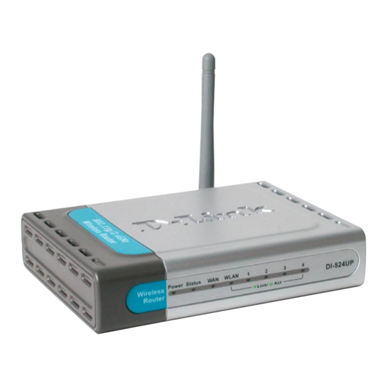
- Page 6 LEDs WLAN LED A solid light indicates that the wireless segment is ready. This LED blinks during wireless data transmission LOCAL POWER LED NETWORK LED A solid light A solid light indicates indicates a proper a connection to an connection to the Ethernet-enabled power supply computer on ports...
- Page 7 Features Fully compatible with the 802.11g standard to provide a wireless data rate of up to 54Mbps Backwards compatible with the 802.11b standard to provide a wireless data rate of up to 11Mbps WPA (Wi Fi Protected Access) authorizes and identifies users based on a secret key that changes automatically at a regular interval, for example: ...
-
Page 8: Wireless Basics
D-Link wireless products will allow you access to the data you want, when and where you want it. You will be able to enjoy the freedom that wireless networking brings. - Page 9 Wireless Basics (continued) Standards-Based Technology The DI-524UP Wireless Broadband Router utilizes the new 802.11g standard. The IEEE 802.11g standard is an extension of the 802.11b standard. It increases the data rate up to 54 Mbps within the 2.4GHz band, utilizing OFDM technology. This means that in most environments, within the specified range of this device, you will be able to transfer large files quickly or even watch a movie in MPEG format over your network without noticeable delays.
- Page 10 Wireless Basics (continued) Installation Considerations The D-Link AirPlus G DI-524UP lets you access your network, using a wireless connection, from virtually anywhere within its operating range. Keep in mind, however, that the number, thickness and location of walls, ceilings, or other objects that the wireless signals must pass through, may limit the range.
-
Page 11: Getting Started
Connect the Cable or DSL modem to the DI-524UP Wireless Broadband Router (see the printed Quick Installation Guide included with your router.) If you are connecting a desktop computer to your network, install the D-Link AirPlus G DWL-G510 wireless PCI adapter into an available PCI slot on your desktop computer. -
Page 12: Using The Configuration Menu
Using the Configuration Menu Whenever you want to configure your network or the DI-524UP, you can access the Configuration Menu by opening the web-browser and typing in the IP Address of the DI-524UP. The DI-524UP default IP Address is shown at right: http://192.168.0.1 Open the web browser ... - Page 13 Using the Configuration Menu (continued) Home > Wireless Network ID(SSID)- Service Set Identifier (SSID) is the name designated for a specific wireless local area network (WLAN). The SSID’s factory default setting is default. The SSID can be easily changed to connect to an existing wireless network or to establish a new wireless network.
- Page 14 Using the Configuration Menu (continued) Home > WAN > Dynamic IP Address Dynamic Choose Dynamic IP Address to obtain IP Address information IP Address- automatically from your ISP. Select this option if your ISP does not give you any IP numbers to use. This option is commonly used for Cable modem services.
- Page 15 Using the Configuration Menu (continued) Home > WAN > Static IP Address Static IP Address- Choose Static IP Address if all WAN IP information is provided to you by your ISP. You will need to enter in the IP address, subnet mask, gateway address, and DNS address(es) provided to you by your ISP.
- Page 16 Using the Configuration Menu (continued) Home > WAN > PPPoE Please be sure to remove any existing PPPoE client software installed on your computers. Choose PPPoE (Point to Point Protocol over E t h e r n e t ) i f y o u r ISP uses a PPPoE c o n n e c t i o n .
- Page 17 Using the Configuration Menu (continued) Home > WAN > PPPoE continued MTU- Maximum Transmission Unit-1492 is the default setting-you may need to change the MTU for optimal performance with your specific ISP. Auto-reconnect- If enabled, the DI-524UP will automatically connect to your ISP after your system is restarted or if the PPPoE connection is dropped.
- Page 18 Using the Configuration Menu (continued) Home > DHCP DHCP stands for Dynamic Host Control Protocol. The DI-524UP has a built-in DHCP server. The DHCP Server will automatically assign an IP address to the computers on the LAN/private network. Be sure to set your computers to be DHCP clients by setting their TCP/IP settings to “Obtain an IP Address Automatically.”...
- Page 19 Using the Configuration Menu (continued) Advanced > Virtual Server The DI-524UP can be configured as a virtual server so that remote users accessing Web or FTP services via the public IP address can be automatically redirected to local servers in the LAN (Local Area Network). The DI-524UP firewall feature filters out unrecognized packets to protect your LAN network so all computers networked with the DI-524UP are invisible to the outside world.
- Page 20 Using the Configuration Menu (continued) Advanced > Virtual Server continued Select Enabled or Disabled Virtual Server- Name- Enter the name referencing the virtual service Private IP- The server computer in the LAN (Local Area Network) that will be providing the virtual services. Protocol Type- The protocol used for the virtual service Private Port-...
- Page 21 Using the Configuration Menu (continued) Advanced > Virtual Server continued Click on this icon to edit the virtual service Click on this icon to delete the virtual service Example #2: If you have an FTP server that you wanted Internet users to access by WAN port 2100 and only during the weekends, you would need to enable it as such.
- Page 22 Using the Configuration Menu (continued) Advanced > Applications Some applications require multiple connections, such as Internet gaming, video conferencing, Internet telephony and others. These applications have difficulties working through NAT (Network Address Translation). Special Applications makes some of these applications work with the DI-524UP. If you need to run applications that require multiple connections, specify the port normally associated with an application in the “Trigger Port”...
- Page 23 Using the Configuration Menu (continued) Advanced > Filters > IP Filters Filters are used to deny or allow LAN (Local Area Network) computers from accessing the Internet. The DI-524UP can be setup to deny internal computers by their IP or MAC addresses.
- Page 24 Using the Configuration Menu (continued) Advanced > Filters > URL Blocking URL Blocking is used to deny LAN computers from accessing specific web sites by the URL. A URL is a specially formatted text string that defines a location on the Internet. If any part of the URL contains the blocked word, the site will not be accessible and the web page will not display.
- Page 25 Using the Configuration Menu (continued) Advanced > Filters > MAC Filters Use MAC (Media Access Control) Filters to allow or deny LAN (Local Area Network) computers by their MAC addresses from accessing the Network. You can either manually add a MAC address or select the MAC address from the list of clients that are currently connected to the Broadband Router.
- Page 26 Using the Configuration Menu (continued) Advanced > Filters > Domain Blocking Domain Blocking is used to allow or deny LAN (Local Area Network) computers from accessing specific domains on the Internet. Domain blocking will deny all requests to a specific domain such as http and ftp. It can also allow computers to access specific sites and deny all other sites.
- Page 27 Using the Configuration Menu (continued) Advanced > Firewall Firewall Rules is an advanced feature used to deny or allow traffic from passing through the DI-524UP. It works in the same way as IP Filters with additional settings. You can create more detailed access rules for the DI-524UP. When virtual services are created and enabled, it will also display in Firewall Rules.
- Page 28 Using the Configuration Menu (continued) Advanced > DDNS Users who have a Dynamic DDNS account may use this feature on the DI-524UP. Provider- Select from the list of DDNS servers available. Host Name- Enter your DDNS account host name. Username/Email- Enter your DDNS account username.
- Page 29 Using the Configuration Menu (continued) Advanced > DMZ If you have a client PC that cannot run Internet applications properly from behind the DI-524UP, then you can set the client up for unrestricted Internet access. It allows a computer to be exposed to the Internet. This feature is useful for gaming purposes. Enter the IP address of the internal computer that will be the DMZ host.
- Page 30 Using the Configuration Menu (continued) Advanced > Performance Beacon Interval- Beacons are packets sent by an Access Point to synchronize a wireless network. Specify a value. 100 is the default setting and is recommended. RTS Threshold- This value should remain at its default setting of 2432. If incon- sistent data flow is a problem, only a minor modification should be made.
- Page 31 Using the Configuration Menu (continued) Tools> Admin At this page, the DI-524UP administrator can change the system password. There are two accounts that can access the Broadband Router’s Web-Management interface. They are admin and user. Admin has read/write access while user has read-only ac- cess.
- Page 32 Using the Configuration Menu (continued) Tools > Time Default NTP is short for Network Time Protocol. NTP synchronizes NTP Server- computer clock times in a network of computers. This field is optional. Time Zone- Set Device Date and Time: To manually input the time. Enter the values in these fields for the Year, Month, Day, Hour, Minute, and Second.
- Page 33 Using the Configuration Menu (continued) Tools > System The current system settings can be saved as a file onto the local hard drive. The saved file or any other saved setting file can be loaded back on the Broadband Router. To reload a system settings file, click on Browse to browse the local hard drive and locate the system file to be used.
- Page 34 Click on Browse to browse the local hard drive and locate the firmware to be used for the update. Please check the D-Link support site for firmware updates at http://support.dlink.com. You can download firmware upgrades to your hard drive from the D-Link support site.
- Page 35 Using the Configuration Menu (continued) Tools > Misc The Ping Test is used to send Ping packets to test if a computer is on the Ping Test- Internet. Enter the IP Address that you wish to Ping, and click Ping Restart Click Reboot to restart the DI-524UP Device-...
- Page 36 Using the Configuration Menu (continued) Status > Device Info This page displays the current information for the DI-524UP. It will display the LAN, WAN and MAC address information. If your WAN connection is set up for a Dynamic IP address then a Release button and a Renew button will be displayed.
- Page 37 Using the Configuration Menu (continued) Status > Log The Broadband Router keeps a running log of events and activities occurring on the Router. If the device is rebooted, the logs are automatically cleared. You may save the log files under Log Settings. View Log- First Page - The first page of the log Last Page - The last page of the log...
- Page 38 Using the Configuration Menu (continued) Status > Log > Log Settings Not only does the Broadband Router display the logs of activities and events, it can setup to send these logs to another location. SMTP Server/ The address of the SMTP server that will be used to send the logs IP Address - Email Address - The email address to which the logs will be sent.
- Page 39 Using the Configuration Menu (continued) Status > Stats The screen above displays theTraffic Statistics. Here you can view the amount of pack- ets that pass through the DI-524UP on both the WAN and the LAN ports. The traffic counter will reset if the device is rebooted. Status >...
-
Page 40: Installing The Print Server Software
Installing the print Server Software... - Page 41 Installing the print Server Software (continued) Select the destination folder. Click Next Then, the setup program will begin to install the programs into the destination folder. When the following window is displayed. Click Finish Click...
-
Page 42: Networking Basics
Networking Basics Using the Network Setup Wizard in Windows XP In this section you will learn how to establish a network at home or work, using Microsoft Windows XP. Note: Please refer to websites such as http://www.homenethelp.com http://www.microsoft.com/windows2000 for information about networking computers using Windows 2000, ME or 98. - Page 43 Networking Basics Please follow all the instructions in this window: Click Next In the following window, select the best description of your computer. If your computer connects to the internet through a gateway/router, select the second option as shown. Click Next...
- Page 44 Networking Basics Enter a Computer description and a Computer name (optional.) Click Next Enter a Workgroup name. All computers on your network should have the same Workgroup name. Click Next...
- Page 45 Networking Basics Please wait while the Network Setup Wizard applies the changes. When the changes are complete, click Next. Please wait while the Network Setup Wizard configures the computer. This may take a few minutes.
- Page 46 Networking Basics In the window below, select the option that fits your needs. In this example, Create a Network Setup Disk has been selected. You will run this disk on each of the computers on your network. Click Next. Insert a disk into the Floppy Disk Drive, in this case drive A. Click Next.
- Page 47 Networking Basics Please read the information under Here’s how in the screen below. After you complete the Network Setup Wizard you will use the Network Setup Disk to run the Network Setup Wizard once on each of the computers on your network. To continue click Next.
- Page 48 Networking Basics Please read the information on this screen, then click Finish to complete the Network Setup Wizard. The new settings will take effect when you restart the computer. Click Yes to restart the computer. You have completed configuring this computer. Next, you will need to run the Network Setup Disk on all the other computers on your network.
- Page 49 Networking Basics Naming your Computer To name your computer, please follow these directions:In Windows XP: Click Start (in the lower left corner of the screen) Right-click on My Computer Select Properties and click Select the Computer Name Tab in the System Properties window.