
Related Manuals for Amprobe AM-250


Summary of Contents for Amprobe AM-250
- Page 1 AM-250 Digital Multimeter Users Manual • Mode d’emploi • Bedienungshandbuch • Manual d’Uso • Manual de uso...
- Page 3 AM-250 Digital Multimeter Users Manual June 2010, Rev.2 ©2010 Amprobe Test Tools. All rights reserved. Printed in Taiwan...
- Page 4 “Where to Buy” section on www.amprobe.com for a list of distributors near you. Additionally, in the United States and Canada In-Warranty repair and replacement units can also be sent to a Amprobe® Test Tools Service Center (see next page for address). Non-Warranty Repairs and Replacement – US and Canada Non-warranty repairs in the United States and Canada should be sent to a Amprobe®...
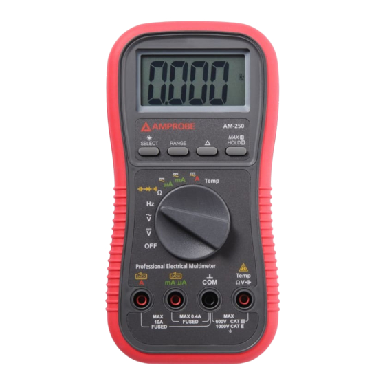
- Page 5 AM-250 Digital Multimeter 3-3/4 digits 4000 counts LCD display Push-buttons for special functions & features Selector to turn the Power On or Off and select a function Input Jack (+) for 10A (20A for 30sec) current function Input Jack (+) for all functions EXCEPT current (µA, mA, A) function...
-
Page 6: Table Of Contents
CONTENTS SYMBOLS .......................1 UNPACKING AND INSPECTION ................2 INTRODUCTION .....................2 OPERATION ......................2 e Resistance, and Continuity functions ............3 Diode test,Capacitance functions ..............4 µA, mA, and A Current functions ..............5 Beep-Jack™ Input Warning ................5 Temperature function ..................6 Relative zero mode ..................6 Backlighted display ...................6 Manual or Auto-ranging ..................7 HOLD .........................7 MAX ........................7... -
Page 7: Symbols
SYMBOLS � Battery Refer to the manual Double Insulated Dangerous Voltage Alternating Current Earth Ground Direct Current Fuse Conform to relevant � � Complies with EU directives Australian standards Do not dispose of this Underwriters > product as unsorted Laboratories. municipal waste [Note: Canadian and US.] Audible tone... -
Page 8: Unpacking And Inspection
If any of the items are damaged or missing, return the complete package to the place of purchase for an exchange. INTRODUCTION Multimeter AM-250 can be used to measure voltage, resistance, capacitance, frequency, current and temperature; It is an electronic measuring instrument that combines several measurement functions in one unit. AM-250 multimeter... -
Page 9: Resistance, And Continuity Functions
Note: 1) AC 400.0mV range selection is by RANGE button manually, and is specified from AC 10mV and up. 2) DC 400.0mV range is designed with 1000Me high input impedance for least current drain in measuring small signals, and can cope better with most commercially available voltage output transducers and adapters. -
Page 10: Diode Test,Capacitance Functions
Caution � Using Resistance, Continuity, Diode or Capacitance function in a live circuit will produce false results and may damage the instrument. In many cases the suspected component must be disconnected from the circuit to obtain an accurate measurement reading. Diode test,Capacitance functions Defaults at e. -
Page 11: Μa, Ma, And A Current Functions
Caution � Discharge capacitors before making any measurement. Large value capacitors should be discharged through an appropriate resistance load µA, mA, and A Current functions Default at DC. Press SELECT button momentarily to select AC. Caution � When measuring a 3-phase system, special attention should be taken to the phase-to-phase voltage which is significantly higher than the phase- to-earth voltage. -
Page 12: Temperature Function
Press SELECT button momentarily to select degree F (Fahrenheit). You can also use a plug adapter (Optional purchase) with banana pins to type-K socket to adapt other type-K standard mini plug temperature probes (refer to www. amprobe.com). Relative zero mode... -
Page 13: Manual Or Auto-Ranging
Manual or Auto-ranging Press the RANGE button momentarily to select manual-ranging mode, and the meter will remain in the range it was in, the LCD symbol turns off. Press the button momentarily again to step through the ranges. Press and hold the button for 1 second or more to resume auto-ranging mode. - Page 14 Power Consumption: 3.2 mA typical Low Battery: Below approx. 2.4V Sleep Mode Timing: Idle for 30 minutes Sleep Mode Consumption: 300µA typical for AM-250; 360µA typical for AM- Dimension: L193mm X W97mm X H46 (7.60 X 3.82 X 1.81 IN) Weight: 370 g (0.816lb) Special Features: 25ms Max Hold;...
- Page 15 CENELEC DIRECTIVES The instruments conform to CENELEC Low-voltage directive 73/23/EEC and Electromagnetic compatibility directive 89/336/EEC � - EMC: Conforms to EN61326-1. This product complies with requirements of the following European Community Directives: 89/ 336/ EEC (Electromagnetic Compatibility) and 73/ 23/ EEC (Low Voltage) as amended by 93/ 68/ EEC (CE Marking).
- Page 16 DC Voltage Range Accuracy 400.0 mV 0.3% + 4d 4.000V, 40.00V, 400.0V 0.5% + 3d 1000V 1.0% + 4d NMRR:>50dB @ 50/60Hz CMRR:>120dB @ DC, 50/60Hz, Rs=1ke Input Impedance: 10Me, 30pF nominal (1000Me for 400.0mV range) Type-K Temperature Range Accuracy* -20 °C to 300 °C 2% + 3 °C -4 °F to 572 °F...
- Page 17 Max Hold (Voltage & Current) Specified accuracy ± 50 digits for changes > 25ms in duration DC Current Range Accuracy Burden Voltage 400.0µA 2.0% + 5d 0.15mV/µA 4000µA 1.2% + 3d 0.15mV/µA 40.00mA 2.0% + 5d 3.3mV/mA 400.0mA 1.2% + 3d 3.3mV/mA 4.000A 2.0% + 5d...
- Page 18 Capacitance Range* Accuracy** 500.0nF, 5.000µF, 50.00µF, 500.0µF, 3.5%*** + 6d 3000µF *Additional 50.00nF range accuracy is not specified **Accuracies with film capacitor or better ***Specified with battery voltage above 2.8V (approximately half full battery). Accuracy decreases gradually to 12% at low battery warning voltage of approximately 2.4V Hz Frequency Range*...
-
Page 19: Maintenance And Repair
MAINTENANCE AND REPAIR If there appears to be a malfunction during the operation of the meter, the following steps should be performed in order to isolate the cause of the problem. 1.Check the battery. Replace the battery immediately when the “... -
Page 20: Battery Replacement
Battery replacement: Loosen the 2 screws from the battery access door of the case bottom. Lift the battery access door and thus the battery compartment up. Replace the battery. Re-fasten the screws. Fuse replacement: Loosen the 4 screws from the case bottom. Lift the end of the case bottom nearest the input jacks until it unsnaps from the case top. - Page 23 AM-270 Industrial Multimeter with Bar-graph Display Users Manual • Mode d’emploi • Bedienungshandbuch • Manual d’Uso • Manual de uso...
- Page 25 AM-270 Industrial Multimeter with Bar-graph Display Users Manual May 2010, Rev.1 ©2010 Amprobe Test Tools. All rights reserved. Printed in Taiwan...
- Page 26 “Where to Buy” section on www.amprobe.com for a list of distributors near you. Additionally, in the United States and Canada In-Warranty repair and replacement units can also be sent to a Amprobe® Test Tools Service Center (see next page for address). Non-Warranty Repairs and Replacement – US and Canada Non-warranty repairs in the United States and Canada should be sent to a Amprobe®...
- Page 27 AM-270 Industrial Multimeter with Bar-graph Display 3-4/5 digits 5000 counts LCD display Push-buttons for special functions & features Selector to turn the Power On or Off and select a function Input Jack for 10A (20A for 30sec) current function Input Jack for all functions EXCEPT current (µA, mA, A) functions Common (Ground reference) Input Jack for all functions Input Jack for milli-amp and micro-amp current functions...
- Page 28 CONTENTS SYMBOLS .......................1 UNPACKING AND INSPECTION ................3 FEATURES .......................3 OPERATION ......................4 DC Voltage, AC Voltage, & Hz Frequency Functions ........4 Capacitance, Diode Test Function ............5 Temperature Function ..................6 Resistance, Continuity Functions ............8 Auto Leads Resistance Calibration ..............8 µA, mA, and A Current Functions ..............9 PC-COMM Computer Interface Capabilities ...........10 50ms MAX/MIN at Fast 20/s Measurement Mode ...........10 0.8ms CREST Capture Mode ................10...
-
Page 29: Symbols
SYMBOLS � Caution ! Risk of electric shock � Caution ! Refer to the explanation in this Manual � Double Insulation or Reinforced insulation � Alternating Current (AC). � Direct Current (DC). Fuse � Earth (Ground) Please remove all the test leads before preforming maintenance, �... - Page 30 Measurement Category IV (CAT IV) is for measurements performed at the source of the low-voltage installation. Examples are electricity meters and measurements on primary overcurrent protection devices and ripple control units. Measurement Category III (CAT III) is for measurements performed in the building installation.
-
Page 31: Unpacking And Inspection
CENELEC Directives The instruments conform to CENELEC Low-voltage directive 2006/95/EC and Electromagnetic compatibility directive 2004/108/EC UNPACKING AND INSPECTION Your shipping carton should include: 1 AM-270 Meter 1 Test Leads (1 pair) 1 K Type thermal couple with banana plug 1 Users Manual 1 Single Alkaline 9V battery;... -
Page 32: Operation
• Overheated transformers, generators and motors to burn out faster than normal • Circuit breakers to trip prematurely • Fuses to blow • Neutrals to overheat due to the triplen harmonics present on the neutral • Bus bars and electrical panels to vibrate Crest Factor Crest Factor is the ratio of the Crest (instantaneous peak) value to the True RMS value, and is commonly used to define the dynamic range of a True RMS... -
Page 33: Capacitance, Diode Test Function
Note: Input sensitivity varies automatically with function range selected before activating the Hz function. mV function has the highest (300mV) and the 1000V range has the lowest (300V). It is recommended to first measure the signal voltage (or current) level then activate the Hz function in that voltage (or current) range to automatically set the most appropriate trigger level. -
Page 34: Temperature Function
Normal forward voltage drop (forward biased) for a good silicon diode is between 0.400V to 0.900V. A reading higher than that indicates a leaky diode (defective). A zero reading indicates a shorted diode (defective). An OL indicates an open diode (defective). Reverse the test leads connections (reverse biased) across the diode. - Page 35 Note: Be sure to insert the banana plug K-type temperature bead probe Bkp60 with correct polarities.
-
Page 36: Resistance, Continuity Functions
Resistance, Continuity Functions Default at . Press SELECT button momentarily to select Continuity function that is convenient for checking wiring connections and operation of switches. A continuous beep tone indicates a complete wire. �CAUTION Using resistance or continuity function in a live circuit will produce false results and may damage the meter. -
Page 37: Μa, Ma, And A Current Functions
The shortcut is to short the test leads in auto-ranging resistance mode until the meter enters the lowest 50 range automatically, press the RANGE button momentarily to get the “Shrt” prompt, then wait about 3 more seconds until the display shows zero. Note: The calibration stays until you change ranges, functions, or go back to auto-ranging mode. -
Page 38: Pc-Comm Computer Interface Capabilities
PC-COMM Computer Interface Capabilities The instrument equips with an optical isolated interface port at the meter back for data communication. Optional purchase PC interface kit USB-KIT3 is required to connect the meter to the PC computer. The USB-KIT3 Data Recording System software equips with a digital meter, an analog meter, a comparator meter, and a Data Graphical recorder display. -
Page 39: Backlighted Displaye
Backlighted Display Press the SELECT button for 1 second or more to turn on or off the display backlight function. The backlight will also be turned off automatically after 30 seconds to extend battery life. Hold The hold function freezes the display for later view. Press the HOLD button momentarily to activate or to exit the hold function Zoom 5x Analog Pointer The Zoom mode analog pointer magnifies up to 5 times the regular analog bar... -
Page 40: Relative Mode
Relative Mode Relative zero allows the user to offset the meter consecutive measurements with the displaying reading as the reference value. Practically all displaying readings can be set as relative reference value including MAX/MIN feature readings. Press the button momentarily to activate and to exit relative zero mode. -
Page 41: Beep-Jack™ Input Warning
Beep-Jack Input Warning ™ The meter beeps as well as displays “InErr” to warn the user against possible damage to the meter due to improper connections to the µA, mA, or A input jacks when other function (like voltage function) is selected. Set Beeper Off Press the Hz button while turning the meter on to disable the push button operating beeper feature. - Page 42 Pollution degree: Storage temperature: -20°C to 60°C (-4°F to 140°F), < 80% R.H. (With battery removed) Altitude: Operating below 2000m Temperature coefficient: Nominal 0.15 x (specified accuracy)/ °C @ (0°C - 18°C/32°F – 64.4°F) or 28°C - 45°C/82.4°F - 113°F), or otherwise specified Sensing: AC, AC+DC true RMS...
- Page 43 Dimension: 186mm/7.3in (L) x 87mm/3.4in (W) x 35.5mm/1.4in (H); 198mm/7.8in (L) x 97mm/3.8in (W) x 55mm/2.2in (H) with holster Weight: 340g/0.8lb; 430g/1.0lb with holster Electrical Specifications Accuracy is (% reading digits + number of digits) or otherwise specified, at 23°c 5°c &...
- Page 44 UP TO 20KHZ 50.00MV, 500.0MV 0.5DB* 5.000V, 50.00V, 500.0V 3DB* 1000V UNSPEC'D *SPECIFIED FROM 30% TO 100% OF RANGE CMRR: >60DB @ DC TO 60HZ, RS=1K Input Impedance: 10M, 16pF nominal (44pF nominal for 50mV & 500mV ranges) DC Current RANGE ACCURACY BURDEN VOLTAGE...
- Page 45 5.000A 45MV/A 0.6%+3D 10.00A* 45MV/A 40HZ --1KHZ 500.0µA 0.8%+4D 0.15MV/µA 5000µA 0.8%+4D 0.15MV/µA 50.00MA 0.8%+4D 3.3MV/MA 500.0MA 1.0%+4D 3.3MV/MA 5.000A 0.8%+4D 45MV/A 10.00A* 0.8%+4D 45MV/A *10a continuous, >10a to 15a (to 20a for cf-version) for 30 second max with 5 minutes cool down interval Ohms RANGE...
- Page 46 Frequency FUNCTION SENSITIVITY RANGE (SINE RMS) 300MV 10HZ - 125KHZ 10HZ - 125KHZ 10HZ - 20KHZ 500V 10HZ - 1KHZ 1000V 300V 10HZ - 1KHZ , CX, DIODE 300MV 10HZ - 125KHZ µA, MA, A 10% F.S. 10HZ - 125KHZ Accuracy: 0.01% + 2D Diode Tester TEST CURRENT...
-
Page 47: Maintenance And Repair
Temperature RANGE ACCURACY* C TO 1000 0.3% + 3D F TO 1832 0.3% + 5D *Thermocouple range & accuracy not included MAINTENANCE AND REPAIR �WARNING To avoid electrical shock, disconnect the meter from any circuit, remove the test leads from the input jacks and turn OFF the meter before opening the case. -
Page 48: Cleaning And Storage
Cleaning and Storage Periodically wipe the case with a damp cloth and mild detergent; do not use abrasives or solvents. If the meter is not to be used for periods of longer than 60 days, remove the battery and store it separately. Battery and Fuse Replacement Battery use: 9V alkaline battery NEDA1604A, JIS6AM6 or IEC6LF22...