Honeywell METROLOGIC Stratos MS2422 Installation And User Manual
Hide thumbs
Also See for METROLOGIC Stratos MS2422:
- Installation and user manual (72 pages) ,
- Installation and user manual (73 pages)
Table of Contents
Advertisement
Quick Links
Advertisement
Table of Contents

Related Manuals for Honeywell METROLOGIC Stratos MS2422


Summary of Contents for Honeywell METROLOGIC Stratos MS2422
- Page 1 MS2421 / MS2422 / MS2431 Bar Code Scanner Installation and User’s Guide...
- Page 2 Disclaimer Honeywell International Inc. (“HII”) reserves the right to make changes in specifications and other information contained in this document without prior notice, and the reader should in all cases consult HII to determine whether any such changes have been made. The information in this publication does not represent a commitment on the part of HII.
-
Page 3: Table Of Contents
MS2431 Mounting Diagram (Two Point Support) ................20 MS2431 Mounting Diagram (Three Point Support)................21 Cable Installation (Interface Specific) .....................22 RS232 ...............................22 Full Speed USB..........................24 IBM OEM.............................24 USB Serial Emulation Mode......................25 Keyboard Emulation Mode......................25 RS485 ...............................26 Cable Installation (Secondary Honeywell Scanner)................28 EAS Deactivation ............................30... - Page 4 Scanner Operation Scan Zone ..............................31 Wake Activation Area (Photocell LED Output)..................33 Changing the Wake Area Sensitivity Level ..................34 Audible Indicators ...........................35 Visual Indicators .............................36 Failure Modes ............................37 Diagnostic Indicator Display; Error Codes ....................38 Power Save Modes..........................41 Beeper Options and Button Functions ....................42 Beeper Tone and Volume Control ....................42 The Multi-Function Button.........................42 Startup ..............................43...
-
Page 5: Manual Scope
Introduction Manual Scope This guide provides information on the installation, setup and operation of the MS2421, MS2422, and MS2431 scanner only models. If the MS2421or MS2431 scanner has been integrated with a scale, please refer to the Scale Addendum for detailed instructions on the appropriate cable connections, communication specifications and calibration procedures required by the scale manufacturer and local Weights and Measures Authorities. -
Page 6: Base Kit Components
Base Kit Components Part # Description MS24xy-105Nz Bar Code Scanner MS2420 MS2430; 508 mm (20.0") Scanner Only, Scale Ready – Compact Scanner Only – Sub-Compact Diamonex Horizontal Window Sapphire Horizontal Window ® 00-02407 MetroSelect Configuration Guide 00-02034 MS2xxx Stratos Series Configuration Addendum 00-05311 MS2421 / MS2422 / MS2431 Bar Code Scanner Installation and User’s Guide Guides also available for download at www.honeywellaidc.com. -
Page 7: Replacement Parts
Optional Accessories Part # Description AC to DC Power Transformer - Regulated Output: +5.2V @ 2.5A +12V @ 0.8A 46-00980-R 120V United States and Canada 46-00981-R 220V – 240V Continental European 46-00982-R 220V – 240V United Kingdom 46-00985-R 220V – 240V United Kingdom with 3 Amps fuse 46-00983-R 220V –... -
Page 8: General Precautions
General Precautions The following are some general precautions to remember when handling the MS2421/MS2422/MS2431 scanner. Do not turn the unit upside down with the platter in place. Figure 1 Do not press on the window in the platter or the vertical window frame. -
Page 9: Operational
Design Specifications Operational Light Source: VLD 650 nm Peak Laser Power: <1.5 mW Horizontal Depth of 0 mm - 100 mm (0"- 4") for 0.33 mm (13 mil) Bar Code Field: Vertical Depth of Field: 0 mm - 216 mm (0"- 8.5") for 0.33 mm (13 mil) Bar Code Scan Speed: 5400 Scan Lines per Second No. -
Page 10: Electrical
Electrical Voltage Supply: 2.5A @ +5V / 0.8A @ +12V Operating: 11.9 Watts Power: Standby: 3.25 Watts Operating: 1.7A @ 5.2V / 0.2A @ 12V Current: Standby: 0.6A @ 5.2V / 0.07A @ 12V Current Limits on Integrated Scale and/or Do not exceed maximum current of 12V @ 0.7A / 5V @ 0.2A Scale Display: DC Transformers: Class I;... -
Page 11: Base Model Characteristics
Base Model Characteristics MS2421/MS2431 Components Figure 5. MS2421/MS2431 Components (MS2421 Shown.) Item No. Description of Item Volume/Tone Multi-Function Button (see page 42) Blue LED Indicators (see page 35) Speaker Finger Recesses for Lifting High Impact Window Frame / Vertical Window (Laser Aperture) Replaceable Stainless Steel Platter with Diamonex or Sapphire Horizontal Window (Laser Aperture) Flow Direction Indicators... -
Page 12: Ms2421 Scanner Dimensions
MS2421 Scanner Dimensions Figure 6. MS2421 Dimensions MS2431 Scanner Dimensions Figure 7. MS2431 Dimensions... -
Page 13: Ms2421/Ms2431Connector Panel
MS2421/MS2431Connector Panel Figure 8. MS2421/MS2431 Connector Panel * Scale ready MS2421/MS2431 models supply additional connectors for scale and display communication cabling. The use of these connections is dependent on the specific manufacturer of the scale being integrated. Please refer to the custom Scale Installation Guide for detailed instructions on the appropriate cable hookups and calibration procedures for local Weights and Measures authorities. -
Page 14: Ms2421/Ms2431Caution And Serial Number Labels
MS2421/MS2431 Caution and Serial Number Labels Figure 9. MS2421/MS2431 Label Locations (Top) and Examples (Bottom) Caution: To maintain compliance with applicable standards, all circuits connected to the imager must meet the requirements for SELV (Safety Extra Low Voltage) according to EN/IEC 60950-1. To maintain compliance with standard CSA C22.2 No. -
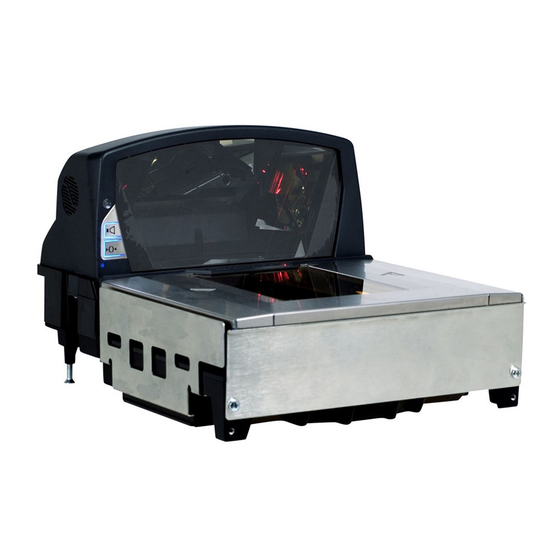
Page 15: Ms2422 Components
MS2422 Components Figure 10. MS2422 Components Item No. Description of Item Volume/Tone Multi-Function Button (see page 42) Blue LED Indicators (see page 35) Speaker (see page 35) Finger Recesses for Lifting (Located Under Platter) High Impact Window Frame / Vertical Window (Laser Aperture) Replaceable Stainless Steel Platter with Diamonex or Sapphire Horizontal Window (Laser Aperture) Flow Direction Indicator... -
Page 16: Ms2422 Dimensions
MS2422 Dimensions Figure 11. MS2422 Dimensions MS2422 Connector Panel Figure 12. MS2422 Connectors Specifications are subject to change without notice. -
Page 17: Ms2422 Caution And Serial Number Labels
MS2422 Caution and Serial Number Labels Figure 13. MS2422 Label Locations (Top) and Examples (Bottom) Caution: To maintain compliance with applicable standards, all circuits connected to the imager must meet the requirements for SELV (Safety Extra Low Voltage) according to EN/IEC 60950-1. To maintain compliance with standard CSA C22.2 No. -
Page 19: Installation
Installation Quick Installation Outline The following is a quick preview of the steps required for first time installations. Each item is discussed in detail later in this section. Determine clearance, ventilation, and service access requirements. Determine checkout counter layout taking into account package flow, cable routing, and power requirements. -
Page 20: Power Installation
Site Requirements Power Installation The Power Supply (AC/DC) should be connected to an AC Outlet that is free of electrical noise (clean). A qualified electrician can determine the amount of electrical noise on the AC line. See additional information on power installation and restrictions under the Installation: Interface section of this manual. Note: Using a switched AC outlet is recommended. -
Page 21: Unpacking The Unit
Unpacking the Unit 1. Make sure the shipping box is topside up before opening. 2. Remove the accessories box and check the box’s content for the following items. Product Manuals Power Supply Communication Cables Remote Scale Display (Optional) Figure 14 3. -
Page 22: Installing The Unit In The Counter
Installing the Unit in the Counter MS2421 Mounting Diagram Figure 17. MS2421 Mounting Diagram Specifications are subject to change without notice. -
Page 23: Ms2422 Mounting Diagram
Installing the Unit in the Counter MS2422 Mounting Diagram Figure 18. MS2422 Mounting Diagram Specifications are subject to change without notice. -
Page 24: Ms2431 Mounting Diagram (Two Point Support)
Installing the Unit in the Counter MS2431 Mounting Diagram (Two Point Support) Figure 19. MS2431 Mounting Diagram, Two Point Support Specifications are subject to change without notice. -
Page 25: Ms2431 Mounting Diagram (Three Point Support)
Installing the Unit in the Counter MS2431 Mounting Diagram (Three Point Support) Figure 20. MS2431 Mounting Diagram, Three Point Support Specifications are subject to change without notice. -
Page 26: Cable Installation (Interface Specific)
Cable Installation (Interface Specific) RS232 The following steps describe how to properly install the cables for an RS232 application. The scanner must then be configured to match the host’s RS232 parameters. Cable installation alone does not guarantee that the scanner will communicate properly with the host system. Note: Configuration bar codes are located in the MetroSelect Configuration Guide (PN 00-02407x) and the MS2xxx Stratos Series Configuration Addendum (PN 00-02034x). - Page 27 Cable Installation (Interface Specific) RS232 xx** Specifies international connection. See the Base Kit Components and Optional Accessories section of this guide for a complete listing. See power source caution statement on pages 10 or 13 of this manual. Figure 21. RS232 Interface Cable Installation Schematic...
-
Page 28: Full Speed Usb
Cable Installation (Interface Specific) Full Speed USB The following steps describe how to properly install the cables for a Full Speed USB scanner application. The scanner must then be configured to match the host’s USB parameters. Cable installation alone does not guarantee that the scanner will communicate properly with the host system. -
Page 29: Usb Serial Emulation Mode
Cable Installation (Interface Specific) Full Speed USB Step 8 is for USB Serial Emulation Mode or Keyboard Emulation Mode only. 8. Configure the scanner for USB Serial Emulation Mode or USB Keyboard Emulation Mode by scanning the appropriate configuration bar codes in the USB section of the MetroSelect Configuration Guide (PN 00-02407x) under Low Speed USB. -
Page 30: Rs485
Cable Installation (Interface Specific) RS485 The following steps describe how to properly install the cables for an RS485 scanner application. The scanner must then be configured to match the host’s RS485 parameters. Cable installation alone does not guarantee that the scanner will communicate properly with the host system. Note: Configuration bar codes are located in the MetroSelect Configuration Guide (PN 00-02407x) and the MS2xxx Stratos Series Configuration Addendum (PN 00-02034x). - Page 31 Cable Installation (Interface Specific) RS485 xx** Specifies international connection. See the Base Kit Components and Optional Accessories section of this guide for a complete listing. See power source caution statement on pages 10 or 13 of this manual. Figure 23. RS485 Cable Installation Schematic...
-
Page 32: Cable Installation (Secondary Honeywell Scanner)
Cable Installation (Secondary Honeywell Scanner) The following steps describe how to properly install the cables between a secondary Honeywell scanner and the MS2421/MS2422/MS2431 scanner. The MS2421/MS2422/MS2431 and the secondary scanner must then be configured to communicate properly. Cable installation alone does not guarantee that the MS2421/MS2422/MS2431 scanner will communicate properly with the host system and secondary scanner. - Page 33 Cable Installation (Secondary Honeywell Scanner) † See Aux power notes on page 28 See power source caution statement on pages 10 or 13 of this manual. Figure 24. Secondary Scanner Cable Installation Schematic...
-
Page 34: Eas Deactivation
EAS Deactivation SW1 and SW2 are the switch banks inside the Checkpoint device that set the deactivation range. The following is a list of Checkpoint recommended switch bank settings. Base Model Checkpoint Recommended Switch Bank Settings MS2421 SW1 & SW2 switches 1 and 6 set to ON MS2422 SW1 &... -
Page 35: Scanner Operation
Scanner Operation Scan Zone Figure 27. Checker-Side (13 mil) Figure 28. Horizontal Left/Right (13 mil) Specifications are subject to change without notice. Typical scan zones shown. - Page 36 Scan Zone Figure 29. Horizontal Direct (13 mil) Figure 30. Vertical Direct (13 mil) Specifications are subject to change without notice. Typical Scan Zones shown.
-
Page 37: Wake Activation Area (Photocell Led Output)
Wake Activation Area (Photocell LED Output) † The MS2421/MS2422/MS2431 scanner’s default power save mode is Dual Action Power Save Mode #2 (see page 41). This power save mode turns the laser OFF after a configured period of non-use then turns the motor OFF after thirty-minute intervals. -
Page 38: Changing The Wake Area Sensitivity Level
Wake Activation Area Sensitivity (Photocell LED Output Range) Changing the Wake Area Sensitivity Level (Photocell LED Range Adjust) The MS2400 Series bar code scanner wake area sensitivity level can be set to the end users preference by scanning one of the Photocell Sensitivity adjustment bar codes below. *Max Photocell Sensitivity This feature enables the MS24xx to... -
Page 39: Audible Indicators
Audible Indicators When in operation, the MS2421/MS2422/MS2431 scanner provides audible feedback that indicates the status of the unit and the current scan. Eight settings are available for the tone of the beep (normal, six alternate tones and no tone) plus three volume settings. To change the tone or volume, refer to the Changing the Beeper Tone and Volume section of this manual. -
Page 40: Visual Indicators
Visual Indicators Blue LED is located near the bottom corner of the vertical output window. When the scanner is ON, the flashing or constant illumination of the LED indicates the status of the scanner and the current scan. No Blue LED The blue LED will not be illuminated if the scanner is not receiving power from the host or transformer. -
Page 41: Failure Modes
Failure Modes Flashing Blue and One Razzberry Tone This indicates that the scanner has experienced a laser subsystem failure. The scanner will try up to three times to correct the failure condition. If the laser subsystem continues to fail, that subsystem (horizontal or vertical) will be shut down and an error indication will be shown on the Diagnostic Indicator Display. -
Page 42: Diagnostic Indicator Display; Error Codes
Diagnostic Indicator Display There is a two-digit error code display located under horizontal output window near the top of the platter (see figure below). Figure 33. Error Code Display The following is a list of possible error codes and their meanings. Some errors will require immediate scanner maintenance. - Page 43 Error Description Code COPROCESSOR COMMUNICATION ERROR – The main microprocessor is not communicating with the interface coprocessor. The interface coprocessor may be in a fault condition with the host or just not able to respond. This error may appear when the scanner is configured for USB or RS485 interface applications or during an attempt to update the interface software through the flash utility.
- Page 44 Error Description Code LASER #2 (RIGHT HORIZONTAL) UNDERCURRENT WARNING – The laser in the right horizontal scanning subsystem is drawing too little current. The laser is probably not on. This could be the result of a loss of the required set point in memory. Have the unit checked at an authorized service center.
-
Page 45: Power Save Modes
Power Save Modes The MS2421/MS2422/MS2431 bar code scanners have five configurable power save modes. Refer to the MetroSelect Configuration Guide for additional information on Power Save Modes. 1. Blink Power Save Mode: Blinks the laser OFF & ON after a configured period of non-use. When the scanner recognizes a bar code it will exit the Blink mode. -
Page 46: Beeper Options And Button Functions
Beeper Options and Button Functions Changing the Beeper Tone Beeper tones may be configured incrementally using the following bar code. The new tone will be heard followed by a short pause. Two more new tones will be heard signifying the new setting has been stored in memory. -
Page 47: Startup
Startup When the scanner first receives power, the blue LED will turn on and the scanner will beep once. The scanner is now ready to scan. Power-Up Test Mode When a MS2421/MS2422/MS2431 scanner is first powered up, it cycles through a number of self-tests before starting normal operation. -
Page 49: Maintenance
Maintenance Horizontal Scan Window Replacement Note: After the replacement platter has been installed, remove all protective film from the new platter’s window. The unit will not function properly if the protective film is not removed. Figure 38. Platter/Horizontal Scan Window Replacement See replacement parts on page 3. -
Page 50: Daily Maintenance
Daily Maintenance Smudges and dirt on the unit’s window can interfere with the unit’s performance. If the horizontal or vertical output windows require cleaning, use only a mild glass cleaner containing no ammonia. When cleaning the window, spray the cleaner onto a lint free, non-abrasive cleaning cloth then gently wipe the window clean. -
Page 51: Troubleshooting
Troubleshooting The following guide is for reference purposes only. Contact a customer service representative to preserve the limited warranty terms. Symptom Possible Cause(s) Solution All Interfaces Check the transformer, outlet, and the power strip. No LED, beep, or No power is being supplied Make sure the power cable is plugged into the motor spin. - Page 52 Symptom Possible Cause(s) Solution All Interfaces The print quality of the bar code is suspect. Scanner beeps at The type of printer and/or the printer settings could be some bar codes and the problem. Check the character NOT for others of the length lock.
- Page 53 The auxiliary input port’s data format must match the main output format of the secondary scanner. * Refer to the MS2xxx Stratos Series Configuration Addendum (PN 00-02034x) under Scanner Configuration Bar Codes: Auxiliary Port, Quick Start for a Secondary Honeywell Scanner.
-
Page 55: Scanner And Cable Terminations
Scanner and Cable Terminations Scanner Pinout Connections The MS2421/MS2422/MS2431 scanner terminates to 10-pin modular jacks located on the bottom of the unit. The serial number label indicates the model number and interface of the scanner. DC Power Function Function EAS In No Connect EAS Out Earth Ground... - Page 56 Scale Ready MS2421/MS2431 Models – Additional Pinout Connections There are four additional 10-pin modular jacks located on the bottom of the of the MS2421/MS2431 scanner models that may be used for an integrated scale application and the use of a remote display. Note: Please keep in mind that every application is unique.
-
Page 57: Cable Connector Configurations
Cable Connector Configurations The following cables are examples of some of the standard cables that may be shipped with the MS2421/MS2422/MS2431 bar code scanner. Please keep in mind that every application is unique and the cables received with the MS2421/MS2422/MS2431 scanner may be custom cables that are not shown below. - Page 58 Cable Connector Configurations Aux Port Configuration Cable*, PN 57-57008x-N-3 Function** No Connect Output from Scanner Input to Scanner No Connect Ground No Connect 9-Pin D-Type Connector No Connect No Connect No Connect RS232 LSO/AUX Cable, PN 57-57099x-3 † Function Signal Ground RS232 from Aux / Secondary Scanner RS232 to Aux / Secondary Scanner RTS from Aux / Secondary Scanner...
-
Page 59: Regulatory Compliance
Regulatory Compliance Safety ITE Equipment IEC 60950-1, EN 60950-1 Laser Laser Class 1: IEC 60825-1:1993+A1+A2, EN 60825-1:1994+A1+A2 Caution Use of controls or adjustments or performance of procedures other than those specified herein may result in hazardous laser light exposure. Under no circumstances should the customer attempt to service the laser scanner. -
Page 60: Emc
Emissions FCC Part 15, ICES-003, CISPR 22, EN 55022 Immunity CISPR 24, EN 55024 Note: Immunity performance is not guaranteed for scanner cables greater than 3 meters in length when fully extended. Changes or modifications not expressly approved by the party responsible for compliance could void the user’s authority to operate the equipment. - Page 61 Standard Europeo Attenzione Questo e’ un prodotto di classe A. Se usato in vicinanza di residenze private potrebbe causare interferenze radio che potrebbero richiedere all’utilizzatore opportune misure. Attention Ce produit est de classe “A”. Dans un environnement domestique, ce produit peut être la cause d’interférences radio.
-
Page 63: Limited Warranty
Limited Warranty Honeywell International Inc. ("HII") warrants its products and optional accessories to be free from defects in materials and workmanship and to conform to HII’s published specifications applicable to the products purchased at the time of shipment. This warranty does not cover any HII product which is (i) improperly installed or used;... -
Page 65: Patents
Patents This Honeywell product may be covered by, but not limited to, one or more of the following US Patents: U.S. Patent No.; 5,216,232; 5,343,027; 5,686,717; 5,777,315; 5,828,049; 6,299,065; 6,347,743; 6,354,505; 6,422,467; 6,481,625; 6,494,377; 6,814,292; 6,830,190; 6,874,690; 6,918,540; 6,945,463; 6,951,304; 6,969,004;... -
Page 67: Index
Index flow ..............7, 11 frame ..............11 AC ............see power function ..........47, 51–54 application............38 audible ..........see indicators AUX ............7, 49, 51 ground ............51–54 beep........... see indicators host ..........35, 36, 43, 47–50 blue LED ..........see indicators button indicators .............5 multi-function........... - Page 68 storage..............5 switch..............30 razzberry tone.......... 35, 36, 37 regulatory compliance........55–56 repair..........37, 38, 39, 40, 59 test..............43 RMA..............59 tone............ 7, 11, 35, 42 transformer ........... see power troubleshooting ..........47–50 safety ............. 56, 57 scale ..............52 scan pattern ............5 ventilation ............5, 15 scan speed ............
-
Page 69: Customer Support
Customer Support Technical Assistance If you need assistance installing or troubleshooting your device, please call your distributor or the nearest technical support office: North America/Canada Telephone: (800) 782-4263 E-mail: hsmnasupport@honeywell.com Latin America Telephone: (803) 835-8000 Telephone: (800) 782-4263 E-mail: hsmlasupport@honeywell.com Brazil... -
Page 70: Product Service And Repair
Product Service and Repair Honeywell International Inc. provides service for all its products through service centers throughout the world. To obtain warranty or non-warranty service, contact the appropriate location below to obtain a Return Material Authorization number (RMA #) before returning the product. - Page 72 Honeywell Scanning & Mobility 9680 Old Bailes Road Fort Mill, SC 29707 www.honeywellaidc.com 00-05311 Rev C February 2010...