Table of Contents
Advertisement
Advertisement
Table of Contents

Related Manuals for Honeywell MK7580-30B41-00 - Metrologic MS7580 Genesis


Summary of Contents for Honeywell MK7580-30B41-00 - Metrologic MS7580 Genesis
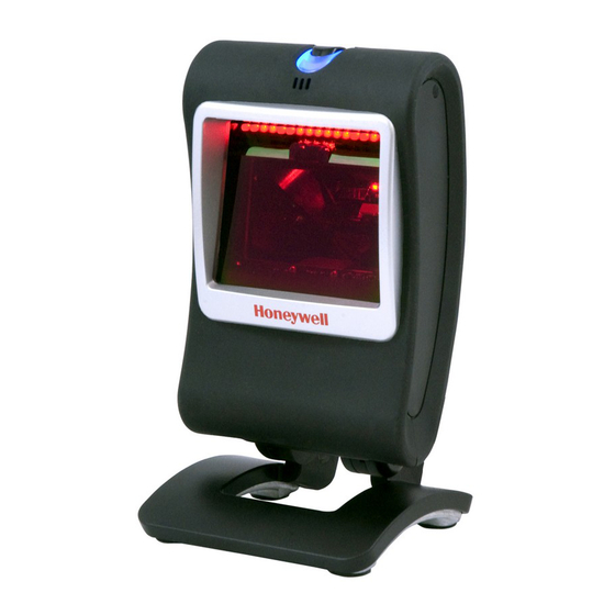
- Page 1 ™ Genesis 7580 Presentation Area Imager User’s Guide...
- Page 2 Disclaimer Honeywell International Inc. (“HII”) reserves the right to make changes in specifications and other information contained in this document without prior notice, and the reader should in all cases consult HII to determine whether any such changes have been made. The information in this publication does not represent a commitment on the part of HII.
-
Page 3: Table Of Contents
Table of Contents Introduction Product Overview ..................... 1 Base Kit Components ..................2 Optional Accessories ..................2 MS7580 Components ..................4 Labels ....................... 5 Maintenance ..................... 5 Cable Installation and Removal ................ 6 Interface Installation RS232 ......................7 Keyboard Wedge ....................8 RS485 ...................... - Page 4 Troubleshooting Guide ................. 29 Design Specifications ................33 Applications and Protocols ..............35 Configuration and Upgrades ..............37 Configuration Modes ..................37 Upgrading the Firmware ................. 37 MS7580-124-EAS Model Integrated RF EAS Antenna Connection ............39 EAS System Connection ................40 Configuration for EAS Applications ..............
-
Page 5: Introduction
PDF, 2D or OCR fonts without proper limited use licenses provided by Honeywell. If you wish to purchase a limited license for one or more of the key features not included in the standard imager, please specify at the time of sale or otherwise contact a customer service representative for more information. -
Page 6: Base Kit Components
Base Kit Components Part # Description MS7580-124 Genesis 7580 Presentation Area Imager ® 00-02544 MetroSelect Single-Line Configuration Guide 00-05252 Area-Imaging Supplemental Configuration Guide* GEN-7580-UG Genesis 7580 Installation and User’s Guide* EAS equipped models are indicated with an EAS extension on the model number (i.e., MS7580-124-EAS). - Page 7 Part # Description Cable Compatibility Warning The MS7580 requires a cable designed for a 12VDC area imager. Do not attempt to use any cables other than the specified cables listed below (cable series 5S-5Sxxx). Any damage incurred from incorrect cable usage will void the limited warranty shown on page 53.
-
Page 8: Ms7580 Components
MS7580 Components Item Item Description Blue and White LED See Visual Indicators (on page 20) Button Mode Select Button See Audible Indicators (on page 19) Speaker Window LED Aperture Adjustable Base 10-pin RJ45, Female Socket, Cable Connection See Imager Pinout Connections (on page 49) Cable Release See Cable Installation and Removal (on page 6) Note: The MS7580-124-EAS model is equipped with an integrated antenna... -
Page 9: Labels
Labels Each MS7580 has a label located near the top of the output window. This label provides the imager’s model number, date of manufacture, serial number, CE and caution information. Additional information has been molded into the underside of the imager's case. The following figure gives an example of the label and the molded text with their locations identified. -
Page 10: Cable Installation And Removal
Cable Installation and Removal Installation Insert the cable’s modular connector into the socket on the imager. Pull gently on the cable strain relief to ensure the cable is installed. Note: If the cable is not fully latched, the imager may power intermittently. Figure 3. -
Page 11: Interface Installation
In addition, please check that the imager and host system are using the same communication protocol. The MS7580 requires 12V power to function for RS232 operation. Honeywell recommends using the external power supply shipped with the MS7580. -
Page 12: Keyboard Wedge
Keyboard Wedge Turn off power to the host device. Plug the interface cable’s modular connector into the socket on the imager. Disconnect the keyboard from the host device. Connect the “Y” ends of the communication cable to the keyboard and the keyboard port on the host device. -
Page 13: Rs485
RS485 Turn off power to the host device. Plug the interface cable’s modular connector into the socket on the imager. Connect the other end of the cable to proper COM port of the host device Turn on power to the host device. The MS7580 will start to initialize. -
Page 14: Usb
Turn off power to the host device. Plug the interface cable’s modular connector into the socket on the imager. Plug the USB end of the cable into the host’s USB port. Steps 4–6 are for VLink cables with a built in power jack and 12V external power supply. - Page 15 • For information on configuring the MS7580 for USB Serial Emulation Mode or IBM OEM, refer to the USB section of the MetroSelect Single-Line Configuration Guide (PN 00-02544). • Plugging the imager into a port on the host device does not guarantee that scanned information will be communicated properly to the host device.
-
Page 17: Mounting The Ms7580
Mounting the MS7580 Components of Adapter Kit 46-00911 Item Item Description Qty. Adapter Plate Locking Plate Base Cover M3 x .5 - 10 mm Flat Head Phillips Screw M3 x .5 - 8 mm Flat Head Phillips Screw #7 x 1.00 in. FHP Wood Screw MS7580 Wall Mount Installation Guide Figure 9. -
Page 18: Installation Of Adapter Kit 46-00911
Installation of Adapter Kit 46-00911 Remove the rubber feet on the bottom of the MS7580. Attach the adapter plate to the bottom of the imager with the four M3 x .5 x 10 mm screws ( ) provided in the kit. Attach the base plate to the adapter plate with the four M3 x .5 x 8 mm screws ( ... - Page 19 Use the locking plate as a guide to drill three #39 pilot holes (A) in the mounting surface. Figure 13. Locking Plate (Not Drawn to Scale) Secure the locking plate to the wall with the three #7 wood screws () provided in the kit.
-
Page 20: Installation Of Wall Mount Kit 46-00913
Installation of Wall Mount Kit 46-00913 Drill two #39 pilot holes in the mounting surface. The pilot holes should be centered vertically 44 mm apart. Position the wall mount over the pilot holes with the arrow pointing up. Secure the wall mount to the wall with the two #7 wood screws () provided in the kit. -
Page 21: Operation
Operation Modes of Operation The MS7580 supports two standard modes of operation for scanning bar codes, automatic activation and manual activation scanning. Scanning while in the automatic activation mode can occur in either one of two configurable options, pass-through or presentation. - Page 22 Note: Decoding and functional capability of the imager is restricted through the use of license numbers provided by Honeywell. Imagers will not support key features such as, but not limited to, the ability to decode PDF, 2D or OCR fonts without proper licenses.
-
Page 23: Audible Indicators
Audible Indicators The MS7580 provides audible feedback during operation. The audible feedback indicates the status of the imager. Eight settings are available for the tone of the beep (normal, 6 alternate tones and no tone). To change the tone, refer to the MetroSelect Single-Line Configuration Guide, PN 00-02544 or MetroSet2’s help files. -
Page 24: Visual Indicators
Visual Indicators The imager has blue and white LED indicators surrounding the button on the top of the imager. When the imager is on, the intensity of the LED and the flashing or stationary activity of the LEDs, indicates the status of the current scan and the diagnostic imager. -
Page 25: Failure Modes
Failure Modes Long Razzberry Tone – During Power Up Failed to initialize or configure the imager. If the imager does not respond after reconfiguration, return the imager for repair. Short Razzberry Tone – During Scanning An Invalid bar code has been scanned when in configuration mode. -
Page 26: Field Of View
Field of View Figure 20. Field of View... -
Page 27: Depth Of Field By Minimum Bar Code Element Width
PDF, 2D or OCR fonts without proper limited use licenses provided by Honeywell. If you wish to purchase a limited license for one or more of the key features not included in the standard imager, please specify at the time of sale or otherwise contact a customer service representative for more information. -
Page 28: Ir Activation Range
IR Activation Range The MS7580 has a built in object detection sensor that instantly turns on the imager when an object is presented within the imager’s IR Activation Area, shown below. Figure 22. IR Activation Area... -
Page 29: Illumination Source
Illumination Source Figure 23. Illumination Source... -
Page 30: Ir Source
IR Source Figure 24. IR Source... -
Page 31: Targeting Source
Targeting Source Figure 25. Targeting Source... -
Page 33: Troubleshooting Guide
Troubleshooting Guide The following troubleshooting guide is for reference purposes only. Contact a customer service representative or technical support representative to preserve the limited warranty terms. See page 61 for contact information. All Interfaces Symptoms Possible Causes Solution No power is being Check transformer, outlet, and supplied to the power strip. - Page 34 Symptoms Possible Causes Solution The imager powers up, but The beeper is Enable the beeper and select a does not beep disabled and no tone tone. when bar code is is selected. scanned. UPC/EAN, Code 39, interleaved 2 The imager The bar code of 5, Code 93, Code 128, Codabar powers up, but...
- Page 35 Symptoms Possible Causes Solution The bar code may Check if it is a check have been printed digit/character/or border problem. incorrectly. The imager The imager is not beeps at some configured correctly Check if check digits are set bar codes and for this type of bar properly.
- Page 36 Symptoms Possible Causes Solution The imager The imager and host Check that the imager and the scans but the may not be configured host are configured for the same data is not for the same interface interface parameters. correct. parameters. The following item is only relevant for an RS232 interface.
-
Page 37: Design Specifications
Design Specifications Operational Light Source: LED 645 nm ±7.5 nm Pulse Duration: Up to 600µs (Default) Maximum Output Maximum 70 mA emits 5800 mlm of the LED: Depth of Scan Field: 0 mm – 158 mm (0" – 6.2") for 0.33 mm (13 mil) 51 mm x 31 mm (2.0"... - Page 38 Mechanical Height (H): 150 mm (5.91") Width (W): 83 mm (3.27") Depth (D): 80 mm (3.15") 340 g ± 15 g Weight: (12 oz. ± 5 oz.) Termination: 10 pin modular RJ45 Electrical +12 Volt +5 Volt Adapter Value USB Power Value Input Voltage: 12VDC ±...
-
Page 39: Applications And Protocols
The MS7580 with a built-in PC Keyboard Wedge interface is designed for Keyboard emulation use only. Many RS232 configurable functions, available in other Honeywell imagers, are also available as keyboard wedge functions. The following are the most important selectable options specific to the keyboard wedge. -
Page 41: Configuration And Upgrades
MetroSelect Single-Line Configuration Guide. Upgrading the Firmware The MS7580 is part of Honeywell’s line of imagers with flash upgradeable firmware. The upgrade process requires, a new firmware file supplied to the ... - Page 42 To upgrade the firmware in the MS7580: Plug the imager into a serial communication port on the host system. Start the MetroSet2 software. Click on the plus sign (+) next to POS Scanners to expand the supported imager list. Choose the MS7580 Genesis from the list. Click on the Configure Genesis/7580 Scanner button.
-
Page 43: Ms7580-124-Eas Model
MS7580-124-EAS Model MS7580-124-EAS models are equipped with an integrated antenna for Electronic Article Surveillance (EAS) system support. The following information should be used in conjunction with the manufacturer’s EAS system documentation for successful integration of an MS7580-124-EAS Genesis. Integrated RF EAS Antenna Connection The following information is applicable for MS7580-124-EAS kits containing an RS232, MX-5S114-E-3 cable or a USB, MX-5S236-E-3 cable. -
Page 44: Eas System Connection
The following information should be used in conjunction with the manufacturer’s documentation EAS system. ® Checkpoint EAS System Integration Honeywell cables compatible with Checkpoint EAS systems include five additional wires for device connection*. Consult the table below for the appropriate wire and terminal configuration. † Antenna and Interlock... - Page 45 Inside the Checkpoint device, two switch banks set the deactivation antenna tuning. The recommended settings for the switch banks are shown below. See page 44 for tag deactivation guidelines. Switch Bank Settings Switches 1 - 6 Switches 1 - 6 Settings of 0pF to 47pF are recommended to achieve a maximum deactivation range.
-
Page 46: Configuration For Eas Applications
Configuration for EAS Applications EAS support is disabled by default in the MS7580-124-EAS series. To enable EAS support the imager must be configured for a system type and signal mode. Follow the configuration sequence below to configure the imager for EAS functionality. - Page 47 Scan the desired EAS timeout length (applicable for regular mode only). The EAS timeout length specifies the maximum time that the area imager will leave the EAS interlock signal asserted following a successful scan. The EAS timeout setting has no effect in continuous mode. Note: If the area imager routinely fails to deactivate EAS tags, increase the value of the timeout setting.
-
Page 48: Eas Tag Deactivation Range
EAS Tag Deactivation Range Antenna Precaution The integrated EAS antenna is built into the stand/base of the imager. Do not enclose or rest the imager’s base in close proximity to dense metal. The metal may interfere with the antenna decreasing the expected deactivation range. Tag Storage Precaution Do not store tags within 45.7 cm [18.0″] of the MS7580. - Page 49 Figure 28. Expected Tag Deactivation Area (Top View)
-
Page 50: Imager Pinouts-Ms7580-124-Eas
Imager Pinouts–MS7580-124-EAS Figure 29. MS7580-124-EAS, 10-Pin Female Modular Socket RS232 Function Function Signal/Power Ground Signal/Power Ground CTS Input Tied to Pin 4 in Cable RS232 Receive Input No Connect No Connect Tied to Pin 2 in Cable Reserved Reserved RTS Output ... -
Page 51: Cable Pinouts
‡ Cable Pinouts (Host End) RS232, 12V VLink Cable MX-5S114-E-3 Function Shield Ground RS232 Receive Output RS232 Transmit Input Power/Signal Ground Figure 31. 9-Pin Female, D-Type Host +12VDC MX-5S236-E-3 Function PC +5V/V_USB Figure 32. USB Type A, Non-Locking Ground Antenna Disconnect Press the release lock on the cable’s EAS connector. -
Page 53: Imager And Cable Terminations
Imager and Cable Terminations ‡ Standard Imager Pinouts Figure 34. Back/Connector View of the MS7580 RS232 Keyboard Wedge Function Function Signal/Power Ground Signal/Power Ground CTS/DTR Input Tied to Pin 3 in Cable RS232 Receive Input Tied to Pin 2 in Cable No Connect PC Data No Connect... -
Page 54: Standard Cable Pinouts
‡ Standard Cable Pinouts (Host End) RS232, 12V VLink Cable 5S-5S000-3 Function Shield Ground RS232 Transmit Output RS232 Receive Input No Connect Power/Signal Ground Reserved CTS Input 9-Pin Female, D-Type RTS Output +12VDC RS485 MX-RS485-5S006-3 Function Signal/Power Ground IBM A+ IBM B- SDL A Key Connector +12VDC... - Page 55 PC Clock No Connect Honeywell will supply an adapter cable with a 5-pin DIN male connector on one end and a 6-pin mini DIN female connector on the other. According to the termination required, connect the appropriate end of the adapter cable to the VLink cable, leaving the necessary termination exposed for connecting to the keyboard and the keyboard port on the PC.
-
Page 57: Limited Warranty
Limited Warranty Honeywell International Inc. ("HII") warrants its products and optional accessories to be free from defects in materials and workmanship and to conform to HII’s published specifications applicable to the products purchased at the time of shipment. This warranty does not cover any HII product which is (i) improperly installed or used;... - Page 58 All provisions of this Limited Warranty are separate and severable, which means that if any provision is held invalid and unenforceable, such determination shall not affect the validity of enforceability of the other provisions hereof. Use of any peripherals not provided by the manufacturer may result in damage not covered by this warranty.
-
Page 59: Regulatory Compliance
Regulatory Compliance Safety ITE Equipment IEC 60950-1:2005, EN 60950-1:2006+A11:2009 LEDs have been tested and classified as “EXEMPT RISK GROUP” to the standard: IEC 62471:2006. Caution Use of controls or adjustments or performance of procedures other than those specified herein may result in hazardous radiation exposure. Under no circumstances should the customer attempt to service the LED scanner. -
Page 60: Emc
emittierender Diodenstrahl, selbst wenn Sie glauben, daß der Scanner nicht aktiv ist. Öffnen Sie niemals den Scanner, um in das Gerät hineinzusehen. Wenn Sie dies tun, können Sie sich einer gefährlichen Licht emittierender Diodenstrahlung aussetzen. Der Einsatz optischer Geräte mit dieser Laserausrüstung erhöht das Risiko einer Sehschädigung. -
Page 61: European Standard
This device complies with part 15 of the FCC Rules. Operation is subject to the following two conditions: (1) This device may not cause harmful interference, and (2) this device must accept any interference received, including interference that may cause undesired operation. Notice This Class A digital apparatus complies with Canadian ICES-003. -
Page 62: Class B Devices
Changes or modifications not expressly approved by the party responsible for compliance could void the user’s authority to operate the equipment. Class B Devices The following is applicable when the scanner cable is less than 3 meters (9.8 feet) in length when fully extended: Les instructions ci-dessous s’appliquent aux cables de scanner ne dépassant pas 3 métres (9.8 pieds) de long en extension maximale: Folgendes trifft zu, wenn das Scannerkabel kürzer als 3 Meter ist:... -
Page 63: Index
Index AC ......... 2, 7–11, 30 Field of View ....... 22 Accessories ........2 Firmware ........34 Adapter ......2, 13, 14, 45 Flash ROM ........34 Aperture......... 4 Audible Indicator ....20–21, 34 Automatic Activation Mode ..17 Host ........7–11 Bar Code ..... - Page 64 Swiftdecoder™ ......1 Pass-Through ......17 Pinouts ......43, 44–45 Tone ........20–21 Power ......7–11, 30, 34 Transformer ....2, 7–11, 30 Power Supply ...... 6, 7–11 Troubleshooting ....25–28 Presentation ........ 17 Protocols ........31 UL ........5, 7–11 Upgrade ........
-
Page 65: Customer Support
E-mail: hsmlasupport@honeywell.com Brazil Telephone: +55 (11) 5185-8222 Fax: +55 (11) 5185-8225 E-mail: brsuporte@honeywell.com Mexico Telephone: 01-800-HONEYWELL (01-800-466-3993) E-mail: soporte.hsm@honeywell.com Europe, Middle East, and Africa Telephone: +31 (0) 40 7999 393 Fax: +31 (0) 40 2425 672 E-mail: hsmeurosupport@honeywell.com Hong Kong... -
Page 66: Product Service And Repair
Product Service and Repair Honeywell International Inc. provides service for all its products through service centers throughout the world. To obtain warranty or non-warranty service, contact the appropriate location below to obtain a Return Material Authorization number (RMA #) before returning the product. - Page 68 Honeywell Scanning & Mobility 9680 Old Bailes Road Fort Mill, SC 29707 www.honeywellaidc.com GEN-7580-UG Rev C 10/11...