Table of Contents
Advertisement
Quick Links
Advertisement
Table of Contents

Related Manuals for Ryobi Airwave RA-C2550-G


Summary of Contents for Ryobi Airwave RA-C2550-G
- Page 1 RA-c2550 AIRwAve 50L 2.0HP dIRect dRIven AIR comPRessoR oPeRAtoR's mAnUAL oRIgInAL InstRUctIons Important! It is essential you read the instructions in this manual before starting and operating this machine. Subject to technical modifications.
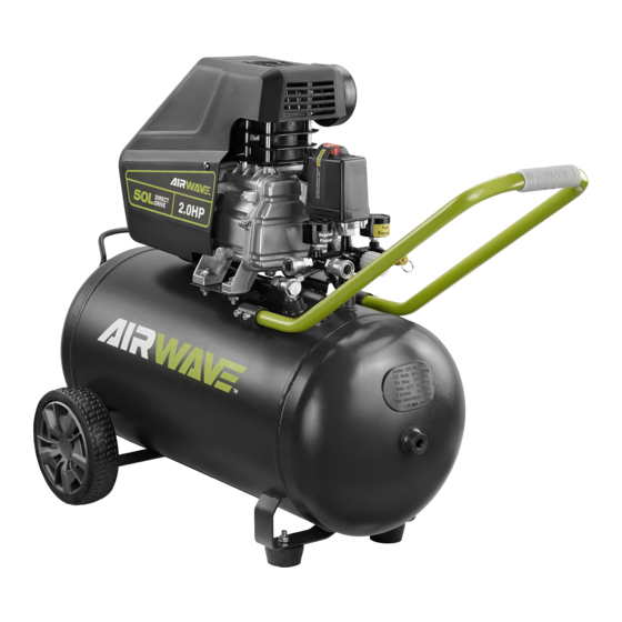
- Page 2 descRIPtIon 1. Air filter assembly 19. Axle bolt 2. On/off switch 20. Oil fill hole cap 3. Tank pressure gauge 21. Sight glass 4. Pressure relief valve 22. Red dot 5. Front handle 23. Quick connect air fitting 6. Pressure regulator knob 24.
- Page 3 Fig. 2 Fig. 3 Fig. 4 Fig. 5 Fig. 6...
- Page 4 Fig. 7 Fig. 8a Fig. 8b Fig. 9 Fig. 10 Fig. 12 Fig. 11...
- Page 5 Fig. 13 Fig. 14 Fig. 15 Fig. 16 16 33...
- Page 6 Fig. 17...
-
Page 7: General Safety Warnings
operation is dusty. geneRAL sAfety wARnIngs ■ Protect your hearing. Wear hearing protection during extended periods of operation. wARnIng ■ Do not overreach. Keep proper footing and balance at all times. Read and understand all instructions. Failure to follow all instructions listed below, may result in electric shock, ■... - Page 8 not be used for a while, it is best to leave drain valve A respirator may be necessary in dusty environments open until such time as it is to be used. This will allow or when spraying paint. Do not carry while painting. moisture to completely drain out and help prevent ■...
-
Page 9: Product Specifications
wARnIng PRodUct sPecIfIcAtIons Do not use this product if any parts on the packing Rated motor power 1500 W list are already assembled to your product when you unpack it. Parts on this list are not assembled to the Rated current product by the manufacturer and require customer Air outlets 2 pcs, 6.35mm (1/4”) -
Page 10: Installing Feet
key. Make sure the handle is securely fixed. of the oil does not exceed the top of the red dot at sight glass. InstALLIng feet 3. Tighten the cap securely into the oil fill hole. See figure 4. Replace the oil after the first 10 hours of operation and 1. -
Page 11: Draining The Tank
step at a time. wARnIng 3. Use care in transporting the unit down or up stairs Always ensure the switch is in the OFF (O) position to avoid damage to the stairs, damage to unit and and the regulator pressure gauge reads zero before personal injury. -
Page 12: Reset Button
2. Pull the ring on the pressure relief valve to release until to reset the air compressor: pressure gauge reads less than 1.4 bar. 1. Unplug the air compressor. 3. Release the ring. 2. Turn the air compressor off. 4. Rotate drain valve counterclockwise to open and drain 3. -
Page 13: General Maintenance
The sight glass indicates the oil level and lets the operator wARnIng check if oil should be added. Always wear eye protection with side shields. Failure 1. Place a suitable container underneath the drain to to do so could result in objects being thrown into your collect used oil. - Page 14 Wet condition alert. Do not expose to rain. Store indoors. Risk of bursting. Do not adjust regulator to result in output pressure greater than marked maximum pressure of attachment. Do not use at pressure greater than 8 bar. Risk of fire or explosion. Spray area must be well ventilated.
-
Page 15: Troubleshooting
tRoUBLesHootIng PRoBLem cAUse PossIBLe soLUtIon Compressor will not run Loss of power or overheating Check for proper use of extension cord No electrical power Check to be sure unit is plugged in Check fuse/breaker Blown shop/house fuse Replace shop/house blown fuse Shop/house breaker open Reset shop/house breaker, determining why problem happened... - Page 16 PRoBLem cAUse PossIBLe soLUtIon Compressor runs continuously Defective pressure switch Take compressor to service centre Excessive air usage Take compressor to service centre Decrease air usage; compressor not large enough for tool’s requirement Piston rings are worn Replace piston rings; inlet filter is blocked, call customer service for...
-
Page 17: Parts List
PARts LIst... - Page 18 Description Description Description Description Crankcase Valve assembly Bearing 6202 Unloading pipe Crank web Head gasket Stator Wheel bolt M10 x 56 Hex socket bolt, Cylinder head Rotor Wheel 7" M8 x 22, LH Connecting rod Flat washer 8 Bearing 6203 Flat washer 10 Gasket Spring washer 8...
- Page 19 techtronic Industries (Australia) Pty. Ltd. Level 1, 660 Doncaster Road Doncaster, VIC 3108, Australia techtronic Industries new Zealand Ltd. 18-26 Amelia Earhart Avenue Mangere, Auckland 2022, New Zealand...