Table of Contents
Advertisement
Quick Links
Advertisement
Table of Contents

Related Manuals for Ryobi RA-ACDDU1840


Summary of Contents for Ryobi RA-ACDDU1840
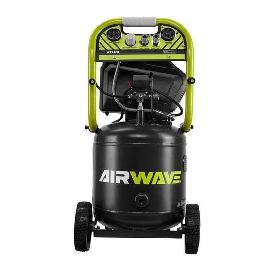
- Page 1 40L 1.8HP OiL Free Direct Drive UPrigHt Air cOmPressOr OPerAtOr's mANUAL OrigiNAL iNstrUctiONs Important! It is essential you read the instructions in this manual before starting and operating this machine. Subject to technical modifications.
- Page 2 DescriPtiON 1. Handle 19. Quick connect air fitting 2. Regulated pressure gauge 20. Quick coupler 3. Quick connect coupler 21. On 4. Pressure relief valve 22. Off 5. Check valve 23. To open 6. Tank pressure gauge 24. Drain valve lever 7.
- Page 3 Fig. 2 Fig. 3 Fig. 3 Fig. 4 Fig. 6 Fig. 5...
- Page 4 Fig. 7 Fig. 8 Fig. 9 Fig. 10 Fig. 11 Fig. 12 Fig. 13 Fig. 14...
-
Page 5: General Safety Warnings
operation is dusty. geNerAL sAFety wArNiNgs ■ Protect your hearing. Wear hearing protection during extended periods of operation. wArNiNg ■ Do not overreach. Keep proper footing and balance Read and understand all instructions. Failure to follow at all times. all instructions listed below, may result in electric shock, ■... - Page 6 not be used for a while, it is best to leave drain valve A respirator may be necessary in dusty environments open until such time as it is to be used. This will allow or when spraying paint. Do not carry while painting. moisture to completely drain out and help prevent ■...
-
Page 7: Product Specifications
wArNiNg PrODUct sPeciFicAtiONs Do not use this product if any parts on the packing Rated motor power 1350 W list are already assembled to your product when you unpack it. Parts on this list are not assembled to the Rated current product by the manufacturer and require customer Air outlets 2 pcs, 6.35mm (1/4”) -
Page 8: Operation
3. Insert a washer at the other end. This will help you to avoid damaging the wheel or the air 4. Secure the rubber foot with a hex nut. compressor by rolling it over items in its path. 5. Repeat the above steps to install the other foot on the Ensure the air compressor is unplugged, make sure the right. -
Page 9: Using The Air Compressor
DrAiNiNg tHe tANk wArNiNg See figure 12-13. Never exceed the air tool’s pressure rating as To prevent tank corrosion and keep moisture out of the recommended by the manufacturer. When using air used, the air tank of the compressor should be drained this air compressor as an inflation device, always daily. -
Page 10: Reset Button
wArNiNg mAiNteNANce If air leaks after the ring has been released, or if the valve is stuck and cannot be actuated by the ring, wArNiNg do not use the air compressor until the safety valve When servicing use only original replacement parts. has been replaced. -
Page 11: Environmental Protection
eNvirONmeNtAL PrOtectiON risk of fire or explosion. Spray area must be well ventilated. Do not smoke Recycle raw materials instead of disposing while spraying or spray where spark or of as waste. The machine, accessories flame is present. Keep compressors as and packaging should be sorted for far from the spraying area as possible. -
Page 12: Troubleshooting
trOUBLesHOOtiNg PrOBLem cAUse POssiBLe sOLUtiON Compressor will not run Loss of power or overheating Check for proper use of extension cord No electrical power Check to be sure unit is plugged in Check fuse/breaker Blown shop/house fuse Replace shop/house blown fuse Shop/house breaker open Reset shop/house breaker, determining why problem happened... - Page 13 PrOBLem cAUse POssiBLe sOLUtiON Compressor runs continuously Defective pressure switch Take compressor to service centre Excessive air usage Take compressor to service centre Decrease air usage; compressor not large enough for tool’s requirement Piston rings are worn Replace piston rings; inlet filter is blocked, call customer service for...
-
Page 14: Parts List
PArts List... - Page 15 Description Description Description Description Crankcase - ZL108 Thermal cutout Bolt M6 x 40 Air filter Bolt M6 x 35 Nut 5 Exhaust pipe Φ28 Handle Spring washer 6 30UF Capacitor Tank Bolt M8 x 10 Crank shaft - QT500-7 Bearing 6204-2RZ Nut M8 Handle sleeve Bolt M6 x 18...
- Page 16 Techtronic Industries (Australia) Pty. Ltd. Level 1, 660 Doncaster Road Doncaster, VIC 3108, Australia Techtronic Industries New Zealand Ltd. 18-26 Amelia Earhart Avenue Mangere, Auckland 2022, New Zealand...