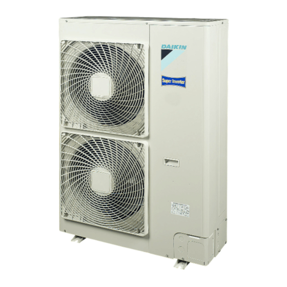
Summary of Contents for Daikin RZQ-BW1
- Page 1 INSTALLATION MANUAL Split System air conditioners RZQ71C7V1B RZQ100C7V1B RZQ125C7V1B RZQ140C7V1B RZQ100B8W1B RZQ125B8W1B RZQ140B8W1B...
- Page 2 B 2 B 2 D 2 D 2 D 2 D 2 L 1 L 1 B 1 B 1 L 2 L 2 D 1 D 1 B 2 B 2 D 2 D 2 D 2 D 2 L 1 L 1 B 1 B 1 L 2 L 2...
- Page 3 3PW34877-4B...
-
Page 4: Table Of Contents
ELECTRIC SHOCK, SHORT-CIRCUIT, LEAKS, FIRE OR to fall of equipment. OTHER DAMAGE TO THE EQUIPMENT. BE SURE ONLY TO USE ACCESSORIES MADE BY DAIKIN WHICH ARE Make certain that all electrical work is carried out by SPECIFICALLY DESIGNED FOR USE WITH THE qualified personnel according to the local laws and... -
Page 5: Before Installation
WARNING CAUTION Live parts can be easily touched by accident. Do not install the air conditioner in places such as the Never leave the unit unattended during installation or following: servicing when the service panel is removed. Where there is mist of mineral oil, oil spray or When planning to relocate former installed units, you vapour for example a kitchen. -
Page 6: Selecting Installation Site
Accessories For RZQ100~140B8W1B only Check if the following accessories are included with the unit This is a class A product. In a domestic environment this product may cause radio interference in which case the user may be required to take adequate Installation manual measures. -
Page 7: Precautions On Installation
If you install the unit on a building frame, please install a NSTALLATION SERVICING SPACE waterproof plate (within 150 mm of the underside of the unit) or use a drain plug kit (option) in order to avoid the drainwater The numerical figures used in here represent the dimensions for the dripping. -
Page 8: Refrigerant Pipe Size And Allowable Pipe Length
Refrigerant pipe size In case of installing multiple units (2 units or more) in lateral connection per row. Refer to figure 3 for twin system, to figure 4 for triple system and to figure 5 for double twin system. Main pipe (pipe between outdoor and first branch). The pipes should have the same size as the outdoor connections. -
Page 9: Precautions On Refrigerant Piping
Allowable pipe length and height difference Existing or pre-installed piping can be used See the table below concerning lengths and heights. Refer to figures Piping must comply with the criteria below. 2, 3, and 5. Assume that the longest line in the figure corresponds •... -
Page 10: Refrigerant Piping
In case of simultaneous operating system EFRIGERANT PIPING Upward and downward piping should be performed at the main piping line. Field pipes can be installed in four directions. Use branch piping kit (optional) for branching refrigerant pipes. Precautions to be taken. (For details, refer to the manual attached to branch piping kit.) Install the branch pipes horizontally (with a maximum inclination of 15°) or vertically. - Page 11 Cautions for handling service port Since the side boards may be deformed if only a torque wrench is used when loosening or tightening flare nuts, always lock the Always use a flexible charge hose with a push-rod and valve to stop valve with a wrench and then use a torque wrench.
-
Page 12: Evacuating
If a torque wrench is not available, be aware that the tightening VACUATING torque may increase suddenly. Do not tighten nuts any further than to the angle as listed. Do not purge the air with refrigerants. Use a vacuum pump to vacuum the installation. -
Page 13: Charging Refrigerant
HARGING REFRIGERANT For pair system Table 1: Additional charging of refrigerant <unit: kg> Important information regarding the refrigerant used Standard liquid pipe size This product contains fluorinated greenhouse gases covered by the Connected piping length is between Kyoto Protocol. Do not vent gases into the atmosphere. Model 30~40 m 40~50 m... - Page 14 Precaution for pumping-down operation In case of complete recharge of the refrigerant, please first The outdoor unit is equipped with a low pressure switch or a low execute vacuuming. Execute this vacuuming from the pressure sensor to protect the compressor. service port.
-
Page 15: Electrical Wiring Work
Lay the electrical wiring so that the front cover does not rise up LECTRICAL WIRING WORK when doing wiring work and attach the front cover securely. All wiring must be performed by an authorized electrician. All components procured on the site and all electric construction should comply with the applicable local and national codes. -
Page 16: Test Operation
Precautions on wiring of power supply and inter-unit Specifications of standard wiring components wiring RZQ71V1 RZQ100~140V1 RZQ100~140W1 Use a round crimp-style terminal for connection to the power Minimum circuit supply terminal board. In case it cannot be used due to 17.7 28.2 17.7... -
Page 17: Disposal Requirements
Test run Failure diagnosis at the moment of first installation Be sure to turn power on at least 6 hours before starting In case nothing is displayed on the remote controller (the current set operation in order to protect the compressor. temperature does not display), check for any of the following abnormalities before you can diagnose possible malfunction codes. -
Page 18: Wiring Diagram
IRING DIAGRAM : Wire clamp : Black : Terminal : Green : Connector : Brown : Relay connector : Blue : Field wiring : Orange : Red : White : Yellow : Refer to the service manual for connecting wiring to X6A. : The position of the selector switches (DS1) indicate the factory setting. - Page 19 NOTES NOTES...
- Page 20 4PW40417-1...


