Table of Contents
Advertisement
Quick Links
Installation Instructions
for use by heating contractor
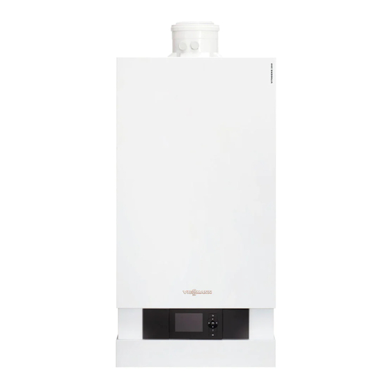
Vitodens 200-W, B2HB
Models 19, 26, 35, 68, 94, 125
Wall-mounted, gas-fired condensing boiler
For operation with natural gas and liquid propane gas
Heating input: 12 to 125 MBH
3.5 to 37 kW
VITODENS
5461 884 - 14
01/2019
200-W
r
H
Product may not be exactly as shown
IMPORTANT
Read and save these instructions
for future reference.
Please file in Service Binder
Advertisement
Table of Contents

Related Manuals for Viessmann B2HB009


Summary of Contents for Viessmann B2HB009
- Page 1 Installation Instructions for use by heating contractor Vitodens 200-W, B2HB Models 19, 26, 35, 68, 94, 125 Wall-mounted, gas-fired condensing boiler For operation with natural gas and liquid propane gas Heating input: 12 to 125 MBH 3.5 to 37 kW VITODENS 200-W Product may not be exactly as shown...
-
Page 2: Safety
Follow the manufacturing facilities. Viessmann maintenance schedule of the boiler contained Contaminated combustion air will damage the boiler in this manual. and may lead to substantial property damage, severe Operating and Service Documentation personal injury and/or loss of life. -
Page 3: About These Installation Instructions
Safety Vitodens 200-W B2HB 19 to 35, 68 to 125 Installation Safety, Installation and Warranty Requirements (continued) Suppliers of fiberglass wool products recommend the Fiberglass wool and ceramic fiber materials following precautions be taken when handling these materials: WARNING - Avoid breathing fiberglass dust and contact with skin and eyes. -
Page 4: Table Of Contents
Table of Contents Vitodens 200-W B2HB 19 to 35, 68 to 125 Installation Page Safety Safety, Installation and Warranty Requirements....2 Product documentation..........2 Warranty..............2 Licensed professional heating contractor....2 Contaminated air............2 Advice to owner............2 Operating and Service Documentation......2 Carbon monoxide.............2 Fresh air..............2 Equipment venting...........2 About these Installation Instructions......3 General Information... - Page 5 Table of Contents Vitodens 200-W B2HB 19 to 35, 68 to 125 Installation Page Boiler Connections (continued) Safety Connections...........29 Installing boiler safety devices.........29 Low water cut-off..........29 Waterside Flow............30 Waterside flow (primary circuit).......30 Heating Circuit / Boiler Pumps........31 Low-Loss Header Application........31 Installation Examples..........32 General..............32 Clearances............32...
-
Page 6: General Information
Proper completion of the Maintenance Record - Service Instructions by the heating contractor is also required. - Operating Instructions and User’s Information Manual - Instructions of other Viessmann products utilized and Working on the equipment installed The installation, adjustment, service, and maintenance... -
Page 7: Csd-1 Field Testing Of High Limit Switches
CSD-1 Field Testing of High Limit Switches for Vitodens boilers – where required by law. VIESSMANN IS NOT RESPONSIBLE FOR ANY DAMAGES THAT THE FOLLOWING TEST PROCEDURE MAY RESULT IN BY OVERHEATING THE SYSTEM. -
Page 8: Applicability
General Information Vitodens 200-W B2HB 19 to 35, 68 to 125 Installation Applicability CAUTION The boiler serial number must be provided when ordering replacement parts. Some replacement parts are not reverse compatible with previous versions of the Vitodens 200-W B2HB boiler. IMPORTANT When ordering replacement parts, provide either the 16-digit boiler serial number (on the bar code label) or... -
Page 9: Mechanical Room
General Information Vitodens 200-W B2HB 19 to 35, 68 to 125 Installation Mechanical Room During the early stages of designing a new home, we recommend that proper consideration be given to constructing a separate mechanical room dedicated to the gas- or oil-fired heating equipment and domestic hot water storage tank(s). The boiler must be located in a heated indoor area, near a floor drain, and as close as possible to a wall. -
Page 10: Before Set-Up
(spraying, splashing, etc.) during boiler operation and service. Minimum Clearances Recommended minimum service clearances For typical Vitodens installations, Viessmann recommends installing the boiler with the clearances shown in the illustration on the left. Note: The 12 in. (305 mm) side clearance specified is... -
Page 11: Preparing The Connections
Boiler Connections Vitodens 200-W B2HB 19 to 35, 68 to 125 Installation Preparing the Connections Use an approved pipe sealant or teflon tape when connecting the following installation fittings. This section constitutes an overview only! Refer to subsequent sections for detailed information on individual piping connections. - Page 12 Boiler Connections Vitodens 200-W B2HB 19 to 35, 68 to 125 Installation Preparing the Connections (continued) This section constitutes an overview only! Refer to Note: When preparing gas, water and electrical subsequent sections for detailed information on individual connections in the field, see section entitled piping connections.
-
Page 13: Wall Mounting
Boiler Connections Vitodens 200-W B2HB 19 to 35, 68 to 125 Installation Wall Mounting Fitting the wall mounting bracket Installing the wall mounting bracket Following are the installation instructions for the mounting The Vitodens 200-W B2HB can be wall-mounted on a bracket on each material. -
Page 14: Boiler Mounting Bracket
Boiler Connections Vitodens 200-W B2HB 19 to 35, 68 to 125 Installation Wall Mounting (continued) Boiler mounting bracket Install the boiler mounting bracket to the wall studs. Ensure the mounting bracket is level. To mount on wood or metal studs a cross bar or frame may be required as reinforcement. -
Page 15: Mounting The Boiler
Boiler Connections Vitodens 200-W B2HB 19 to 35, 68 to 125 Installation Wall Mounting (continued) Mounting the boiler 1. Remove the external accessories connection box cover. 2. Loosen the screws at the bottom of the boiler (do not remove completely). 3. -
Page 16: Frame Mounting
Boiler Connections Vitodens 200-W B2HB 19 to 35, 68 to 125 Installation Frame Mounting The boiler stand is used for free-standing installation of a single boiler within the mechanical room. When using the boiler stand, ensure that the stand is securely fastened to the floor (recommended concrete expansion anchors are Hilti model KB-TZ e x 4 or equivalent. -
Page 17: Mounting The Boiler
Boiler Connections Vitodens 200-W B2HB 19 to 35, 68 to 125 Installation Frame Mounting (continued) Mounting the boiler 1. Remove the external accessories connection box cover. 2. Loosen the screws at the bottom of the boiler (do not remove completely). 3. -
Page 18: Connections
Boiler Connections Vitodens 200-W B2HB 19 to 35, 68 to 125 Installation Connections Connecting power The Vitodens 200-W boiler has an external accessories connection box installed, which requires a 120VAC/12A power supply. Refer to the wiring diagram (see page 45). Boiler venting The Vitodens 200-W B2HB boiler comes with a pre-installed vent pipe adaptor. -
Page 19: Gas Connection And Piping
Boiler Connections Vitodens 200-W B2HB 19 to 35, 68 to 125 Installation Connections (continued) Gas connection and piping 1. Refer to current CAN/CSA B149.1 and .2 or National Fuel Gas Code ANSI Z223.1/NFPA 54, as well as local codes for gas piping requirements and sizing. Pipe size to the boiler must be determined based on: - pipe length - number of fittings... -
Page 20: Gas Piping Pressure Test
Boiler Connections Vitodens 200-W B2HB 19 to 35, 68 to 125 Installation Connections (continued) Gas piping pressure test Heating water connections When performing the gas piping pressure test, ensure the 1. Thoroughly flush heating system (particularly before following requirements are met. connecting the boiler to an existing system). -
Page 21: Dhw Storage Tank Information
Viessmann DHW storage tank when mounting and securing DHW tank temperature sensor %. WARNING If a DHW storage tank other than a Viessmann Vitocell 100 or 300 tank is used, the installer must verify proper operation of the Viessmann DHW tank temperature sensor with original manufacturer of the tank. -
Page 22: Accessing The Control Unit Connections
Boiler Connections Vitodens 200-W B2HB 19 to 35, 68 to 125 Installation Connections (continued) Accessing the control unit connections 1. Remove both screws from the junction box cover and set screws aside. 2. Loosen both retaining screws as shown (do not remove). - Page 23 Boiler Connections Vitodens 200-W B2HB 19 to 35, 68 to 125 Installation Connections (continued) 5. Tilt the bottom of the external accessory connection box cover forward. 6. Pull the cover up to clear the locating pins and out to remove, then set aside. 7.
-
Page 24: Routing The Connecting Cables
Boiler Connections Vitodens 200-W B2HB 19 to 35, 68 to 125 Installation Connections (continued) 12. Route all connecting cables to the appropriate areas and secure the cables to the control base using existing strain reliefs as shown. CAUTION When running and securing connecting cables on site, ensure that the maximum permissible temperatures of the cables are not exceeded. -
Page 25: Connecting Dhw Sensor
Boiler Connections Vitodens 200-W B2HB 19 to 35, 68 to 125 Installation Connections (continued) Connecting DHW sensor 1. Attach the DHW sensor using the quick connect plugs from the boiler control board (see page 24). Install DHW tank temperature sensor as described in the Vitocell Installation Instructions supplied with the DHW storage tank. -
Page 26: Boiler Control Base
Boiler Connections Vitodens 200-W B2HB 19 to 35, 68 to 125 Installation Connections (continued) Boiler control base OUTDOOR Note: See wiring diagram on page 45 for connection to TEMPERATURE TEMPERATURE the external accessory connection box. SENSOR SENSOR... -
Page 27: External Accessory Connection Box
Boiler Connections Vitodens 200-W B2HB 19 to 35, 68 to 125 Installation Connections (continued) External accessory connection box IMPORTANT Note: See wiring diagram on page 45 for connection to the control base. Electrical installations must comply with the latest edition of: In the U.S.A., the National Electrical Code (NEC), ANSI/NFPA 70 and any other state, local codes and/or regulations. -
Page 28: Condensate Connection
Boiler Connections Vitodens 200-W B2HB 19 to 35, 68 to 125 Installation Connections (continued) Condensate connection The Vitodens 200-W B2HB boiler comes with a built- in condensate trap. An external trap is not required when connecting the field drain to flexible discharge tubing. -
Page 29: Safety Connections
Boiler Connections Vitodens 200-W B2HB 19 to 35, 68 to 125 Installation Safety Connections Installing boiler safety devices 1. Remove the pressure relief valve, drain valve and fittings from the box. 2. Apply sufficient amount of pipe sealant to both ends of all pipe fittings B,D,F and H and install onto tees A, and E. -
Page 30: Waterside Flow
6.4 (1453) (as stated above), falls below the minimum flow rate 25ºF (14ºC) rise GPM (L/h) 5.1 (1163) or if system flow rate is unknown, Viessmann strongly 30ºF (17ºC) rise GPM (L/h) 4.3 (969) recommends the installation of a low-loss header. -
Page 31: Heating Circuit / Boiler Pumps
Boiler Connections Vitodens 200-W B2HB 19 to 35, 68 to 125 Installation Heating Circuit / Boiler Pumps Viessmann offers a variety of Grundfos heating circuit/ Before using the following pumps for a DHW tank boiler pumps which meet typical Vitodens system application, find out the proper pressure drop through the installation requirements (see “Heating circuit pump... -
Page 32: Installation Examples
Specific system layouts may be further discussed with the local If a DHW storage tank other than a Viessmann Vitocell Viessmann sales representative office. 100 or 300 tank is used, the installer must verify proper operation of the Viessmann DHW tank temperature sensor with the original manufacturer of the tank. -
Page 33: System Layout 1-9
Boiler Connections Vitodens 200-W B2HB 19 to 35, 68 to 125 Installation System Layout 1 Vitodens 200-W, B2HB with a direct-connected heating circuit Legend Installation of ... A Vitodens 200-W B2HB boiler with radiator heating circuit (high-temp. circuit) ■ Vitotronic 200, HO1B outdoor reset control DHW production ■... - Page 34 28/20 The low-loss header is available as accessory part. Low-loss header Pressure relief valve IMPORTANT Viessmann temperature sensor for low-loss header ? Please note location of expansion tank. Heating circuit pump 28/20 DHW circulating pump F must pump into the Vitodens Function based on coding of address 53 200-W B2HB boiler (as illustrated).
- Page 35 200-W B2HB boiler (as illustrated). An undersized pump may cause short-cycling and/or improper operation of the boiler. Viessmann STRONGLY recommends using a low-loss header and a boiler pump in this system layout.
- Page 36 Boiler Connections Vitodens 200-W B2HB 19 to 35, 68 to 125 Installation System Layout 4 Vitodens 200-W, B2HB with... - DHW storage tank - one direct-connected heating circuit - one heating circuit with a mixing valve Installation of different heating circuits... Legend Vitodens 200-W B2HB boiler with radiator heating circuit (high-temp.
- Page 37 DHW circulating pump sA Heating circuit pump IMPORTANT Low-loss header Viessmann temperature sensor for low-loss header ? Heating circuit pump DHW circulating pump O must pump into the Vitodens 28/20 200-W B2HB boiler (as illustrated). Function based on coding of address 53...
- Page 38 Temperature and pressure relief valve temperature level of the under floor heating circuit, is Low-loss header controlled by an accessory kit for a heating circuit with Viessmann temperature sensor for low-loss header ? a mixing valve. Pressure relief valve DHW recirculation pump...
- Page 39 Boiler Connections Vitodens 200-W B2HB 19 to 35, 68 to 125 Installation System Layout 7 Vitodens 200-W, B2HB with... - direct-connected heating circuit - one heating circuit with system separation Installation of different heating circuits... Legend radiator heating circuit (high-temp. circuit) ■...
- Page 40 Boiler Connections Vitodens 200-W B2HB 19 to 35, 68 to 125 Installation System Layout 8 Vitodens 200-W, B2HA/B2HB with... - DHW storage tank - low-loss header - three zone circuits Legend Installation of different heating circuits... Vitodens 200-W boilers DHW production ■...
- Page 41 - low-loss header - multiple heating circuits with mixing valves - one heating circuit without mixing valve When designing a system as illustrated above, please contact your local Viessmann Sales Representative for assistance. Legend Vitodens 200-W B2HB boiler with Vitotronic *1 Contact your local Sales Representative for details.
-
Page 42: Alternative Dhw Connection
Boiler Connections Vitodens 200-W B2HB 19 to 35, 68 to 125 Installation Alternative DHW Connection The following piping diagram reflects an alternative connection for the DHW tank only and applies to system layouts 2, 5, 6 and 8. The boiler control pump logic function must be programmed in the Service Instructions. *Note: When using a low loss header in the system, the DHW connections can be made downstream of the low loss header. -
Page 43: Boiler In Heating/Cooling Application
Close valve “v1” and open valve “v2”. Heating season starts: Close valve “v2” and open valve “v1”. IMPORTANT Viessmann strongly suggests that the valves illustrated be labelled “v1” and “v2”. IMPORTANT In the illustration, the circulating pump must be operated from a separate on/off switch, not from the pump aquastat on the boiler control. -
Page 44: Boiler With Low Water Cut-Off
Boiler Connections Vitodens 200-W B2HB 19 to 35, 68 to 125 Installation Boiler with Low Water Cut-off Boiler with low water cut-off (remote-mounted, field supplied) Automatic Automatic air vent air vent A low water cut-off may be required by local codes. Do not install an isolation valve between boiler and low water cut-off. -
Page 45: Control Connections
Control Connections Vitodens 200-W B2HB 19 to 35, 68 to 125 Installation Overview of Electrical Connections, Models B2HB 19 to 35, 68 to 125 CAUTION WARNING DISCONNECT POWER BEFORE Label all wires prior to disconnection SERVICING BOILER. when servicing controls. Wiring errors can cause improper and dangerous operation. - Page 46 Control Connections Vitodens 200-W B2HB 19 to 35, 68 to 125 Installation Overview of Electrical Connections, Models B2HB 19 to 35, 68 to 125 (continued) Legend IMPORTANT Outdoor Temperature Sensor Supply Temperature Sensor/Low Loss Header Electrical installations must comply with the latest edition of: Boiler Temperature Sensor DHW Temperature Sensor In the U.S.A., the National Electrical Code (NEC),...
-
Page 47: Electrical Connections
Control Connections Vitodens 200-W B2HB 19 to 35, 68 to 125 Installation Electrical Connections Power supply connection of accessories Cabling required for: The power supply connection of accessories can be made H outdoor temperature sensor directly at the control. The connection is activated and H Vitotronic 200-H, HK1B mixing valve control deactivated with the system on/off switch. -
Page 48: Accessing The X3 Plug
Control Connections Vitodens 200-W B2HB 19 to 35, 68 to 125 Installation Accessing the X3 Plug 1. Remove the control unit cover (see page 23). 2. Remove the X3 plug from the control board. Install the required sensors as per instructions. Reinstall the control cover. -
Page 49: Connecting The Outdoor Temperature Sensor
Control Connections Vitodens 200-W B2HB 19 to 35, 68 to 125 Installation Connecting the Outdoor Temperature Sensor 1. Remove cover of outdoor temperature sensor. 2. Mount wall-mount base (cable entry must point downward). IMPORTANT The outdoor temperature sensor should be mounted 6.6 to 8.2 ft. -
Page 50: External 0-10 Volt Signal Connection
Control Connections Vitodens 200-W B2HB 19 to 35, 68 to 125 Installation External 0-10 Volt Signal Connection 1. Connect the external 0-10V signal to plug 0-10V located in the extension module EA1. 2. Ensure correct polarity. 3. See chart for maximum possible boiler water Extension Module EA1 temperature and required signal. -
Page 51: Connecting A 24Vac Thermostat
Control Connections Vitodens 200-W B2HB 19 to 35, 68 to 125 Installation Connecting a 24VAC Thermostat 1. Connect normally open dry contact of the switching relay (‘T-T’ contact) to terminal DE1, DE2 or DE3 of the EA1 module located in the boiler electrical junction box. -
Page 52: Thermostat Connection
Control Connections Vitodens 200-W B2HB 19 to 35, 68 to 125 Installation Thermostat Connection Legend Refer to the boiler Installation Instructions for A Room thermostat (dry contact) zone circuit 1 locating and accessing the integrated EA1 module. B Room thermostat (dry contact) zone circuit 2 C Room thermostat (dry contact) zone circuit 3 D EA1 module (integrated into the boiler) -
Page 53: Pump Connection
Control Connections Vitodens 200-W B2HB 19 to 35, 68 to 125 Installation Pump Connection Connection to boiler Pump output assignment is done using the start-up wizard. A maximum of 2 zone circuit pumps can be connected to the boiler additional pumps will require the use of an AM1 extension module. -
Page 54: Lon Module
Control Connections Vitodens 200-W B2HB 19 to 35, 68 to 125 Installation LON Module Installing the LON module to the boiler control board 1. Remove the control cover (see page 23). 2. Insert the LON module into the boiler control board. 3. -
Page 55: Accessory Kit
Control Connections Vitodens 200-W B2HB 19 to 35, 68 to 125 Installation Accessory Kit Accessory kit connections for heating circuit with Boiler mixing valve Control The mixing valve controller kit can only be used with wall-mounted gas-fired hot water heating boilers and a weather-responsive control;... -
Page 56: Closing The External Accessory Connection Box
Control Connections Vitodens 200-W B2HB 19 to 35, 68 to 125 Installation Closing the External Accessory Connection Box Closing the External Accessory Connection Box 4. Tilt the top of the external accessory connection box cover forward. 5. Drop down over the locating pins and set the cover in place. -
Page 57: Reinstalling The Front Enclosure Panel
IMPORTANT Read and follow, where applicable, the safety instructions of all labels and stickers attached to boiler surfaces. Do not remove any of these instructions. Contact Viessmann if any replacement labels are required. -
Page 58: Additional Information
Additional Information Vitodens 200-W B2HB 19 to 35, 68 to 125 Installation Technical Data Boiler Model No. 200-W B2HB 19, 68 26, 94 35, 125 CSA input Natural Gas (NG) 12-68 19-94 19-125 (kW) (3.5-20) (5.5-27) (5.5-37) 12-68 31-94 31-125 CSA input Liquid Propane Gas (LPG) (kW) (3.5-20) - Page 59 Side wall co-axial vent installation must include Viessmann protective screen! For details refer to the Installation Instructions for the Vitodens 200-W, B2HB Venting System. For information regarding other Viessmann System Technology componentry, please reference documentation of respective product. Note: For high altitude installation at 10,000 ft. (3000 m) the input for model B2HB 19, 26 35, 68, 94, 125 will have...
-
Page 60: Installation Fittings
Additional Information Vitodens 200-W B2HB 19 to 35, 68 to 125 Installation Installation Fittings Parts 0301 Nipple ¾ in. x 2 in. 0302 Sediment faucet ¾ in. 0303 Tee, ¾ in. 0304 Nipple ¾ in. x 4b in. 0306 Gas ball valve ¾ in. 0312 Pressure relief valve, 30 psig Other Parts (not illustrated) 0309 Accessory pack (metal stud mount kit) -
Page 61: Lighting And Operating Instructions
Additional Information Vitodens 200-W B2HB 19 to 35, 68 to 125 Installation Lighting and Operating Instructions FOR YOUR SAFETY READ BEFORE OPERATING W A R N I N G: If you do not follow these instructions exactly, a fire or explosion may result causing property damage, personal injury or loss of life. - Page 62 Vitodens 200-W B2HB 19 to 35, 68 to 125 Installation...
- Page 63 Vitodens 200-W B2HB 19 to 35, 68 to 125 Installation...
- Page 64 Vitodens 200-W B2HB 19 to 35, 68 to 125 Installation...