Advertisement
Quick Links
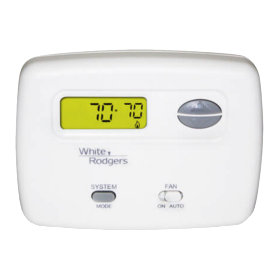
Installation Instructions for
Heating & Air Conditioning
Non- Programmable, Auto Changeover
Multi-stage/Heat Pump Thermostat
YOUR THERMOSTAT REPLACES
Description
Heat Pump (No Aux or Emergency Heat)
Heat Pump (with Aux or Emergency Heat)
Standard Heat & Cooling Systems
Two Stage Heat & Two Stage Cool
Standard Heat Only Systems
Millivolt Heat Only Systems - Floor or Wall Furnaces
Standard Central Air Conditioning
Gas or Oil Heat
Electric Furnace
Hydronic (Hot Water) Zone Heat - 2 Wires
Hydronic (Hot Water) Zone Heat - 3 Wires
* Requires common for 24 VAC at the thermostat
2
THERMOSTAT DETAILS
Mounting
Hole
Figure 1. Thermostat Base
WHITE-RODGERS
EMERSON ELECTRIC CO.
9797 REAVIS ROAD
ST. LOUIS, MISSOURI 63123-5398
www.white-rodgers.com
IF73
1F73
Yes*
Yes*
Yes*
Yes*
Yes*
No
Yes*
Yes*
Yes*
Yes*
No
O/B Terminal
Switches Selection
Mounting
Hole
O
B
(O/B)Y2 E/W1
R
C
L
Y1
W2
G
ELEC
GAS
Elec - Gas
Switch
CONTENTS
Preparations .................................................. 1
Thermostat Details ........................................ 1
Removing Old Thermostat ......................... 1-2
Mounting and Wiring .................................. 2-4
Check Thermostat Operation ..................... 5-6
Specifications ................................................ 6
Operation ...................................................... 6
Troubleshooting ......................................... 7-8
1
PREPARATIONS
Assemble tools required as shown below.
HAND OR POWER
DRILL WITH 3/16 INCH
DRILL BIT, IF NEEDED
Failure to follow and read all instructions carefully
before installing or operating this control could cause
personal injury and/or property damage.
3
REMOVING OLD THERMOSTAT
To prevent electrical shock and/or equipment damage,
disconnect electrical power to the system at the main
fuse or circuit breaker until installation is complete.
Before removing wires from old thermostat's switching subbase,
label each wire with the terminal designation it was removed from.
1. Remove Old Thermostat: A standard heat/cool thermostat
consists of three basic parts:
a. The cover, which may be either a snap-on or hinge type.
b. The base, which is removed by loosening all captive screws.
c. The switching subbase, which is removed by unscrewing
the mounting screws that hold it on the wall or adaptor plate.
2. Shut off electricity at the main fuse box until installation is
complete. Ensure that electrical power is disconnected.
3. Remove the front cover of the old thermostat. With wires still
attached, remove wall plate from the wall. If the old thermostat
has a wall mounting plate, remove the thermostat and the wall
mounting plate as an assembly.
4. Identify each wire attached to the old thermostat.
5. Disconnect the wires from the old thermostat one at a time. DO
NOT LET WIRES FALL BACK INTO THE WALL.
6. Install new thermostat using the following procedures.
Printed in U.S.A.
FLAT BLADE SCREWDRIVER
WIRE CUTTER/STRIPPER
SPIRIT LEVEL OR PLUMB BOB AND LINE OPTIONAL-
THERMOSTAT DOES NOT NEED TO BE LEVEL TO WORK PROPERLY
CAUTION
!
PART NO. 37-6429A
0230
Advertisement

Related Manuals for White Rodgers IF73


Summary of Contents for White Rodgers IF73
-
Page 1: Table Of Contents
Thermostat Details ........1 Removing Old Thermostat ......1-2 Heating & Air Conditioning Mounting and Wiring ........2-4 Check Thermostat Operation ..... 5-6 IF73 Specifications ..........6 Operation ............6 Non- Programmable, Auto Changeover Troubleshooting ......... 7-8 Multi-stage/Heat Pump Thermostat... -
Page 2: Removing Old Thermostat
REMOVING OLD THERMOSTAT CAUTION CONTINUED FROM PAGE 1 Take care when securing and routing wires so they do ATTENTION! This product does not contain mercury. How- not short to adjacent terminals or rear of thermostat. ever, this product may replace a unit which contains mercury. Personal injury and/or property damage may occur. - Page 3 MOUNTING AND WIRING CONTINUED FROM PAGE 2 E/W1 O/B/Y2 THERMOSTAT SYSTEM See Note ** SYSTEM Changeover MONITOR Emergency Relay* SWITCH Compressor Relay Relay Relay Contactor (Stage 2) 24 VAC 120 VAC Neutral * Changeover Relay is energized in COOL when O/B switch is in the “O” position TRANSFORMER Changeover Relay is energized in HEAT when O/B switch is in the “B”...
- Page 4 MOUNTING AND WIRING CONTINUED FROM PAGE 3 O/B/Y2* E/W1 THERMOSTAT SYSTEM Heat Compressor Relay Contactor Stage 1 Stage 2 24 VAC 120 VAC Compressor Heat Neutral Contactor Relay Relay TRANSFORMER Stage 1 Stage 2 (Class II, Current Limited) *O/B Switch must be in “O” position Figure 5.
-
Page 5: Check Thermostat Operation
Cooling System CHECK THERMOSTAT OPERATION 1. Press SYSTEM key to select the Snowflake icon ( ). NOTE 2. Press to adjust thermostat setting below room tempera- ture. The blower should come on immediately on high speed, To prevent static discharge problems, touch side of ther- followed by cold air circulation. -
Page 6: Specifications
CHECK THERMOSTAT OPERATION Configuration Menu CONTINUED FROM PAGE 4 Step Press Button(s) Displayed Press (Factory Default) to select: 9 Displays currently programmed set temperature (this is blank Set SYSTEM switch to OFF when SYSTEM switch is in the OFF position). no HP 10 Stage 1 &... -
Page 7: Troubleshooting
OPERATION CONTINUED FROM PAGE 5 Automatic System Changeover system cycle was heat, the HEAT setpoint will be displayed. If the When the thermostat is in the AUTO mode, both the Flame and Snowflake icons are displayed. The thermostat will call for heat room temperature raises above the HEAT setpoint and the COOL or cool depending on the room temperature. - Page 8 TROUBLESHOOTING CONTINUED FROM PAGE 7 Symptom Possible Cause Corrective Action Furnace Cycles Too Fast or Too Slow 1. The location of the thermostat and/or the Digital thermostats normally provide precise (narrow or wide temperature swing) size of the Heating System may be temperature control and may cycle faster than influencing the cycle rate.