Majestic MARQ36IN-B Installation Manual
Hide thumbs
Also See for MARQ36IN-B:
- Owner's manual (29 pages) ,
- Glass refractory installation instructions (5 pages) ,
- Owner's manual (33 pages)
Table of Contents
Advertisement
Quick Links
CAUTION! Risk of Fire! DO NOT store instruction manuals inside fireplace cavity.
High temperatures could cause a fire.
INSTALLER: Leave this manual with the appliance, not inside the appliance.
CONSUMER: Retain this manual for future reference. Do not store inside the appliance.
NOTICE: DO NOT discard this manual!
MARQUIS
SERIES
Models:
MARQ36IN-B, MARQ42IN-B
This appliance may be installed as an OEM
installation in manufactured home (USA
only) or mobile home and must be installed
in accordance with the manufacturer's
instructions and the Manufactured Home
Construction and Safety Standard, Title 24
CFR, Part 3280 in the United States, or the
Standard for Installation in Mobile Homes,
CAN/CSA Z240 MH Series, in Canada.
This appliance is only for use with the type(s)
of gas indicated on the rating plate. This
appliance is not convertible for use with other
gases, unless a certified kit is used.
Installation Manual
Installation and Appliance Setup
Majestic MARQ36IN-B, MARQ42IN-B Installation Manual • 2614-980 Rev. D • 4/19
WARNING:
FIRE OR EXPLOSION HAZARD
Failure to follow safety warnings exactly
could result in serious injury, death, or
property damage.
• DO NOT store or use gasoline or other flam-
mable vapors and liquids in the vicinity of this
or any other appliance.
• What to do if you smell gas
- DO NOT try to light any appliance.
- DO NOT touch any electrical switch. DO
NOT use any phone in your building.
- Leave the building immediately.
- Immediately call your gas supplier from
a neighbor's phone. Follow the gas sup-
plier's instructions.
- If you cannot reach your gas supplier, call
the fire department.
• Installation and service must be performed
by a qualified installer, service agency, or the
gas supplier.
DANGER
DO NOT TOUCH GLASS
NEVER ALLOW CHILDREN
A barrier designed to reduce the risk of
burns from the hot viewing glass is provided
with this appliance and shall be installed for
the protection of children and other at-risk
individuals.
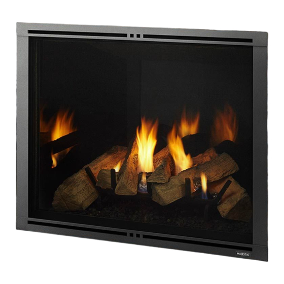
Decorative barrier front provided with this appliance.
HOT GLASS WILL
CAUSE BURNS.
UNTIL COOLED.
TO TOUCH GLASS.
1
Advertisement
Chapters
Table of Contents

Related Manuals for Majestic MARQ36IN-B


Summary of Contents for Majestic MARQ36IN-B
- Page 1 Decorative barrier front provided with this appliance. Majestic MARQ36IN-B, MARQ42IN-B Installation Manual • 2614-980 Rev. D • 4/19...
-
Page 2: Table Of Contents
B. Securing and Leveling the Appliance ....31 C. Installing Non-Combustible Facing Material ..32 = Contains updated information. Majestic MARQ36IN-B, MARQ42IN-B Installation Manual • 2614-980 Rev. D • 4/19... -
Page 3: Installation Standard Work Checklist
Comments: Further description of the issues, who is responsible (Installer/ Builder/ Other Trades, etc) and corrective action needed ____________________________________________________________________________________ Comments Communicated to party responsible ____________________ by ______________________on ___________ (Builder / Gen. Contractor/) (Installer) (Date) = Contains updated information. 2614-982 1/19 Majestic MARQ36IN-B, MARQ42IN-B Installation Manual • 2614-980 Rev. D • 4/19... -
Page 4: Product Specific And Important Safety Information
State of California to cause cancer and reproductive harm. For more information go to: www. P65Warnings.ca.gov. Majestic MARQ36IN-B, MARQ42IN-B Installation Manual • 2614-980 Rev. D • 4/19... -
Page 5: Requirements For The Commonwealth Of Massachusetts
VENT DIRECTLY BELOW. KEEP CLEAR OF ALL OB- of the installation. STRUCTIONS”. See Gas Connection section for additional Common- wealth of Massachusetts requirements. Majestic MARQ36IN-B, MARQ42IN-B Installation Manual • 2614-980 Rev. D • 4/19... -
Page 6: Getting Started
Wrenches Reciprocating saw 1/4 in. nut driver Non-corrosive leak check solution 1/2 - 3/4 in. length, #6 or #8 Self-drilling screws Caulking material (300 ºF minimum continuous exposure rating) Majestic MARQ36IN-B, MARQ42IN-B Installation Manual • 2614-980 Rev. D • 4/19... -
Page 7: Inspect Appliance And Components
DO NOT use this appliance if any part has been under water. Call a qualified service technician to inspect the appliance and to replace any part of the control system and/or gas control which has been under water. Majestic MARQ36IN-B, MARQ42IN-B Installation Manual • 2614-980 Rev. D • 4/19... -
Page 8: Framing And Clearances
Millimeters 1549 59-1/4 1505 35-7/8 39-7/8 1013 29-5/8 31-1/16 3-7/8 57-5/8 1464 2-3/4 35-3/16 10-7/8 34-3/16 16-1/8 54-15/16 1395 41-3/8 1051 16-7/8 25-5/8 23-1/2 Figure 3.1 Appliance Dimensions (MARQ36IN-B) Majestic MARQ36IN-B, MARQ42IN-B Installation Manual • 2614-980 Rev. D • 4/19... - Page 9 65-5/16 1659 41-7/8 1064 32-11/16 45-7/8 1165 3-7/8 36-1/16 2-3/4 62-5/8 1591 10-7/8 40-3/16 1021 16-1/8 39-3/16 59-15/16 1522 16-7/8 46-3/8 1178 30-5/8 23-1/2 Figure 3.2 Appliance Dimensions (MARQ42IN-B) Majestic MARQ36IN-B, MARQ42IN-B Installation Manual • 2614-980 Rev. D • 4/19...
- Page 10 (33 mm) MARQ42IN-B FSMQ42 40-9/16 IN. (1030 mm) 41-13/16 IN. (1062 mm) 46-11/16 IN. (1186 mm) 3-9/16 IN. 1-1/4 IN. (91 mm) (32 mm) Figure 3.3 Decorative Barrier Front Dimensions Majestic MARQ36IN-B, MARQ42IN-B Installation Manual • 2614-980 Rev. D • 4/19...
-
Page 11: Clearances To Combustibles
1/2 inch wall sheathing has not been installed. Inches 74-1/4 59-1/2 26-1/2 29-3/4 MARQ36IN-B Millimeters 1886 1511 2667 Inches 78-9/16 65-9/16 111-1/16 28-5/8 32-13/16 MARQ42IN-B Millimeters 1995 1665 2821 Figure 3.4 Appliance Locations Majestic MARQ36IN-B, MARQ42IN-B Installation Manual • 2614-980 Rev. D • 4/19... - Page 12 2 X 4 ONLY IN GRAY AREA NOTE: 2 X 4 HEADER CONFIGURATION 39 IN. 1 IN. FACTORY-SUPPLIED 1/2 IN. NON-COMBUSTIBLE BOARD 1/2 IN. = COMBUSTIBLES NOT ALLOWED Figure 3.5 Non-Combustible Zone Majestic MARQ36IN-B, MARQ42IN-B Installation Manual • 2614-980 Rev. D • 4/19...
-
Page 13: Constructing The Appliance Chase
See Sec- tion 3.D. Inches 9/16 MARQ42IN-B Millimeters 1549 1665 1321 * Adjust framing dimensions for interior sheathing (such as sheetrock) Figure 3.6 Clearances to Combustibles (2 X 4 Construction) Majestic MARQ36IN-B, MARQ42IN-B Installation Manual • 2614-980 Rev. D • 4/19... - Page 14 ** 2 x 4 material must be framed down from 2 x 6 rough opening height B’ to rough opening height B. Figure 3.7 Clearances to Combustibles (2 x 6 Construction) Majestic MARQ36IN-B, MARQ42IN-B Installation Manual • 2614-980 Rev. D • 4/19...
-
Page 15: Hearth Extension
WOOD OR OTHER COMBUSTIBLE FLOOR OR PLATFORM Figure 3.8 Non-Combustible Hearth Extension Dimensions Figure 3.10 Appliance Raised a Minimum of 3 Inches Above Combustible Surface. Non-Combustible Hearth Ex- tension NOT REQUIRED. Majestic MARQ36IN-B, MARQ42IN-B Installation Manual • 2614-980 Rev. D • 4/19... -
Page 16: Termination Location And Vent Information
Over 20/12 to 21/12 ..........8.0 * H minimum may vary depending on regional snowfall. Refer to local codes. Figure 4.3 Figure 4.1 Minimum Height From Roof to Lowest Discharge Opening Majestic MARQ36IN-B, MARQ42IN-B Installation Manual • 2614-980 Rev. D • 4/19... -
Page 17: Vent Terminal Clearances
24 in. (610 mm)* 24 in. (610 mm)* two sides beneath the floor.) Vinyl or composite overhang 42 in. (1067 mm) 42 in. (1067 mm) Figure 4.4 Minimum Clearances for Termination Majestic MARQ36IN-B, MARQ42IN-B Installation Manual • 2614-980 Rev. D • 4/19... -
Page 18: Use Of Elbows
• Horizontal terminations are measured to the outside mounting surface (flange of termination cap) (see Figure 4.3). • Vertical terminations are measured to bottom of termination cap. • Horizontal pipe installed level with no rise. Majestic MARQ36IN-B, MARQ42IN-B Installation Manual • 2614-980 Rev. D • 4/19... -
Page 19: Measuring Standards
• Horizontal pipe installed level with no rise. MEASURE TO SHADED SURFACE (OUTSIDE MOUNTING SURFACE) Figure 4.7 Measure to Outside Mounting Surface Figure 4.8 Measure to Top of Last Section of Pipe Majestic MARQ36IN-B, MARQ42IN-B Installation Manual • 2614-980 Rev. D • 4/19... -
Page 20: Vent Diagrams
40 ft 12.2 m After V = 6 ft then H = 2 x V ft Maximum = 60 ft Maximum *when used with approved termination caps Figure 4.9 Majestic MARQ36IN-B, MARQ42IN-B Installation Manual • 2614-980 Rev. D • 4/19... - Page 21 16 ft 4.9 m 9 ft 2.7 m 18 ft 5.5 m 10 ft 3.0 m 20 ft 6.1 m = 60 ft Maximum = 20 ft Maximum Figure 4.10 Majestic MARQ36IN-B, MARQ42IN-B Installation Manual • 2614-980 Rev. D • 4/19...
- Page 22 Shaded area of chart is for MARQ42IN-B (Propane) must be adhered to. has no specific restrictions EXCEPT, = 2 x V and V cannot exceed 60 ft Maximum t max total total Figure 4.11 Majestic MARQ36IN-B, MARQ42IN-B Installation Manual • 2614-980 Rev. D • 4/19...
- Page 23 See Figure 4.14. EXHAUST RESTRICTOR SET TO 2-2 3. Orientate and align the two pieces of the exhaust Figure 4.14 Exhaust Restrictor Installation restrictor as shown in Figure 4.14. Majestic MARQ36IN-B, MARQ42IN-B Installation Manual • 2614-980 Rev. D • 4/19...
-
Page 24: Shaded Area Of Chart Is For Marq42In-B (Propane)
Shaded area of chart is for MARQ42IN-B (Propane) *No specific restrictions on this value EXCEPT = 50 ft (15.2 m) Max. After V = 6 ft, then H Max.= V Figure 4.15 Majestic MARQ36IN-B, MARQ42IN-B Installation Manual • 2614-980 Rev. D • 4/19... - Page 25 EXCEPT, after V = 6 ft, then H Max = 2 x V TOTAL = 50 ft (15.2 m) Max. TOTAL + TOTAL INSTALLED HORIZONTALLY Figure 4.16 Majestic MARQ36IN-B, MARQ42IN-B Installation Manual • 2614-980 Rev. D • 4/19...
-
Page 26: Pvlp-Slp And Pvi-Slp-B Information
Figure 4.18 Baffle Adjustment - PVI-SLP-B Allowable Baffle Distance from PVLP-SLP to Appliance Minimum Maximum 2-15 ft. 1-1/2 in. 2-1/2 in. 16-39 ft. Closed 1-1/2 in. Greater than 40 Closed Table 4.2 Majestic MARQ36IN-B, MARQ42IN-B Installation Manual • 2614-980 Rev. D • 4/19... -
Page 27: Vent Clearances And Framing
(refer to Section 12.A.) attached to them. • See Section 7.E. for information for regarding the instal- lation of a horizontal termination cap. Majestic MARQ36IN-B, MARQ42IN-B Installation Manual • 2614-980 Rev. D • 4/19... -
Page 28: Ceiling Firestop/Floor Penetration Framing
INSTALL ATTIC INSULATION SHIELDS BEFORE OR AFTER INSTALLATION OF VENT SYSTEM CEILING FIRESTOP CEILING FIRESTOP INSTALLED BELOW CEILING INSTALLED ABOVE CEILING Figure 5.4 Installing the Attic Shield Majestic MARQ36IN-B, MARQ42IN-B Installation Manual • 2614-980 Rev. D • 4/19... -
Page 29: Installing The Optional Heat-Zone ® Gas Kit
• Determine the location for the air register/fan housing assembly. Reference the Heat-Zone Gas Kit instructions for the ® remaining installation steps. HEAT ZONE LOCATION ® LEFT AND RIGHT SIDES Figure 5.5 Heat Zone Cover Plate Majestic MARQ36IN-B, MARQ42IN-B Installation Manual • 2614-980 Rev. D • 4/19... -
Page 30: Appliance Preparation
Gasket is installed at the factory. LOGS SEAL CAP FINISHING TEMPLATES SPLATTER GUARD HEADER HEAT SHIELDS TECO-SIL (SHIPPED ON REAR SIDE OF APPLIANCE Figure 6.1 Shipping Location of Components Majestic MARQ36IN-B, MARQ42IN-B Installation Manual • 2614-980 Rev. D • 4/19... -
Page 31: Securing And Leveling The Appliance
• Secure the appliance to the floor by inserting two screws through the pilot holes at the bottom of the appliance. Figure 6.5. Heat Shields and Nailing Tabs in Installation Position Majestic MARQ36IN-B, MARQ42IN-B Installation Manual • 2614-980 Rev. D • 4/19... -
Page 32: Installing Non-Combustible Facing Material
• Use a wet or dry towel or soft brush to remove dust or dirt from facing material. • See Section 10 for finishing materials guidelines. Figure 6.7 Installing Non-Combustible Facing Material Figure 6.6 Shipping Location of Non-Combustible Board Majestic MARQ36IN-B, MARQ42IN-B Installation Manual • 2614-980 Rev. D • 4/19... -
Page 33: Venting And Chimneys
• Only outer pipes need to be sealed. All unit collar, pipe, slip section, elbow and cap outer flues shall be sealed in this manner, unless otherwise stated. Majestic MARQ36IN-B, MARQ42IN-B Installation Manual • 2614-980 Rev. D • 4/19... -
Page 34: Assemble Slip Sections
• Continue adding pipe as necessary following instructions in “Assembling Pipe Sections.” NOTICE: If slip section is too long, the inner and outer flues of the slip section can be cut to the desired length. Majestic MARQ36IN-B, MARQ42IN-B Installation Manual • 2614-980 Rev. D • 4/19... -
Page 35: Secure The Vent Sections
Figure 7.9 Rotate Seams for Disassembly connection point to appliance. 120º Figure 7.10 Align and Disassemble Vent Sections Figure 7.7 Securing Vertical Pipe Sections 120º Figure 7.8 Securing Horizontal Pipe Sections Majestic MARQ36IN-B, MARQ42IN-B Installation Manual • 2614-980 Rev. D • 4/19... -
Page 36: Vertical Termination Requirements
See Figure 7.12. • Tighten nut and make sure the collar is tight against the pipe section. • Seal around the top of the storm collar. See Figure 7.13. Figure 7.11 Majestic MARQ36IN-B, MARQ42IN-B Installation Manual • 2614-980 Rev. D • 4/19... -
Page 37: Horizontal Termination Requirements
• Rest the small leg on the extended heat shield on top of the pipe section to properly space it from the pipe section. Important Notice: Heat shields may not be field constructed. Figure 7.13 Venting through the wall Majestic MARQ36IN-B, MARQ42IN-B Installation Manual • 2614-980 Rev. D • 4/19... - Page 38 Figure 7.14 Venting Through the Wall resistance to wind-driven rain penetration, a flashing kit and HRC caps are available. When penetrating a brick wall, a brick extension kit is available for framing the brick. Majestic MARQ36IN-B, MARQ42IN-B Installation Manual • 2614-980 Rev. D • 4/19...
-
Page 39: Electrical Information
ACCESS THROUGH LEFT COLUMN ACCESS THROUGH FIREBOX (Prior to installation of non-combustible board) (After installation of non-combustible board) GASKET COVER Figure 8.1 Junction Box Access Majestic MARQ36IN-B, MARQ42IN-B Installation Manual • 2614-980 Rev. D • 4/19... - Page 40 Verify proper operation after servicing. WARNING! Risk of Shock! Replace damaged wire with type 105º C rated wire. Wire must have high temperature insulation. Majestic MARQ36IN-B, MARQ42IN-B Installation Manual • 2614-980 Rev. D • 4/19...
-
Page 41: Wiring Requirements
RF MODULE GRN/WHT/BLK 6 PIN CONTROL RED/BLK RED/BLK SPLITTER 6V DC BATTERY PACK APPLIANCE ON/OFF CONTROL BLACK/RED REAR ACCENT LIGHTING (X 2) Figure 8.3 IFT Wiring Diagram without Power Vent Majestic MARQ36IN-B, MARQ42IN-B Installation Manual • 2614-980 Rev. D • 4/19... - Page 42 GRN/WHT/BLK 6 PIN CONTROL RED/ RED/ ACCESSORY CABLE POWER VENT (OPTIONAL) (PVI-SLP-B SHOWN) JUMPER WIRE BLACK/RED REAR ACCENT LIGHTING (X 2) Figure 8.4 IFT Wiring Diagram with Power Vent Majestic MARQ36IN-B, MARQ42IN-B Installation Manual • 2614-980 Rev. D • 4/19...
-
Page 43: Gas Information
1/2 in. (13 Check with your local gas utility to determine proper mm) control valve inlet. orifice size. • If substituting for these components, please consult local codes for compliance. Majestic MARQ36IN-B, MARQ42IN-B Installation Manual • 2614-980 Rev. D • 4/19... -
Page 44: Air Shutter Setting
This is due to the different chemical compositions that make up both fuel types. In general, the Propane flames may be a little shorter and much brighter than a natural gas flame. Majestic MARQ36IN-B, MARQ42IN-B Installation Manual • 2614-980 Rev. D • 4/19... -
Page 45: Finishing
NOTICE: Surface temperatures around the appliance will become warm while the appliance is in operation. Ensure finishing materials used for all surfaces (floor, walls, mantels, etc.) will withstand temperatures up to 190°F. Majestic MARQ36IN-B, MARQ42IN-B Installation Manual • 2614-980 Rev. D • 4/19... -
Page 46: Finishing Templates
Follow the glass removal instructions in Section TOP FINISHING TEMPLATE SIDE FINISHING TEMPLATES Figure 10.4 Top and Side Finishing Template Locations 1-1/4 IN. Figure 10.2 Top Finishing Template Bend Majestic MARQ36IN-B, MARQ42IN-B Installation Manual • 2614-980 Rev. D • 4/19... - Page 47 Note: A thin layer of mortar may be applied over the visible non-combustible board between finishing material and the fireplace opening. Figure 10.5 Finishing Template Bends Majestic MARQ36IN-B, MARQ42IN-B Installation Manual • 2614-980 Rev. D • 4/19...
-
Page 48: Mantel And Wall Projections
6 IN. MAX. SEE SECTION 10.D FACTORY-SUPPLIED FOR REQUIRED NON-COMBUSTIBLE CLEARANCES BOARD 14 IN. MIN. COMBUSTIBLE OR FIREPLACE NON-COMBUSTIBLE OPENING WALL Figure 10.7 Non-Combustible Mantel Leg and Wall Projections Majestic MARQ36IN-B, MARQ42IN-B Installation Manual • 2614-980 Rev. D • 4/19... - Page 49 = 40-3/16 IN. (MARQ42IN-B) MARQ42IN-B MARQ42IN-B MIN. 1-1/4 IN. FIREPLACE FIREPLACE OPENING OPENING Figure 10.11 Combustible Mantel Allowance - MARQ42IN-B Figure 10.12 Non-Combustible Mantel Allowance - MARQ42IN-B Majestic MARQ36IN-B, MARQ42IN-B Installation Manual • 2614-980 Rev. D • 4/19...
-
Page 50: Decorative Barrier Front Dimensions For Finishing
NOTICE: Proper clearances from the fireplace opening to any finishing material thicker than 1 inch MUST be maintained. NOTE: Finishing templates are included with this product. See Section 10.B. Majestic MARQ36IN-B, MARQ42IN-B Installation Manual • 2614-980 Rev. D • 4/19... -
Page 51: Appliance Setup
CAUTION! Risk of Injury! DO NOT put fingers under glass frame. Fingers may get pinched by glass frame during removal. Figure 11.1. Glass Clip Tool Majestic MARQ36IN-B, MARQ42IN-B Installation Manual • 2614-980 Rev. D • 4/19... - Page 52 CAUTION! Risk of Injury! DO NOT put fingers under glass frame. Fingers may get pinched by glass frame during installation. Figure 11.8. Securing Bottom Glass Clips Majestic MARQ36IN-B, MARQ42IN-B Installation Manual • 2614-980 Rev. D • 4/19...
-
Page 53: Remove The Shipping Materials
Figure 11.10. Location of Glowing Embers in Shaded Areas refractory pieces. Figure 11.9. Apply Lava Rock Majestic MARQ36IN-B, MARQ42IN-B Installation Manual • 2614-980 Rev. D • 4/19... -
Page 54: Teco-Sil Placement
• Spread Teco-Sil evenly over bottom glass assembly. See Figure 11.11 • Turn ember lights on and fog Teco-Sil to desired coverage. See Figure 11.12. Figure 11.11. Teco-Sil Placement Figure 11.12. Teco-Sil Fogged Majestic MARQ36IN-B, MARQ42IN-B Installation Manual • 2614-980 Rev. D • 4/19... -
Page 55: Log Set Assembly
The numbers are listed in parentheses above. NOTE: Interior of MARQ36IN is shown in log installation pictures. Instructions apply to both the MARQ36IN and MARQ36IN-B. Figure 1. Log Set Majestic MARQ36IN-B, MARQ42IN-B Installation Manual • 2614-980 Rev. D • 4/19... - Page 56 Log #2 (2270-703): Log #2 is positioned on the front left grate using groove depicted in Figure 5. Ensure the log is slid forward to bend in grate tine. The log also mates with the center grate tine using feature shown in Figure 5. Majestic MARQ36IN-B, MARQ42IN-B Installation Manual • 2614-980 Rev. D • 4/19...
- Page 57 Log #5 (2270-706) : Position Log #5 on top of the center grate tine and interlock with the right front grate tine, mating with the recess on Log #4. See Figure 12 & 13. Majestic MARQ36IN-B, MARQ42IN-B Installation Manual • 2614-980 Rev. D • 4/19...
- Page 58 Log #1 and Log #5. Log #7 will rest on the top of Log #2 and mate with the middle grate tine. See Figure 16. Figure 16. Log Set Installed Majestic MARQ36IN-B, MARQ42IN-B Installation Manual • 2614-980 Rev. D • 4/19...
- Page 59 The numbers are listed in parentheses above. NOTE: Interior of MARQ42IN is shown in log installation pictures. Instructions apply to both the MARQ42IN and MARQ42IN-B. Figure 1. Log Set Majestic MARQ36IN-B, MARQ42IN-B Installation Manual • 2614-980 Rev. D • 4/19...
-
Page 60: Log #2 - 2271-703
Log #2 (2271-703): Position Log #2 on the front left grate using groove shown in Figure 5. Ensure the log is slid forward to bend in the grate tine. The log will also mate with the center grate tine using feature shown in Figure 5. Majestic MARQ36IN-B, MARQ42IN-B Installation Manual • 2614-980 Rev. D • 4/19... -
Page 61: Log #3 - 2271-702
Log #4 (2271-704): See bottom of Log #4 in Figure 10. The two grooves will mate with the grate tines as shown in Figure 11. The log will contact the base refractory, side refractory panel, and the tip of Log #1, creating 5 total contact points. Majestic MARQ36IN-B, MARQ42IN-B Installation Manual • 2614-980 Rev. D • 4/19... -
Page 62: Log #5 - 2271-706
Log #1 and Log #5. Log #7 will rest on top of Log #2 and mate with middle grate. See Figure 17. Figure 17. Log Set Installed. Majestic MARQ36IN-B, MARQ42IN-B Installation Manual • 2614-980 Rev. D • 4/19... -
Page 63: Intellifire™ Touch Control System Setup
4. Wait to verify LED indicator on the ECM stops flash- ing. 5. Install batteries in the RC400 remote. 6. The RC400 remote will automatically pair to the appli- ance as pre-set at the factory. Majestic MARQ36IN-B, MARQ42IN-B Installation Manual • 2614-980 Rev. D • 4/19... -
Page 64: Reference Materials
(356 MM) (508 MM) 6 in. 14 IN. (152 mm) (356 MM) 12 IN. (305 MM) DVP-WS (Wall Shield Firestop) DVP-RDS ROOF DECK INSULATION SHIELD Figure 12.1 DVP vent components Majestic MARQ36IN-B, MARQ42IN-B Installation Manual • 2614-980 Rev. D • 4/19... - Page 65 (305 mm) 79 mm 117 mm Length DVP-TRAP 5-3/8 in. 9-3/8 in. Trap2 Horizontal Termination Cap 137 mm 238 mm DVP-TRAP2 DVP-TRAP1 DVP-TRAPK2 DVP-TRAPK1 Figure 12.2 DVP vent components Majestic MARQ36IN-B, MARQ42IN-B Installation Manual • 2614-980 Rev. D • 4/19...
- Page 66 13-7/8 in. 9-1/2 in. Cap Shield (352 mm) (241 mm) 26 in. 660 mm 14 in. (356 mm) DVP-HSM-B Extended Heat Shield DRC-RADIUS Cap Shield Figure 12.3 DVP Vent Components Majestic MARQ36IN-B, MARQ42IN-B Installation Manual • 2614-980 Rev. D • 4/19...
- Page 67 9-3/16 IN. (233 mm) 13-5/8 IN. 16-11/16 IN. 16-11/16 IN. (346 mm) 424 mm (424 mm) 12-1/2 IN. SLP-LPC (318 mm) SLP Low Profile Cap Figure 12.4 DVP vent components Majestic MARQ36IN-B, MARQ42IN-B Installation Manual • 2614-980 Rev. D • 4/19...
- Page 68 Option A: IFT-RC400 or Option B: IFT-RC150, IFT-ACM. These accessories are purchased separately from the PVLP- SLP. Contact your dealer to order. PVLP-HS PVLP-BEK Heat Shield Brick Kit Figure 12.5 PVLP-SLP Vent Components Majestic MARQ36IN-B, MARQ42IN-B Installation Manual • 2614-980 Rev. D • 4/19...
-
Page 69: Accessories
Street West, Lakeville, MN 55044 www.majesticproducts.com Please contact your Majestic dealer with any questions or concerns. For the location of your nearest Majestic dealer, please visit www.majesticproducts.com. Printed in U.S.A. - Copyright 2019 Majestic MARQ36IN-B, MARQ42IN-B Installation Manual • 2614-980 Rev. D • 4/19...