Table of Contents
Advertisement
Quick Links
TECHNICAL MANUAL
Of
Intel Q170 Express Chipset
Based Mini-ITX M/B
NO. G03-NF795-F
Revision: 2.0
Release date: October 1, 2019
Trademark:
* Specifications and Information contained in this documentation are furnished for information use only, and are
subject to change at any time without notice, and should not be construed as a commitment by manufacturer.
Advertisement
Table of Contents

Related Manuals for JETWAY NF795-Q170


Summary of Contents for JETWAY NF795-Q170
- Page 1 TECHNICAL MANUAL Intel Q170 Express Chipset Based Mini-ITX M/B NO. G03-NF795-F Revision: 2.0 Release date: October 1, 2019 Trademark: * Specifications and Information contained in this documentation are furnished for information use only, and are subject to change at any time without notice, and should not be construed as a commitment by manufacturer.
- Page 2 Environmental Protection Announcement Do not dispose this electronic device into the trash while discarding. To minimize pollution and ensure environment protection of mother earth, please recycle.
-
Page 3: Table Of Contents
TABLE OF CONTENT ENVIRONMENTAL SAFETY INSTRUCTION ..............iii USER’S NOTICE ........................iv MANUAL REVISION INFORMATION .................. iv ITEM CHECKLIST ........................ iv CHAPTER 1 INTRODUCTION OF THE MOTHERBOARD FEATURE OF MOTHERBOARD ................1 SPECIFICATION ......................2 LAYOUT DIAGRAM ....................3 CHAPTER 2 HARDWARE INSTALLATION JUMPER SETTING ..................... -
Page 4: Environmental Safety Instruction
Environmental Safety Instruction Avoid the dusty, humidity and temperature extremes. Do not place the product in any area where it may become wet. 0 to 40 centigrade is the suitable temperature. (The temperature comes from the request of the chassis and thermal solution) ... -
Page 5: User's Notice
USER’S NOTICE COPYRIGHT OF THIS MANUAL BELONGS TO THE MANUFACTURER. NO PART OF THIS MANUAL, INCLUDING THE PRODUCTS AND SOFTWARE DESCRIBED IN IT MAY BE REPRODUCED, TRANSMITTED OR TRANSLATED INTO ANY LANGUAGE IN ANY FORM OR BY ANY MEANS WITHOUT WRITTEN PERMISSION OF THE MANUFACTURER. -
Page 6: Chapter 1 Introduction Of The Motherboard
Chapter 1 Introduction of the Motherboard Feature of Motherboard ® Intel Q170 express chipset ® Support LGA 1151 CPU socket for the 6 & 7 CPU Intel Core™ i7 / i5 i3 processors / Pentium™ & Celeron™ processors (TDP ≤65 W). ... -
Page 7: Specification
1-2 Specification Spec Description Thin mini-ITX form factor; 8-layer; PCB size: 17.0x17.0cm Design Intel Q170 Express Chipset Chipset ® Intel LGA 1151 Socket for Skylake & kabylack series processors: 6 & 7 Core™ i7/ i5/ i3, Pentium™ & Celeron™ CPU Socket processors * for detailed CPU support information please visit our website... -
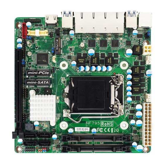
Page 8: Layout Diagram
1* Front panel header 1* 9-Pin USB 2.0 header for 2* USB 2.0 ports 1* 19-Pin USB 3.0 header for 2* USB3.0 ports 1 * PS2 Keyboard & Mouse header 1* LAN Status LED header ... - Page 9 Motherboard Internal Diagram-Front ATX Type Main Power Connector SYS FAN Connector CPUFAN Connector RJ-45 COM Port ATX 12V Power Connector USB 3.0 Ports DDR4 SODIMM Slots (SODIMM1/SODIMM2) RJ-45 LAN Ports (LAN1) LGA 1151 CPU Socket M.2 PCIE Slot (M2E) USB 3.0 Ports Full-size LAN_LED MSATA Slot (MSATA)
- Page 10 Internal Diagram-Back Side: SIM Card Slot *Note: 1.SIM card slot (BSIMCARD) only works when compatible SIM card installed & USB 3G expansion card installed in the full-size MSATA slot (MSATA); 2. USB 3G card and MSATA card is optional, i.e., user can only choose one to installed in the full-size MSATA at the same time.
- Page 11 Motherboard Jumper Position JPCOM1 JPM2E AT_MODE *JP2 JBAT JPLCD JPBKLT JPMPE COPEN *Note: JP2 is for RMA test only.
- Page 12 Connectors Name RJ45_COM1 RJ-45 COM Port Connector for Console USB1/USB2 USB 3.0 Port Connector X4 LAN1 RJ-45 LAN Connector X4 HDMI HDMI Port Connector ATXPWR Main Power Connector ATX12V Internal 12V Power Connector SATA1/2/3/4 SATAIII Connector CPUFAN CPUFAN Connector SYSFAN SYFFAN Connector Headers Name...
-
Page 13: Chapter 2 Hardware Installation
Jumper Name Description JPCOM1 RJ45_COM1 Port VCC 5V/12V Select 4-pin Block JBAT Clear CMOS Setting 2-pin Block COPEN Case Open Message Display Function Select 2-pin Block AT_MODE AT/ATX Mode Select 3-Pin Block JPLCD LVDS Panel VCC 3.3V/5V/12V Select 4-pin Block JPBKLT LVDS Backlight VCC 5V/12V Select 3-pin Block... - Page 14 JBAT (2-pin): Clear CMOS Settings → JBAT Clear CMOS JBAT Pin1 1-2 Open: Normal; Pin1 1-2 Closed: Clear CMOS. COPEN (2-pin): Case Open Message Display Function Select → COPEN Case Open Detection Pin1 COPEN Pin 1-2 Short: When Case open function pin short to GND, the Case open function was detected.
- Page 15 AT_MODE (3-pin): AT Mode /ATX Mode Select AT_MODE → AT_MODE ATX/AT Mode Select 1-2 Closed: ATX Mode Selected; 2-3 Closed: AT Mode Selected. *ATX Mode Selected: Press power button to power on after power input ready; AT Mode Selected: Directly power on as power input ready. JPLCD (4-pin): LVDS VCC 3.3V/5V/12V Select JPLCD →...
- Page 16 JPBKLT (3-pin): LVDS Inverter Backlight VCC Select → JPBKLT Inverter Backlight VCC Select JPBKLT 1-2 Closed: Inverter 5V Selected; 2-3 Closed: Inverter 12V Selected. JPMPE (3-pin): Mini PCI-E (MPE) Slot VCC 3.3V/3.3 VSB Select → JPMEP MPE Slot VCC Select JPMPE 1-2 Closed: MPE VCC= VCC3V;...
- Page 17 JPM2E (3-pin): M.2 PCIe (M2E) Slot VCC 3.3V/3.3 VSB Select → JPM2E M2E Slot VCC Select JPM2E 1-2 Closed: M2E Slot VCC= VCC3V; 2-3 Closed: M2E Slot VCC=3VSB. JP1(2-pin): DFDS Override Select → DFDS Override Pin1 1-2 Open: Normal(Default); Pin1 1-2 Closed: Disable Flash Descriptor Security (override).
-
Page 18: Connectors And Headers
Connectors and Headers 2-2-1 Connectors (1) RJ45_COM1(8-pin block): RJ-45 COM Port Connector for Console (2) ATXPWR(24-pin block): Main Power Connector... - Page 19 (3) ATX12V (4-pin block): 12V Internal Power Connector (4) SATA1/2/3/4 (7-pin): SATA III Port connector These are high-speed SATAIII port that supports 6 GB/s transfer rate. SATA3 SATA2 Pin No. Definition SATA4 SATA1...
-
Page 20: Headers
(5) SYSFAN/CPUFAN (4-pin): Fan Connectors CPUFAN1 SYSFAN 2-2-2 Headers (1) JW_FP (9-pin): Front Panel Header JW_FP RSTSW PWRBTN PWRLED- HDDLED- HDDLED+ PWRLED+ Pin 1... - Page 21 (2) SKEAKER (4-pin): Speaker Header Pin 1 SPEAKER (3) FP_USB1 (9-pin): USB 2.0 Port Header +DATA +DATA -DATA -DATA FP USB1 Pin 1...
- Page 22 (4) FP_USB31 (9-pin): USB 2.0 Port Header SSTX2+ FP_USB31 SSTX2- SSTX1+ SSTX1- SSRX2+ SSRX1+ SSRX2- SSRX1- VBUS VBUS Pin 1 (5) PS2KBMS (6-pin): PS/2 Keyboard & Mouse Header PS2KBMS Pin1...
- Page 23 (6) LAN_LED (8-pin): LANLED Header LAN_LED Pin1 (7) GPIO_CON (10-pin): GPIO Header Pin1 GPIO_CON...
- Page 24 (8) LVDS2 (30-Pin): 24-bit dual channel LVDS Header LVDS2 Pin 1 Pin 2 Pin NO. Pin Define Pin NO. Pin Define Pin 1 LVDSB_DATAN3 Pin 2 LVDSB_DATAP3 Pin 3 LVDS_CLKBN Pin 4 LVDS_CLKBP Pin 5 LVDSB_DATAN2 Pin 6 LVDSB_DATAP2 Pin 7 LVDSB_DATAN1 Pin 8 LVDSB_DATAP1...
- Page 25 (9) INVERTER2 (8-pin): LVDS Inverter Connector Pin No. Definition Backlight Enable Backlight PWM PVCC PVCC Backlight Up SW Pin1 Backlight Down SW INVERTER Warning! Find Pin-1 location of the inverter and make sure that the installation direction is correct! Otherwise serious harm will occur to the board/display panel!!
-
Page 26: Chapter 3 Introducing Bios
Chapter 3 Introducing BIOS Notice! The BIOS options in this manual are for reference only. Different configurations may lead to difference in BIOS screen and BIOS screens in manuals are usually the first BIOS version when the board is released and may be different from your purchased motherboard. Users are welcome to download the latest BIOS version form our official website. -
Page 27: Bios Menu Screen
BIOS Menu Screen The following diagram show a general BIOS menu screen: Menu Bar General Help Items Current Setting Value Menu Items Function Keys BIOS Menu Screen Function Keys In the above BIOS Setup main menu of, you can see several options. We will explain these options step by step in the following pages of this chapter, but let us first see a short description of the function keys you may use here: ... -
Page 28: Getting Help
Press <+>/<–> keys when you want to modify the BIOS parameters for the active option. [F1]: General help. [F2]: Previous values. [F3]: Optimized defaults. [F4]: Save & Exit. Press <Esc> to exit from BIOS Setup. Getting Help Main Menu The on-line description of the highlighted setup function is displayed at the top right... -
Page 29: Main Menu
Main Menu Main menu screen includes some basic system information. Highlight the item and then use the <+> or <-> and numerical keyboard keys to select the value you want in each item. System Date Set the date. Please use [Tab] to switch between data elements. System Time Set the time. -
Page 30: Advanced Menu
3-7 Advanced Menu CPU Configuration Press [Enter] to view current CPU configuration and make settings for the following sub-items: Hyper-Threading The optional settings: [Disabled]; [Enabled]. When set as [Disabled] only one thread per enabled core is enabled. [Enabled]: for Windows and Linux (OS optimized for Hyper-Threading Technology). - Page 31 The optional settings: [Disabled]; [Enabled]. Adjacent Cache Line Prefetch Use this item to turn on/off prefeching of adjacent cache lines. The optional settings: [Disabled]; [Enabled]. Intel(R) SpeedStep(tm) This item allows more than two frequency ranges to be supported. The optional settings: [Disabled]; [Enabled]. CPU C Status Use this item to enable or disable CPU C status.
- Page 32 mSATA Port Use this item to enable or disable device connected to MSATA port. The optional settings: [Disabled]; [Enabled]. PCH-FW Configuration Press [Enter] to view Management Engine technology parameters and make settings in the following sub-items: TPM Device Selection Use this item to select TPM device.
- Page 33 Configuration Prompt function. The optional settings: [Disabled]; [Enabled]. MEBx Debug Message Output Use this function to enable or disable MEBx Debug Message Output function. The optional settings: [Disabled]; [Enabled]. Un-Configure ME Use this function to enable or disable Un-Configure ME without password function. The optional settings: [Disabled];...
- Page 34 Use this item to enable or disable BIOS support for security device. O.S. will not show security device. TGG EFI protocol and INT1A interface will not be available. The optional settings: [Disabled]; [Enabled]. *When set as [Enabled], user can make further settings in the following items: TPM State Use this item to enable or disable security device.
- Page 35 The optional settings: [Enabled]; [Disabled]. Use this item to enable or disable PS2 KB/MS wake-up from S3/S4/S5 or USB from S3/S4 state. *This function is supported when ‘ERP Support’ is set as [Disabled]. USB S5 Power Use this item to enable or disable USB power after power shutdown. *This function is supported when ‘ERP Support’...
- Page 36 This item support WDT wake-up while ‘ERP Support’ is set as [Auto]. The optional settings: [Disabled]; [Enabled]. When set as [Enabled], the following sub-items shall appear: WatchDog Timer Value in ERP User can select a value in the range of [10] to [4095] seconds when ‘WatchDog Reset Timer Unit in ERP’...
- Page 37 Use this item to set CPUFAN /SYSFAN1 full speed temperature. Fan will run at full speed when above this pre-set temperature. CPUFAN / SYSFAN1 Full-Speed Duty Use this item to set CPUFAN/SYSFAN1 full-speed duty. Fan will run at full speed when above this pre-set duty.
- Page 38 matched on the other side. Long or noisy lines may require lower speeds. The optional settings: [9600]; [19200]; [38400]; [57600]; [115200]. Data Bits The optional settings: [7]; [8]. Parity A parity bit can be sent with the data bits to detect some transmission errors. The optional settings: [None];...
- Page 39 The optional settings: [80x24]; [80x25]. Putty KeyPad Use this item to select FunctionKey and KeyPad on Putty. The optional settings: [VT100]; [Linux]; [XTERMR6]; [SCO]; [ESCN]; [VT400]. Redirection After BIOS POST The optional settings are: [Always Enable]; [BootLoader]. Whet Bootloader is selected, then Lagacy Console Redirection is disabled before booting to legacy OS.
- Page 40 The optional settings: [9600]; [19200]; [57600]; [115200]. Flow Control Flow control can prevent data loss from buffer overflow. When sending data, if the receiving buffers are full, a “stop” signal can be sent to stop the data flow. Once the buffers are empty, a “start” signal can be sent to re-start the flow. Hardware flow control uses two wires to send start/stop signals.
- Page 41 option will not be created. Ipv6 HTTPE Support The optional settings are: [Disabled]; [Enabled]. Use this item to enable Ipv6 HTTP Boot Support. When set as [Disabled], Ipv6 HTTP boot option will not be created. PXE boot wait time Use this item to set wait time to press [ESC] key to abort the PXE boot. Media Detect Count Use this item to set number of times presence of media will be checked.
- Page 42 ownership change should be claimed by XHCI driver. The optional settings are: [Enabled]; [Disabled]. USB Mass Storage Driver Support Use this item to enable or disable USB mass storage driver support. The optional settings are: [Disabled]; [Enabled]. USB hardware delay and time-out USB Transfer time-out Use this item to set the time-out value for control, bulk, and interrupt transfers.
-
Page 43: Chipset Menu
3-8 Chipset Menu System Agent (SA) Configuration Press [Enter] to make settings for the following sub-items: VT-d The optional settings are: [Enabled]; [Disabled]. ► Graphics Configuration Press [Enter] to make further settings for Graphics Configuration. Graphics Configuration Primary Display Use this item to select which of IGFX/PEG/PCI graphics device should be Primary Display. - Page 44 GTT Size The optional settings are: [2MB]; [4MB]; [8MB]. Aperture Size The optional settings are: [128MB]; [256MB]; [512MB]; [1024MB]. *Note: above 4GB MMIO BIOS assignment is automatically enabled when selecting 2048MB aperture. To use this feature, please disable CSM Support. DVMT Pre-Allocated Use this item to select DVMT 5.0 pre-allocated (fixed) graphics memory size used by the internal graphics device.
- Page 45 Panel Type Use this item to select Panel Type. The optional settings are: [800x480 18bit Single]; [800x600 18bit Single]; [800x600 24bit Single]; [1024x600 18bit Single]; [1024x768 18bit Single]; [1024x768 24bit Single]; [1280x768 24bit Single]; [1280x800 18bit Single]; [1280x800 24bit Single]; [1366x768 18bit Single]; [1366x768 24bit Single]; [1440x900 18bit Dual];...
-
Page 46: Security Menu
MPE Slot Use this item to enable or disable MPE slot device or controller. The optional settings are: [Disabled]; [Enabled]. Speed The optional settings are: [Auto]; [Gen1]; [Gen2]; [Gen3]. M2E Slot Use this item to enable or disable M2E slot device or controller. The optional settings are: [Disabled];... -
Page 47: Boot Menu
Security menu allow users to change administrator password and user password settings. Administrator Password Press [Enter] to create new administrator password. Press again to confirm the new administrator password. User Password Press [Enter] to create new user password. Press again to confirm the new user password. -
Page 48: Save & Exit Menu
The optional settings are: [On]; [Off]. Quiet Boot The optional settings are: [Disabled]; [Enabled]. Boot Option Priorities Boot Option #1/ Boot Option #2… Use this item to decide system boot order from available options. 3-11 Save & Exit Menu Save Options Save Changes and Reset This item allows user to reset the system after saving the changes. - Page 49 Use this item to save the changes done so far as user defaults. Restore User Defaults Use this item to restore the user defaults to all the setup options. Boot Override UEFI: Built-in EFI Shell Press this item and a dialogue box shall appear to ask if user wish to save configuration and reset.