Table of Contents

Related Manuals for Samsung AM NN1DEH Series


Summary of Contents for Samsung AM NN1DEH Series
- Page 1 Air conditioner User manual AM***NN1PEH*** / AM***NN1DEH*** / AM***NN1DKH*** Thank you for purchasing this Samsung air conditioner. Before operating this unit, please read this user manual carefully and retain it for future reference.
-
Page 2: Table Of Contents
Business users should contact their supplier and check the terms and conditions of the purchase contract. This product and its electronic accessories should not be mixed with other commercial wastes for disposal. For information on Samsung’s environmental commitments and product-specific regulatory obligations, e.g. REACH, WEEE, Batteries, visit: www.samsung.com/uk/aboutsamsung/sustainability/environment/our-commitment/data/... -
Page 3: Safety Information
If you have any questions, call your nearest contact centre or find help and information online at www.samsung.com. WARNING Hazards or unsafe practices that may result in severe personal injury or death. - Page 4 Safety Information Safety Information The installation of this appliance must be performed by a qualified technician or service company. Failing to do so may result in electric shock, fire, explosion, problems with the product, or injury. Install a switch and circuit breaker dedicated to the air conditioner. Failing to do so may result in electric shock or fire.
- Page 5 When installing the outdoor unit, make sure to connect the drain hose so that draining is performed correctly. The water generated during the heating operation in the outdoor unit may overflow and result in property damage. In particular, in winter, if a block of ice falls, it may result in injury, death or property damage.
- Page 6 Safety Information Safety Information In the event of a gas leak (such as propane gas, LP gas, etc.), ventilate immediately without touching the power line. Do not touch the appliance or power line. Do not use a ventilating fan. A spark may result in an explosion or fire. To reinstall the air conditioner, please contact your nearest service centre.
- Page 7 Do not insert your fingers or foreign substances into the air inlet/outlet of the air conditioner. Take special care that children do not injure themselves by inserting their fingers into the product. Do not strike or pull the air conditioner with excessive force. This may result in fire, injury, or problems with the product.
- Page 8 Safety Information Safety Information Do not stand on top of the appliance or place objects (such as laundry, lighted candles, lighted cigarettes, dishes, chemicals, metal objects, etc.) on the appliance. This may result in electric shock, fire, problems with the product, or injury. Do not operate the appliance with wet hands.
- Page 9 For use in Europe: This appliance can be used by children aged from 8 years and above and persons with reduced physical, sensory or mental capabilities or lack of experience and knowledge if they have been given supervision or instruction concerning use of the appliance in a safe way and understand the hazards involved.
-
Page 10: At A Glance
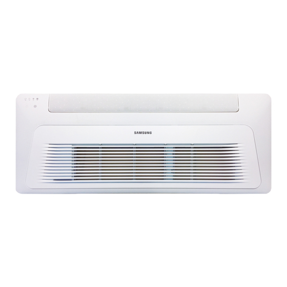
Indoor Unit Overview Indoor Unit Overview Main parts The indoor unit and its display may look slightly different from the illustration shown below, depending on the model and the panel type. PC1*WFMAN / PC1*WCMAN 01 Display Indication Function Operation indicator Heating and cooling model: Operation(Blue) / Defrost(Yellow) Cooling only model: Operation... - Page 11 PC1NUSMAN/PC1NUPMAN/PC1MWSKAN/PC1NWSMAN/PC1BWSMAN 01 Display Indication Function Remote control sensor Operation indicator Heating and cooling model: Operation(Blue) / Defrost(Yellow) Cooling only model: Operation indicator Timer indicator Fan indicator Filter cleaning indicator 02 Air flow blade 04 Air intake English...
-
Page 12: Operation Features
Operation Features Operation Features Operating temperature and humidity When using the air conditioner follow the operating temperature and humidity ranges. Mode Outdoor temperature Indoor temperature Indoor humidity Cool mode Depending on the outdoor Heat mode unit specifications Dry mode CAUTION condensation and a leakage of water on the floor. -
Page 13: Cleaning And Maintenance
Cleaning and Maintaining Before cleaning the indoor unit, be sure to turn off the auxiliary power switch. Cleaning the indoor unit exterior Wipe the surface of the indoor unit with a tepid damp cloth. Remove the dust accumulated in the narrow gaps of the product with a soft brush. -
Page 14: Cleaning The Air Filter
Cleaning and Maintaining Cleaning and Maintaining Cleaning the air filter CAUTION Before cleaning the indoor unit, be sure to turn off the auxiliary power switch. Be sure to hold the grille with a hand to prevent dropping from the opening of the front grille. NOTE When removing the grill completely, unhook the safety hooks on both sides of the grill. - Page 15 PC1NUPMAN Insert a driver at the marked points and open the front grille. Push signs on the air filter. Grab the handle of the air filter and pull it out from the indoor unit. PC1MWSKAN/PC1NWSMAN/PC1BWSMAN Insert your hand into the front grille and pull out the front grille to open it.
- Page 16 Cleaning and Maintaining Cleaning and Maintaining 2 Cleaning the air filter Clean the air filter with a vacuum cleaner or soft brush. If dust is too heavy, then rinse it with running water and dry it in a ventilated area. CAUTION Do not scrub the air filter with a brush or other cleaning utensil.
- Page 17 4 Resetting the air filter After cleaning and reassembling the air filter, be sure to reset the filter-cleaning reminder as follows: Indoor unit with the wired remote control: Filter Reset button. Indoor unit with the wireless remote control: Options Filter Reset SET button.
- Page 18 Cleaning and Maintaining Cleaning and Maintaining Periodical maintenance Requires qualified Unit Maintenance item Interval technicians Clean the air filter. At least once a month Clean the condensate drain pan. Once a year Required Indoor Clean the heat exchanger. Once a year Required unit Clean the condensate drain pipe.
-
Page 19: Troubleshooting
Troubleshooting Refer to the following chart if the air conditioner operates abnormally. This may save time and unnecessary expense. Problem Solution The air conditioner Because of the protective mechanism, the appliance does not start does not operate operating immediately to keep the unit from overloading. The air immediately after it has been restarted. - Page 20 Cleaning and Maintaining Cleaning and Maintaining Problem Solution The wired remote Check whether the indicator is displayed at the bottom right of the control does not remote control display. In this case, turn off both the air conditioner and operate. the auxiliary power switch, and then contact a service centre.
- Page 21 Problem Solution Close the windows and doors to maximize the cooling and heating efficiencies. If the Cool mode is stopped and then started immediately, cool air comes The air is not cool or warm enough. When the Heat mode is started, warm air does not come out immediately to prevent cool air from coming out at the beginning.
-
Page 22: Technical Specifications
Technical specifications Technical specifications Type Model New weight Net dimension(W x D x H) 10.0 kg 10.0 kg 10.0 kg Indoor unit AM071NN1DEH 10.0 kg 10.0 kg 10.0 kg Information about refrigerant Important information: regulation regarding the refrigerant used This product contains fluorinated greenhouse gases. Do not vent gases into the atmosphere. CAUTION must be covered by qualified personnel only. -
Page 23: Installation Procedure
Installation Procedure Step 1 Installing the indoor unit CAUTION When deciding on the location of the air conditioner the Make sure that the ceiling is strong enough to support following restrictions must be taken into account. the weight of the indoor unit. Before hanging the unit, test the strength of each attached suspension bolt. - Page 24 Installation Procedure 7 Adjust the unit to the appropriate position, taking into Made vacuum for 15 minutes and pressurizing system account the installation area for the front panel. with nitrogen. Place the pattern sheet on the indoor unit. Adjust the space between the ceiling and the Insulator indoor unit by using a dimension gauge.
- Page 25 Must fit tightly against body without any gap. CAUTION All refrigerant connection must be accessible, in order Must fit tightly against body without any gap. to permit either unit maintenance or removal. Install the insulation not to get wider and use the 5 Select the insulation of the refrigerant pipe.
- Page 26 Installation Procedure When installing insulation in the places and conditions 7 Connect the flexible hose to the drain hose port. below, use the same insulation that is used for high Make sure that a rubber ring is installed on the drain humidity conditions.
- Page 27 Do not give the hose an upward gradient beyond Max. allowable aixs gap the connection port. This will cause water to flow backwards when the unit is stopped, resulting in water leaks. Under gradient Indoor unit Max. 20 mm Ceiling Max.
- Page 28 Installation Procedure Step 4 Connecting the power and To protect the product from water and possible shock, you should keep the power and the communication communication cables cables of the indoor and outdoor units in the iron pipe. Connect the power cable to the auxiliary circuit Power and communication cable connection breaker (ELCB, MCCB, ELB).
- Page 29 Selecting the crimping terminal lug 1 Select the crimping terminal lug based on the norminal dimension of the power cable. 2 Cover the connection part of the power cable and crimping terminal lug to insulate it. Silver solder Norminal Norminal dimensions dimensions Standard...
- Page 30 Installation Procedure Specifications of the terminal blocks Rated currents Model Rating current(A) (Unit: mm) AM017NN1PEH* 0.14 Communication: M3.5 screw AC power: M4 screw AM022NN1PEH* 0.15 AM022NN1DEH* 0.20 AM028NN1DEH* 0.23 AM036NN1DEH* 0.25 AM056NN1DEH* 0.28 AM071NN1DEH* 0.40 Power supply MCCB (single phase) AM022NN1DKH* 0.16 Min : 198V...
- Page 31 Step 5 Setting the indoor unit b While holding down the (High Temp) and addresses and the installation options (Low Temp) buttons simultaneously, insert the batteries into the remote control. You cannot set both of the indoor unit addresses and the c Make sure that you are entered to the mode for installation options in a batch: set both of them respectively.
- Page 32 Installation Procedure Take the steps presented in the following table: Steps Remote control display 1 Set the SEG2 and SEG3 values: a Set the SEG2 value by pressing the (Low Fan) button repeatedly until the value you want to set appears on the remote control display. SEG2 b Set the SEG3 value by pressing the (High Fan) button repeatedly until the...
- Page 33 Steps Remote control display b Set the SEG8 value by pressing the (High Fan) button repeatedly until the value you want to set appears on the remote control display. SEG8 When you press the (Low Fan) or (High Fan) button, values appear in the following order: 6 Press the (Mode) button.
- Page 34 Installation Procedure Steps Remote control display 10 Press the (Mode) button. Auto and Off appear on the remote control display. 11 Set the SEG14 and SEG15 values: a Set the SEG14 value by pressing the (Low Fan) button repeatedly until the value you want to set appears on the remote control display.
- Page 35 Steps Remote control display b Set the SEG20 value by pressing the (High Fan) button repeatedly until the value you want to set appears on the remote control display. SEG20 When you press the (Low Fan) or (High Fan) button, values appear in the following order: 16 Press the (Mode) button.
- Page 36 Installation Procedure 3 Check whether the option values that you have set are Setting the indoor unit addresses (MAIN/RMC/MCU) correct by pressing the (Mode) button repeatedly 1 Make sure that the power is supplied to the indoor unit. [SEG2, SEG3] [SEG4, SEG5] [SEG6, SEG8] [SEG9, SEG10 ]...
- Page 37 Option SEG7 SEG8 SEG9 SEG10 SEG11 SEG12 Setting RMC Group channel Function Page Group address address (x16) Indication Details Indication Details Indication Details Indication Details No RMC address Indication and details RMC1 0 to F RMC2 0 to F address setting mode Option...
- Page 38 Installation Procedure Installation options for the 02 series SEG1 SEG2 SEG3 SEG4 SEG5 SEG6 Use of external room temperature FAN RPM Evaporator Drying sensor / Minimizing Use of central control compensation fan operation when thermostat is off SEG7 SEG8 SEG9 SEG10 SEG11 SEG12...
- Page 39 02 series installation option (Detailed) Option No. : 02XXXX-1XXXXX-2XXXXX-3XXXXX Option SEG1 SEG2 SEG3 SEG4 SEG5 SEG6 Use of external room temperature sensor / Use of central Explanation PAGE MODE Evaporator Drying FAN RPM compensation Minimizing fan operation when thermostat is off control Details Use of...
- Page 40 Installation Procedure Option SEG13 SEG14 SEG15 SEG16 SEG17 SEG18 Setting the output of external control / External heater signal / Explanation PAGE Use of external control S-Plasma ion Buzzer control Hours of filter usage Cooling operation signal / Free Cooling control signal Indication Details Indication Details Indication...
- Page 41 * Advanced function: Controlling cooling/heating current or power saving with motion detect. (*1) When Cooling or dry mode is off. The indoor fan operate in setting minutes. (*2) Minimizing fan operation when thermostat is off - Fan operates for 20 seconds at an interval of 5 minutes in heat mode. - Fan stops or operates Ultra low in Cooling when thermostat is off.
- Page 42 Installation Procedure 05 series installation option SEG1 SEG2 SEG3 SEG4 SEG5 SEG6 Use of Auto Change (When setting SEG3) Over for HR only in (When setting SEG3) (When setting SEG3) Standard for mode Auto mode / Use of Standard heating temp. Standard cooling change Heating Cooling only indoor...
- Page 43 05 series installation option (Detailed) Option No. : 05XXXX-1XXXXX-2XXXXX-3XXXXX Option SEG1 SEG2 SEG3 SEG4 SEG5 SEG6 Use of Auto Change Over (When setting SEG3) (When setting SEG3) (When setting SEG3) for HR only in Auto mode / Explanation PAGE MODE Standard heating temp.
- Page 44 Installation Procedure Option SEG13 SEG14 SEG15 SEG16 SEG17 SEG18 Explanation Control variables when using hot water / external heater (*5) Details Indication Details Indication Set temp. for heater On/Off Delay time for heater On At the same time as thermo on No delay At the same time as thermo on 10 minutes...
- Page 45 (* 1) Duration for Auto Change Over triggered when you set dual set points in the Auto mode using the wired remote control MWR-WG00*N. During the automatic heating operation, if the specified time has elapsed in the state of "the room temperature > the cooling temperature in the Auto mode + the primary cooling temperature (set in the Auto Change Over screen after entering the User mode by pressing the button on the wired remote control)"...
- Page 46 Installation Procedure Additional information on SEG 3, 4, 5, 6, 8, 9 When SEG 3 is set to 1 and the HR-specific auto changeover function is run, the indoor unit operates as shown in the following figure: Temperature Reference temperature for change from heating to cooling Reference temperature for cooling...
- Page 47 Changing the addresses and options individually When you want to change the value of a specific option, refer to the following table and follow the steps in Common steps for setting the addresses and options on page 31. Option SEG1 SEG2 SEG3 SEG4...
- Page 48 Installation Procedure Setting up the ETO Error output port (1, 2) Main indoor unit Communication between External contact indoor and outdoor units interface module (F1 and F2) MIM-B14 Contact input port (5, 6) Sub indoor unit Main indoor unit 1 Disable the external contact control (Default). 2 Connect the S-net pro2 to F1 and F2.
- Page 49 Sub indoor unit (BackUp Unit) 1 (Required) Enable the external contact control (with the installation option 02 series SEG14 - Reverse Control). 2 Connect the S-net pro2 to F1 and F2. 3 Enable the entrance control and set the mode, set temperature, and fan speed in the S-net pro2. Setting the sub indoor unit in the S-net pro2 a Select Control for Entering Room.
- Page 50 ITALIA 800-SAMSUNG (800.7267864) www.samsung.com/it/support CYPRUS 8009 4000 only from landline, toll free www.samsung.com/gr/support 80111-SAMSUNG (80111 726 7864) only from land line GREECE (+30) 210 6897691 from mobile and land line 801-172-678* lub +48 22 607-93-33* POLAND http://www.samsung.com/pl/support/ LITHUANIA 8-800-77777 www.samsung.com/lt/support...