Table of Contents
Advertisement
Quick Links
- 1 Step 1 Checking and Preparing Accessories
- 2 Step 3 Optional: Insulating the Body of the Indoor Unit
- 3 Step 4 Installing the Indoor Unit
- 4 Step 12 Connecting the Power and Communication Cables
- 5 Step 14 Setting the Indoor Unit Addresses and the Installation Options
- 6 Troubleshooting
- Download this manual
Advertisement
Table of Contents

Related Manuals for Samsung AC NN1PKC Series


Summary of Contents for Samsung AC NN1PKC Series
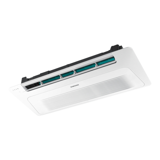
- Page 1 Air conditioner Installation manual NN1PKC Thank you for purchasing this Samsung air conditioner. Before operating this unit, please read this manual carefully and retain it for future reference.
-
Page 2: Table Of Contents
Contents Safety Information Installation Procedure Step 1 Checking and preparing accessories Step 2 Choosing the installation location Step 3 Optional: Insulating the body of the indoor unit Step 4 Installing the indoor unit Step 5 Purging inert gas from the indoor unit Step 6 Cutting and flaring the pipes Step 7 Connecting the assembly pipes to the refrigerant pipes Step 8 Performing the gas leak test... -
Page 3: Safety Information
Safety Information WARNING CAUTION WARNING General information WARNING Installing the unit WARNING IMPORTANT: When installing the unit, always remember to connect first the refrigerant tubes, then the electrical lines. English... - Page 4 Safety Information – – Step 13 Optional: Extending the power cable CAUTION Make sure that you earth the cables. Power supply line, fuse or circuit Install the circuit breaker. breaker WARNING Make sure that the condensed water dripping from the drain hose runs out properly and safely.
-
Page 5: Installation Procedure
Installation Procedure Step 1 Checking and preparing Step 2 Choosing the installation accessories location Installation location requirements Pattern sheet A (1) Insulation pipe (2) Pattern sheet B (1) Flexible hose (1) Insulation drain (1) Do not install the air conditioner in following Rubber Installation manual (1) places. - Page 6 Installation Procedure Indoor unit dimensions Slim 1way cassette (Medium) 1150 (Ceiling opening dimension) 1036 (Space of suspension bolts) Ceiling 1198 Model Liquid pipe connection Gas pipe connection Drain hose connection English...
- Page 7 Slim 1way cassette (Large) 1380 (Ceiling opening dimension) 1260 (Space of suspension bolts) 1200 Ceiling 1410 Model Liquid pipe connection Gas pipe connection Drain hose connection English...
-
Page 8: Step 3 Optional: Insulating The Body Of The Indoor Unit
Installation Procedure Spacing requirements Step 3 Optional: Insulating the body of the indoor unit C: 1500 mm or more CAUTION AC052NN1PKC Indoor unit AC036NN1PKC AC071NN1PKC English... -
Page 9: Step 4 Installing The Indoor Unit
Step 4 Installing the indoor unit CAUTION CAUTION NOTE Concrete Hole in anchor Insert Hole in plug Suspension bolt (M8) - field supply Ceiling support Level English... -
Page 10: Step 5 Purging Inert Gas From The Indoor Unit
Installation Procedure Step 6 Cutting and flaring the pipes Pipe cutter Ceiling Ceiling 90° 10 mm 10 mm Gauge of dimensions <Side view> Pipe Oblique Rough Burr Step 5 Purging inert gas from the indoor unit R 0.4 to 0.8 mm Unscrew the pinch pipe at the end of each refrigerant pipe. -
Page 11: Step 7 Connecting The Assembly Pipes To The Refrigerant Pipes
Outer Diameter (mm) Damaged Cracked Uneven Correct Inclined Thickness Surface NOTE Step 6 Cutting Step 7 Connecting the assembly and flaring the pipes pipes to the refrigerant pipes There are two refrigerant pipes of different diameters : CAUTION Spanner Torque wrench Flare nut Union... -
Page 12: Step 8 Performing The Gas Leak Test
Installation Procedure Step 8 Performing the gas leak test CAUTION CAUTION Insulator Liquid side Gas side Step 9 Insulating the refrigerant pipes Hanger Additional insulation No gap Refrigerant pipe insulation a x 3 NOTE Insulation cover pipe Insulation pipe Indoor unit Be sure to overlap the insulation. -
Page 13: Step 10 Installing The Drain Hose And Drain Pipe
Step 10 Installing the drain hose and Insulation type (heating/cooling) drain pipe Standard High humidity Pipe Pipe size Remarks (Less than 30°C, (Over 30°C, 85%) 85%) EPDM, NBR <Geological condition> Drain socket Metal clamp Drain hose <Operation purpose condition> Drain pipe <Building construction condition>... - Page 14 Installation Procedure CAUTION Support pieces Air ventilation 1 to 1.5 m Ceiling Ceiling Slope of the horizontal drain pipe: 1/100 or more 300 mm Be horizontal or less 20 mm or more Drain hose Band joint 1/100 or more Indoor unit Ceiling Flexible hose Under gradient...
-
Page 15: Step 11 Performing The Drainage Test
NOTE 1000 to 1500 mm Full thread bolt hanger Individual Main air vent air vent (must be installed) CAUTION 200 mm or more 300 to 550 mm Main drain pipe Centralized horizontal drain pipe (more than 1/100 slope) – – Step 11 Performing the drainage test CAUTION Water leakage... -
Page 16: Step 12 Connecting The Power And Communication Cables
Installation Procedure Step 12 Connecting the power and CAUTION communication cables CAUTION Indoor Unit 1(L) 2(N) Outdoor Unit 1(L) 2(N) Cable Cable clamp Indoor Power Main power cable Communication cable English... -
Page 17: Step 13 Optional: Extending The Power Cable
Step 13 Optional: Extending the Indoor power supply power cable Power supply Max/Min(V) Indoor power cable Communication cable Tools Spec Shape (unit: mm) Communication: M3.5 screw AC power: M4 screw 12.6 CAUTION Power cable (Unit: mm) Pre-installed tube for the power cable CAUTION (Unit: mm) English... - Page 18 Installation Procedure Contraction tube Method 1 Method 2 Method 1 Method 2 Insulation tape Connection sleeve Connection sleeve CAUTION Compression dimension WARNING Method 1 Method 2 – Compress it 4 times. Compress it 4 times. 5 mm 5 mm Method 1 Method 2 Insulation tape Insulation tape...
-
Page 19: Step 14 Setting The Indoor Unit Addresses And The Installation Options
Step 14 Setting the indoor unit addresses and the installation options CAUTION Common steps for setting the addresses and options AR-EH03E remote controls Entering the Setting the mode for setting option values the options SEG1 SEG2 SEG3 SEG4 SEG5 SEG6 SEG7 SEG8 SEG9... - Page 20 Installation Procedure Steps Remote control display Cool English...
- Page 21 Steps Remote control display Heat Auto English...
- Page 22 Installation Procedure Steps Remote control display Cool English...
- Page 23 Steps Remote control display Heat [SEG2, SEG3] [SEG4, SEG5] [SEG6, SEG8] [SEG9, SEG10] 0 0 [SEG11, SEG12] [SEG14, SEG15] [SEG16, SEG17] 7 7 [SEG18, SEG20] 0 0 [SEG21, SEG22] [SEG23, SEG24] 4 4 English...
- Page 24 Installation Procedure Setting the indoor unit addresses Option No. for an indoor unit address: 0AXXXX-1XXXXX-2XXXXX-3XXXXX Indoor Unit Common steps for setting the addresses and options Option SEG1 SEG2 SEG3 SEG4 SEG5 SEG6 Option SEG7 SEG8 SEG9 SEG10 SEG11 SEG12 English...
- Page 25 CAUTION Setting the installation options in a batch Option No. for an indoor unit address: 02XXXX-1XXXXX-2XXXXX-3XXXXX Indoor Unit Common steps for setting the addresses and options Option SEG1 SEG2 SEG3 SEG4 SEG5 SEG6 English...
- Page 26 Installation Procedure Option SEG7 SEG8 SEG9 SEG10 SEG11 SEG12 Option SEG13 SEG14 SEG15 SEG16 SEG17 SEG18 Option SEG19 SEG20 SEG21 SEG22 SEG23 SEG24 English...
- Page 27 Changing the addresses and options individually Common steps for setting the addresses and options Option SEG1 SEG2 SEG3 SEG4 SEG5 SEG6 Option SEG1 SEG2 SEG3 SEG4 SEG5 SEG6 English...
-
Page 28: Appendix
Troubleshooting Troubleshooting LED lamp display Operation Defrost Filter Timer Abnormal conditions reset Remarks Blue Yellow English... - Page 29 Memo English...
- Page 30 Memo English...
- Page 31 English...
- Page 32 DB68-08011A-00...