
Related Manuals for EnGenius ENS500EXT-AC


Summary of Contents for EnGenius ENS500EXT-AC
- Page 1 Business Solutions User Manual ENS500-AC/ENS500EXT-AC/ ENS610EXT/ENS620EXT version 1.1 11AC Wave2 Outdoor Access Point / CPE...
- Page 2 IMPORTANT To install this Access Point please refer to the Quick Installation Guide included in the product packaging.
-
Page 3: Table Of Contents
Table of Contents Chapter 1 Product Overview..........4 Wireless Security................51 Introduction..................5 Wireless MAC Filtering............... 54 Wireless Advanced..............55 Technical Specifications.............. 8 Fast Roaming.................. 56 Physical Interface................16 WDS Link Settings............... 57 Chapter 2 Before You Begin..........19 Guest Network Settings............58 Computer Settings............... 20 Chapter 8 Management ............ -
Page 4: Chapter 1 Product Overview
Chapter 1 Product Overview... -
Page 5: Introduction
Introduction Introduction Key Features - ENS620EXT • Up to 26 dBm transmit power enabling long range connectivity • Supports IEEE802.11ac wave2/ac/a/b/g/n wireless standards with up to 400 Mbps data rate on 2.4GHz band and 867Mbps on 5GHz band • Support Wave 2 MU-MIMO function on 5GHz radio. • Support Tx Beamforming to enlarge the transmitting distance. • Perform 256-QAM to enhance air performance up to 400Mbps under the 2.4GHz radio • Two detachable 5 dBi 2.4 GHz Omni-directional antennas • Two detachable 5 dBi 5 GHz Omni-directional antennas • Proprietary 24V Input design with Gigabits port supports. • Flexible application by the built-in 2nd LAN port. • More customized items on Band Steering for intellgent Manage- ment. • Traffic Shaping to control bandwidth per SSID/user • Secured Guest Network option available Points that do not have the range and reach to connect to The AP is 802.11 ac wave2/a/b/g/n Outdoor Access Point a growing number of wireless users. With Wave2 features, with speeds up to 400 Mbps on 2.4GHz and 867Mbps... - Page 6 Features and specifications subject to change without notice. Trademarks and registered trademarks are the property of their respective owners. For United States of America: Copyright © 2017 EnGenius Technologies, Inc. All rights reserved.
- Page 7 • Pole Mount Ring x 1 • Web-Browsing A pplication ( i.e.: E dge, I nternet E xplorer, F irefox, S afari, o r • Wall Mount Screw Set another similar browser application) • Quick Installation Guide *(all items must be in package to issue a refund): Package Contents The ENS500EXT-AC package contains the following items:* The ENS620EXT package contains the following items:* • Access Point • Access Point • 2 detachable 5 dBi 5 GHz Omni-directional Antennas • 2 detachable 5 dBi 2.4 GHz Omni-directional Antennas • PoE Adapter(EPA2406GP) • 2 detachable 5 dBi 5 GHz Omni-directional Antennas...
-
Page 8: Technical Specifications
Technical Specifications ENS620EXT WDS Bridge WDS Station Standard: Management IEEE802.11 ac wave2/ac/a/n on 5 GHz Auto Channel Selection IEEE802.11 b/g/n on 2.4 GHz Multiple SSID: 16 SSIDs, 8 SSIDs per Radio Antenna BSSID 2 x detachable 5 dBi 2.4 GHz Omni-directional Antennas SNMP V1/V2c/V3 2 x detachable 5 dBi 5 GHz Omni-directional Antennas MIB I/II, Private MIB VLAN Tag/VLAN Pass-through Physical Interface Clients Statistics 2 x 10/100/1000 Gigabit Ethernet Ports with PoE support Save Configuration as User Default LAN1 Port: Proprietary 24V Input Fast Roaming LAN2 Port: Data Transmission E-Mail Alert LED Indicator RADIUS Accounting Power Guest Network LAN 1... - Page 9 Hides SSID in beacons MAC address filtering, up to 32 MACs per SSID Wireless STA (Client) connection list Https Support SSH Support QoS (Quality of Service) Complaint with IEEE 802.11e standard Physical/Environment Conditions Operating: Temperature: -20 °C to 60 °C (-4 °F to 140 °F) Humidity (non-condensing): 90% or less Storage: Temperature: -30 °C to 80 °C (-22 °F to 176 °F ) Humidity (non-condensing): 90% or less...
- Page 10 ENS610EXT WDS Bridge WDS Station Standard: Management IEEE802.11 ac wave2/ac/a/n on 5 GHz Auto Channel Selection IEEE802.11 b/g/n on 2.4 GHz Multiple SSID: 16 SSIDs, 8 SSIDs per Radio Antenna BSSID 2 x detachable 5 dBi 2.4 GHz Omni-directional Antennas SNMP V1/V2c/V3 2 x detachable 5 dBi 5 GHz Omni-directional Antennas MIB I/II, Private MIB VLAN Tag/VLAN Pass-through Physical Interface Clients Statistics 2 x 10/100/1000 Gigabit Ethernet Ports with PoE support Save Configuration as User Default LAN1 Port: Proprietary 24V Input Fast Roaming LAN2 Port: Data Transmission E-Mail Alert LED Indicator RADIUS Accounting Power Guest Network LAN 1 Traffic Shaping per SSID/user LAN 2...
- Page 11 Hides SSID in beacons MAC address filtering, up to 32 MACs per SSID Wireless STA (Client) connection list Https Support SSH Support QoS (Quality of Service) Complaint with IEEE 802.11e standard Physical/Environment Conditions Operating: Temperature: -20 °C to 60 °C (-4 °F to 140 °F) Humidity (non-condensing): 90% or less Storage: Temperature: -30 °C to 80 °C (-22 °F to 176 °F ) Humidity (non-condensing): 90% or less...
- Page 12 ENS500-AC WDS AP WDS Bridge Standard: WDS Station IEEE802.11 ac wave2/ac/a/n on 5 GHz Management Antenna Auto Channel Selection Internal 14dBi high gain directional antenna Multiple SSID: 8 SSIDs BSSID Physical Interface SNMP V1/V2c/V3 2 x 10/100/1000 Gigabit Ethernet Ports with PoE support MIB I/II, Private MIB LAN1 Port: Proprietary 24V Input VLAN Tag/VLAN Pass-through LAN2 Port: Data Transmission Clients Statistics LED Indicator Save Configuration as User Default Power Traffic Shaping per SSID/user LAN 1 E-Mail Alert LAN 2...
- Page 13 Hides SSID in beacons MAC address filtering, up to 32 MACs per SSID Wireless STA (Client) connection list Https Support SSH Support QoS (Quality of Service) Complaint with IEEE 802.11e standard Physical/Environment Conditions Operating: Temperature: -20 °C to 60 °C (-4 °F to 140 °F) Humidity (non-condensing): 90% or less Storage: Temperature: -30 °C to 80 °C (-22 °F to 176 °F ) Humidity (non-condensing): 90% or less...
- Page 14 ENS500EXT-AC ENS500EXT-AC WDS AP WDS Bridge Standard: Standard: WDS Station IEEE802.11 ac wave2/ac/a/n on 5 GHz IEEE802.11 ac wave2/ac/a/n on 5 GHz Management Antenna Antenna Auto Channel Selection 2 x detachable 5 dBi 5 GHz Omni-directional Antennas 2 x detachable 5 dBi 5 GHz Omni-directional Antennas Multiple SSID: 8 SSIDs BSSID Physical Interface Physical Interface SNMP V1/V2c/V3 2 x 10/100/1000 Gigabit Ethernet Ports with PoE support 2 x 10/100/1000 Gigabit Ethernet Ports with PoE support MIB I/II, Private MIB LAN1 Port: Proprietary 24V Input LAN1 Port: Proprietary 24V Input VLAN Tag/VLAN Pass-through LAN2 Port: Data Transmission LAN2 Port: Data Transmission Clients Statistics...
- Page 15 Hides SSID in beacons MAC address filtering, up to 32 MACs per SSID Wireless STA (Client) connection list Https Support SSH Support QoS (Quality of Service) Complaint with IEEE 802.11e standard Physical/Environment Conditions Operating: Temperature: -20 °C to 60 °C (-4 °F to 140 °F) Humidity (non-condensing): 90% or less Storage: Temperature: -30 °C to 80 °C (-22 °F to 176 °F ) Humidity (non-condensing): 90% or less...
-
Page 16: Physical Interface
Physical Interface (ENS620EXT) Dimensions and Weights Length: 191.6 mm (7.54”) Width: 114.3 (4.49”) Depth: 47.7mm (1.88”) 1 2.4 GHz Antennas: Detachable 5 dBi 2.4 GHz Omni-directional 2 5 GHz Antennas Detachable 5 dBi 5 GHz Omni-directional 3 LAN Port 1 (Proprietary24V PoE): Ethernet port for RJ-45 cable. 4 LAN Port 2 : Ethernet port for RJ-45 cable. 5 LED Indicators: LED lights for Power, LAN Port 1, LAN Port 2, 2.4 GHz Connection and 5 GHz Connection. - Page 17 Physical Interface (ENS610EXT) Dimensions and Weights Length: 191.6 mm (7.54”) Width: 114.3 (4.49”) Depth: 47.7mm (1.88”) 1 2.4 GHz Antennas: Detachable 5 dBi 2.4 GHz Omni-directional 2 5 GHz Antennas Detachable 5 dBi 5 GHz Omni-directional 3 LAN Port 1 (Proprietary24V PoE): Ethernet port for RJ-45 cable. 4 LAN Port 2 : Ethernet port for RJ-45 cable. 5 LED Indicators: LED lights for Power, LAN Port 1, LAN Port 2, 2.4 GHz Connection and 5 GHz Connection.
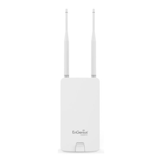
- Page 18 Physical Interface - ENS500-AC/ENS500EXT-AC Dimensions and Weights Length: 186 mm (7.32”) Width: 100 (3.94”) Depth: 29mm (1.14”) 1 5 GHz Antennas Detachable 5 dBi 5 GHz Omni-directional Antennas (ENS500EXT-AC Only) 2 LAN Port 1 (Proprietary24V PoE): Ethernet port for RJ-45 cable. 3 LAN Port 2 : Ethernet port for RJ-45 cable. 4 LED Indicators: LED lights for Power, LAN Port 1, LAN Port 2, 2.4 GHz Connection and 5 GHz Connection.
-
Page 19: Chapter 2 Before You Begin
Chapter 2 Before You Begin... -
Page 20: Computer Settings
Computer Settings Windows XP/Windows 7/Windows 8/Windows 1b. Move your mouse to the lower right hot corner to display the Charms Bar and select the Control Panel in Windows 8 OS. In order to use the Access Point, you must first configure the TCP/IPv4 connection of your Windows OS computer system. 1a. Click the Start button and open the Control Panel Windows 8 1c. - Page 21 4. Select Internet Protocol Version 4 (TCP/IPv4) and then 2a. In Windows XP, click Network Connections. select Properties. 2b. In Windows 7/Windows 8/Windows 10, click View Network Status and Tasks in the Network and Internet section, then select Change adapter settings. 3. Right click on Local Area Connection and select Properties. 5.
- Page 22 Note: Ensure that the IP address and Subnet mask are on the same subnet as the device. For example: ENH220EXT IP address: 192.168.1.1 PC I P a ddress: 1 92.168.1.2 – 1 92.168.1.255 PC Subnet mask: 255.255.255.0...
- Page 23 Apple Mac OS X 4. In Configure IPv4, select Manually. 1. Go to System Preferences (Which can be opened in the 5. Enter an IP address that is different from the Access Applications folder or selecting it in the Apple Menu). Point and Subnet mask then press OK. 2. Select Network in the Internet & Network section. Note: Ensure that the IP address and Subnet mask are on the same subnet as the device.
-
Page 24: Hardware Installation
E. Place the pane removed from step A back into the device. F. Screw on the provided antennas to the top of this device. Note: The Access Point NOLY supports the included (Applied on the ENS500EXT-AC / ENS610EXT/ENS620EXT) proprietary 24V PoE adapter. This diagram depicts the hardware configuration. -
Page 25: Mounting The Ap
Mounting the AP Using the provided hardware, the AP can be attached to a wall or a pole. 1. Wall Mounting Kit 2. Pole Mounting Strap (Anchors: Φ5.5*18 mm & Bolts: Φ8*25mm) (Φ63.5*12.7 mm) Bolts Anchors... - Page 26 To attach the AP to a wall using wall mounting kit. 1. Determine where the Access Point to be placed and 3. Screw the included screws into the anchors. mark locations on a surface for the two mounting holes. 4. Place this Access Point against wall with the mounting Use an appropriate drill bit to drill two 8.1mm diagram heads.
- Page 27 To attach the AP to a pole using the provided pole mounting kit: 1. Thread the open end of the pole strap through the two 2. Lock and tighten pole strap to secure pole mount bracket to the pole. tabs on the Pole Mount Bracket.
-
Page 28: Install Ground Cable
Install Ground cable (ENS620EXT Only) No outdoor APs are built to withstand a direct lightning strike. To prevent a directly ligtning stirke into outdoor APs, they should be properly grounded to a viable path for lightning surge to deliver to ground so that is does not go into the building network. This AP have a ground lug on the left side of this AP which is applied to attach a proper ground to. *Attention: You must always install an external grounding wire ensure that you have completed grounding before you connect power to the unit. -
Page 29: Chapter 3 Configuring Your Access Point
Chapter 3 Configuring Your Access Point... -
Page 30: Default Settings./Web Configuration
Configuring Your Access Point This section will show you how to configure the device 2. The default username and password are admin. using the web-based configuration interface. Once you have entered the correct username and password, click the Login button to open the web-base Default Settings configuration page. Please use your Ethernet port or wireless network adapter to connect the Access Point. -
Page 31: Chapter 4 Building A Wireless Network
Chapter 4 Building a Wireless Network... -
Page 32: Access Point Mode
Before starting to configure this Access Point, you may realize the used scenario under varied operating modes.The AP has the ability to operate in various modes. This chapter describes purpose of different operating modes and lists down the operating modes for outdoor Access Points or Client Premise Equipments (CPE). Access Point Mode In Access Point Mode, AP behaves likes a central connection for stations or clients that support IEEE 802.11ac/a/b/g/n networks. The stations and clients must be configured to use the same SSID (Service Set Identifier) and security password to associate with the AP. The AP supports up to eight SSIDs per band at the same time for secure access. Access Point Client Client... -
Page 33: Client Bridge Mode
Client Bridge Mode The Access Point essentially acts as a wireless adapter that connects to an access point to allow a system of wireless access to the network in the Client Bridge mode. Since the computers are on the same subnet, the Access Point can broadcast to reach all end-devices. If you use the client bridge mode in this Access Point, you can use the AP Detection feature to scan for Access Points within range. When you find an Access Point, configure this Access Point to use the same SSID and Security Password as the Access Point to associate with it. - Page 34 The AP can be used as a centralized Outdoor Access Point with which other EnGenius Wireless 802.11b/g/n 2.4 or ac/a/n 5 GHz Outdoor Client Bridges can associate; leveraging the long-range capability of their internal high-gain directional antennas, resulting in a very cost-effective solution to expand a company network over a multiple building campus. ENH202 ENH202 Client Bridge Client Bridge Client Access Point Client 2.4 GHz 2.4 GHz Client Client Client 5 GHz 5 GHz ENH500...
-
Page 35: Wds Ap Mode
WDS AP Mode The AP also supports WDS AP mode. This operating mode allows wireless stations to connect with Access Point via using WDS technology. In this mode, configure the MAC addresses or SSIDs in both Access Points to enlarge the wireless area by enabling WDS Link settings. WDS AP mode supports up to four (4) AP MAC addresses and four (4) SSIDs at the same time. WDS AP WDS AP 5 GHz 5 GHz Client Client Computer Computer 2.4 GHz 2.4 GHz Client Client... -
Page 36: Wds Bridge Mode
WDS Bridge Mode In WDS Bridge Mode, the Accesss Point can wirelessly connect different LANs by configuring the MAC address and security settings of each Access Points. Use this operating mode when two wired LANs located a small distance apart want to communicate with each other. The best solution is to use the Access Point to wirelessly connect two wired LANs, as shown in the following diagram. WDS Bridge Mode can establish up to four (4) to eight (8) WDS links, creating a star-like network. Note: WDS Bridge Mode does not act as an Access Point. Access Points linked by WDS are using the same frequency channel. More Access Points connected together may lower throughput. This configuration can be susceptible to generate endless network loops in your network, so it is recommended to enable the Spanning Tree function to prevent this from happening. -
Page 37: Wds Station Mode
WDS Station Mode WDS station (WDS STA) mode expands the WDS by receiving a wireless signal/service and sharing it through the Ethernet port. With WDS STA mode, Access Point WDS AP on both 5 GHz or 2.4 GHz Access Point Access Point WDS Station WDS Station... -
Page 38: Chapter 5 Status
Chapter 5 Status... -
Page 39: Overview
Overview Save Changes Note: VLAN ID is only applicable in Access Point, WDS AP or WDS BR mode. This page lets you save and apply the settings shown under Unsaved changes list, or Revert the unsaved changes and revert to the previous settings that were in effect. The Memory Information section shows usage of •... - Page 40 • The LAN Information section shows the Local Area Network settings such as the LAN IP Address, Subnet mask, Primary DNS Address, Secondary DNS Address, status of DHCP client, and status of Spanning Tree protocol (STP). The Wireless LAN Information 2.4 GHz/5 GHz section shows wireless information such as Operation Mode, Frequency, and Channel. Since this Access Point supports multiple-SSIDs, information about each SSID, the ESSID, and security settings, are displayed...
-
Page 41: Connection
Connections Realtime 2.4 GHz/5 GHz Connection List Realtime Click the connection link under the Overview menu displays The Realtime section contains the following options: the connection list of clients associated to the AP’s 2.4 CPU Loading: 3 minutes CPU loading percentage GHz/5 GHz, along with the MAC addresses and signal information, it displays current loading, average loading strength for each client. - Page 42 Traffic Loading: 2.4GHz and 5GHz and Ethernet port inbound and outbound traffic by current, average and peak time. Realtime Connection (Pkts): Overview on current active network connections. It displays UDP and TCP packets information and other connection status. UDP connections curve is in blue; TCP connection curve is in green; others curve is in red. Below of chart shows connections source and destination.
-
Page 43: Chapter 6 Network
Chapter 6 Network... -
Page 44: Basic Ipv4/Ipv6 Settings
Basic IPv4/IPv6 Settings Primary/Secondary DNS: The primary/secondary DNS address for this device. This page allows you to modify the device’s IP settings. Save: Click Save to confirm the changes. Spanning Tree Protocol (STP) Settings This page allows you to modify the Spanning Tree settings. Enabling the Spanning Tree protocol will prevent network loops in your LAN network. - Page 45 bridge in the spanning tree does not send a hello packet for a long period of time, it is assumed to be inactive. Forward Delay: Specifies Bridge Forward Delay in seconds. Forwarding delay time is the time spent in each of the Listening and Learning states before the Forwarding state is entered. This delay is provided so that when a new bridge comes onto a busy network, it analyzes data traffic before participating in the network.
-
Page 46: Chapter 7 2.4 Ghz/5 Ghz Wireless
Chapter 7 2.4 GHz & 5 GHz Wireless... -
Page 47: Wireless Settings
2.4GHz to operate at their slower rates. Before implementing this feature, we suggest you to assure the both 2.4GHz and 5GHz SSID, as welll as security settings *Band Balance: When band steering is configured to must be the same. EnGenius Band Steering supports Band Balance mode, the AP will steer dual band capable following advanced settings, client devices to 5GHz when the RSSI value of these client devices on 5GHz radio is more than set one. -
Page 48: 2.4 Ghz/5 Ghz Wireless Network
Access Point on base stations and Access Points and is Client Bridge on Client Premise Equipements (CPE). Meanwhile, EnGenius outdoor devices also support WDS modes for peer to peer or peer to multi-peer connections. Wireless Mode: Scrow down this list to select wireless broadcasting standard on 2.4GHz and 5GHz frequency... - Page 49 *Default configuration: Default setting of channel assocaited client devices will be restricted at this number. selection is “All” to perform auto channel on the exist Aggregation: Integrate multiple data packets into one channel list. packet to deliver to client devices. This option reduces the number of packets, but also increases packet sizes.
-
Page 50: 2.4 Ghz/5 Ghz Ssid Profile
2.4 GHz/5 GHz SSID Profile Enable: Click this check box to enable this SSID interface. The default SSIDs are enable on the both first 2.4GHz and 5GHz SSID. SSID: Specifies the SSID for the current profile. Hidden SSID: Check this option to hide the SSID from clients. If checked, the SSID will not appear in the site survey. Client Isolation: Click the appropriate radio button to enable this function for allowing or preventing communication between client devices. VID: Specifies the VLAN tag for each profile. If your netowrk includes VLANs, you can specify a VLAN ID for packets pass through the Access Point with a tag. -
Page 51: Wireless Security
Wireless Security Input Type: ASCII: Regular Text (recommended) The Wireless Security section lets you configure the AP’s Hexadecimal Numbers (For advanced users) security modes Key Length: Select the desired option and ensure that wireless clients use the same setting. Your choices are 64, 128, and 152-bit password lengths. Default Key: Select the Key you wish to be the default. Transmitted data is ALWAYS encrypted using the Default Key; the other Keys are for decryption only. You must enter a Key Value for the Default Key. - Page 52 * Setting of WPA-PSK, WPA2-PSK and WPA-PSK Mixed (Pre-Shared Key): Encryption: You may select AES, TKIP or Both (TKIP+AES) to be the encryption type you would like. Please ensure that your wireless clients use the same settings. Passphrase: Wireless clients must use the same Key to associate the device. If using ASCII format, the Key must * Setting of WPA-Enterprise & WPA2-Enterprise (Pre- be from 8 to 63 characters in length. If using HEX format, Shared Key): the Key must be 64 HEX characters in length.
- Page 53 Radius Secret: Enter the secret required to connect to the Radius server. Radius Accounting: Enable or disable accounting feature. Radius Accounting Server: Enter the IP address of the Radius accounting server. Radius Accounting Port Enter the port number used for connections to the Radius accounting server.
-
Page 54: Wireless Mac Filtering
Wireless MAC Filtering Add: Click Add to add the MAC address to the MAC address table. Wireless MAC Filtering is used to allow or deny network Delete: Delete the selected entries. access to wireless clients (computers, tablet PCs, NAS, smartphones, etc.) according to their MAC addresses. You Save: Click Save to apply the changes. -
Page 55: Wireless Advanced
Wireless Advanced Save: Click Save to confirm the changes. Wireless Traffic Shaping Traffic shaping regulates the flow of packets leaving an interface to deliver improved Quality of Service. Enable Traffic Shaping: Default is disable. You may check this option to enable Wireless Traffic Shaping per SSID. Download Limit: Specifies the wireless transmission speed used for downloading. Upload Limit: Specifies the wireless transmission speed used for uploading. Per User: Check this option to enable wireless traffic shaping per user function. -
Page 56: Fast Roaming
Fast Roaming Enable the function to serve mobile client devices that roam from Access Point to Access Point. Some applications running on Client devices require fast re-association when they roam to a different Access Point Enable Fast Roaming: Enable or disable fast roaming Please enter the settings of the SSID and initialize the Security feature. -
Page 57: Wds Link Settings
WDS Link Settings 2.4 GHz/5 GHz WDS Link Settings Using the WDS (Wireless Distribution System) feature will allow a network administrator or installer to connect to Access Points wirelessly. Doing so will extend the wired infrastructure to locations where cabling is not possible or inefficient to implement. Note: Compatibility between different brands and models of Access Points is not guaranteed. -
Page 58: Guest Network Settings
Guest Network Settings the addresses by the DHCP server. Adding a guest network allows visitors to use the Internet without giving out your office or company wireless Ending IP Address: The last IP Address in the range of security key. You can add a guest network to each addresses assigned by the DHCP server. -
Page 59: Chapter 8 Management
Chapter 8 Management... -
Page 60: Management Vlan Settings
Management VLAN Settings This page allows you to assign a VLAN tag to packets sent DHCP server supports the reconfigured VLAN ID and over the network. A VLAN is a group of computers on a then reconnect to this AP using the new IP address. network whose software has been configured so that they behave as if they were on a separate Local Area Network (LAN). Computers on VLAN do not have to be physically... -
Page 61: Advanced Settings
Advanced Settings SNMP Settings SNMP Enable/Disable: Enables or disables the SNMP feature. This page allows you to assign the Contact Details, Location, Contact: Specifies the contact details of the device. Community Name, and Trap Settings for a Simple Network Location: Specifies the location of the device. Management Protocol (SNMP). SNMP is a networking management protocol used to monitor network attached Community Name (Read Only): Specifies the password devices. SNMP allows messages (called protocol data units) for the SNMP community for read only access. to be sent to various parts of the network. Upon receiving Community Name (Read/Write): Specifies the password these messages, SNMP compatible devices (called agents) - Page 62 Engine ID: Specifies the engine ID for SNMPv3. Email Alert Apply Save: Click Apply Save to apply the changes. You can use the Email Alert feature to send messages to the configured email address when particular system CLI Settings events occur. Note: Do NOT use your personal email address as it can unnecessarily expose your personal email login credentials.
- Page 63 Username: Enter the username for the email account that will be used to send emails. Password: Enter the password for the email account that will be used to send emails. SMTP Server: Enter the IP address or hostname of the outgoing SMTP server.
-
Page 64: Time Zone
Time Zone Time Setting Manually Set Date and Time: Manually specify the This page allows you to set the internal clock of the AP. date and time. Synchorize with PC: Click this button to synchorize Date and time of this AP with the PC. Automatically Get Date and Time: Select Automatically Get Date and Time and check whether you wish to enter the IP address of an NTP server or use the default NTP server to have the internal clock... -
Page 65: Auto Reboot Settings
Auto Reboot Settings You can specify how often you wish to reboot the AP. Auto Reboot Setting: Enables or disables the Auto Reboot function. Timer: Select the day and enter the time you would like to reboot automatically. Save: Click Save to apply the changes. -
Page 66: Wi-Fi Scheduler
Wi-Fi Scheduler SSID Selection: Select a SSID from the drop-down list. Schedule Templates: Select a schedule template from the The Wi-Fi Scheduler can be created for use in enforcing drop-down list. rules. For example, if you wish to restrict web access to Mon-Fri from 3pm to 8pm, you could create a schedule Day(s): Place a checkmark in the boxes for the desired days selecting Mon, Tue, Wed, Thu and Fri while entering a Start... -
Page 67: Tools
Tools Ping Test Parameters Start Ping: Click Start Ping to begin pinging the target device (via IP). This page allows you to analyze the connection quality Traceroute Target: Enter the IP address or domain name of the AP and trace the routing table to a target in the you wish to trace. - Page 68 Speed Test Parameters / LED Control This page allows you to implement speed test to realize LED Control the throughput of a target DUT. Control LED on/off for Power, LAN interface, or 2.4 GHz/5 GHz WLAN interface. Target IP / Domain Name: Enter an IP address or domain name you wish to impelement a speed test for realizing Power: Enables or disables the Power LED indicator.
- Page 69 Device Discovery This page allows you to discover devices from network for Operation Mode, IP Address, System MAC Address and Firmware version.
-
Page 70: Account/Firmware
Firmware Account This page allows you to change the AP username and Firmware Upgrade password. By default, the username is: admin and the This page allows you to upgrade the firmware of the password is: admin. The password can contain from 0 to 12 alphanumeric characters and is case sensitive. -
Page 71: Backup/Restore
Backup/Restore Backup Setting: Click Export to save the current This page allows you to save the current device configured settings. configurations. When you save your configurations, you also can reload the saved configurations into the Restore New Setting: To restore settings that have device through the Restore Saved Settings from a file been previously backed up, click Browse, select the section. If extreme problems occur, or if you have set... - Page 72 User Setting Back Up Setting as Default: Click Backup to backup the user settings you would like to the device’s memory The function allows you to backup the current device for the default settings. configurations into the AP as the default value. If Restore to User Default: Click Restore to restore user extreme problems occur, or if you have set the AP settings to the factory standard settings.
-
Page 73: Log
System Log Log type You may choose one of log types to display logs in the following window. The default log types is All. The AP automatically logs (records) events of possible interest in its internal memory. To view the logged information, click the Log link under the System Manager menu. -
Page 74: Logout/Reset
Logout Logout: Click Logout in Management menu to logout. Once you click reset button, you will see the options for reboot or restore this AP. Please confirm again to logout the system or not. Reboot the device: Click it to reboot this device. Restore to Factory Default: Click it to reset this device to factory default setting. Restore to User Default: Click it to reset this device to user default settings. For realizing the setting method, Reset you may refer page 65 and page 66. In some circumstances, it may be required to force the device to reboot. -
Page 75: Appendix
Appendix... -
Page 76: Fcc Interference Statement
25 cm between the radiator & your body. ENS500-AC/ENS500EXT-AC: This equipment complies with FCC radiation exposure limits set forth for an uncontrolled environment. This equipment should be installed and operated with minimum distance 25 cm between the radiator & your body. -
Page 77: Ce Interference Statement
Appendix B - CE Interference Statement Europe – EU Declaration of Conformity This device complies with the essential requirements of the R&TTE Directive 1999/5/EC. The following test methods have been applied in order to prove presumption of conformity with the essential requirements of the R&TTE Directive 1999/5/EC: • EN60950-1 Safety of Information Technology Equipment • EN50385 Generic standard to demonstrate the compliance of electronic and electrical apparatus with the basic restrictions related to human exposure to electromagnetic fields (0 Hz - 300 GHz) • EN 300 328 Electromagnetic compatibility and Radio spectrum Matters (ERM);... - Page 78 This device is a 5GHz wideband transmission system (transceiver), intended for use in all EU member states and EFTA countries, except in France and Italy where restrictive use applies. In Italy the end-user should apply for a license at the national spectrum authorities in order to obtain authorization to use the device for setting up outdoor radio links and/or for supplying public access to telecommunications and/or network services.
- Page 79 Français [French] Par la présente [nom du fabricant] déclare que l’appareil [type d’appareil] est conforme aux exigences essentielles et aux autres dispositions pertinentes de la directive 1999/5/CE. Italiano [Italian] Con la presente [nome del costruttore] dichiara che questo [tipo di apparecchio] è conforme ai requisiti essenziali ed alle altre disposizioni pertinenti stabilite dalla direttiva 1999/5/CE.
-
Page 80: Professional Installation Instruction
Appendix C - Professional Installation Instruction Installation Personal general user shall not attempt to install or change the setting. Installation Location The product shall be installed at a location where the radiating antenna can be kept 25cm from nearby person in normal operation condition to meet regulatory RF exposure requirement.