Advertisement
Quick Links
INSTRUCTIONS
COMPENSATORS
Optical Microscope Accessory
This instruction manual is for the Olympus Compensators. As this manual pertains only to the compensators,
also refer to the instruction manual for your polarizing microscope (BX53/BX53M-P or CX31-P) so that you
understand the operating procedures of the entire system.
To ensure the safety, obtain optimum performance and familiarize yourself fully with the use of these units,
we recommend that you study this manual thoroughly before using them.
Retain this instruction manual in an easily accessible place near the work desk for future reference.
A X 5 8 9 4
Advertisement

Related Manuals for Olympus U-CBE


Summary of Contents for Olympus U-CBE
- Page 1 COMPENSATORS Optical Microscope Accessory This instruction manual is for the Olympus Compensators. As this manual pertains only to the compensators, also refer to the instruction manual for your polarizing microscope (BX53/BX53M-P or CX31-P) so that you understand the operating procedures of the entire system.
- Page 2 IMPORTANT These units employ a UIS2/UIS (Universal Infinity System) optical design, and should be used only with a microscope, eyepieces, objectives and condenser matching the UIS/UIS2 optics. Less than optimum performance may result if inappropriate accessories are used. Getting Ready 1.
-
Page 3: Table Of Contents
CONTENTS 1 OUTLINE 2 NOMENCLATURE 3 ASSEMBLY 4 PREPARATION AND MEASUREMENT 4-1 Berek Compensator (U-CBE), .....................................7 Thick Berek Compensator (U-CTB) ................................7 4-2 Brace-Köhler Compensator (U-CBR1, U-CBR2) ......................11 4-3 Quarts Wedge (U-CWE2) ..................................14 4-4 Senarmont Compensator (U-CSE) .............................16... - Page 4 Measuring Range of Compensators Compensator Name Measuring Range λ Thick Berek (U-CTB) 0 -- 20 λ Berek (U-CBE) 0 -- 3 λ Quartz Wedge (U-CWE2) 1 -- 4 λ * Senarmont Compensator (U-CSE) 0 -- 1 λ...
-
Page 5: Berek Compensator (U-Cbe)
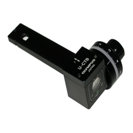
U-CBE, U-CTB NOMENCLATURE Berek Compensator (U-CBE) Thick Berek Compensator (U-CTB) Compensator Scale 1 0-60° Scale 2 (minimum reading 10°) One turn equals 10° (minimum reading 0.05°) Compensator knob * The illustration shows the U-CTB. The U-CBE’s γ axis direction is different. - Page 6 U-CBR1, U-CBR2 Brace-Köhler Compensator (U-CBR1, U-CBR2) Scale 2 Compensator One turn equals 20° (minimum reading 0.1°) Compensator knob Scale 1 40-0-40° (minimum reading 20°) * The illustration shows the U-CBR2. The U-CBR1 is the model with the same design as the U-CBR2 but only the product name is different.
- Page 7 U-CWE2, U-CSE Quartz Wedge Senarmont Compensator (U-CWE2) (U-CSE) Compensator Compensator Retardation indication...
- Page 8 ASSEMBLY } The assembly method is the same for all the compensators. The compensator is designed to be inserted in the test plate adapter (U-TAD) or polarization attachment (U-PA). With U-TAD ² 1. Loosen the clamping knob @ at the front of the revolving nosepiece and remove the dummy slider.
- Page 9 If it is required to maintain brightness and resolution, the top-lens should be left engaged although measuring accuracy will decrease. } When measuring retardation, backlash error may occur when the compensator knob is rotated (U-CBE, U-CTB, U-CBR1, U-CBR2). Accordingly, keep the rotation direction always uniform. If the knob is rotated...
- Page 10 2. Rotate the stage further by +45° and then clamp it. 3. Rotate the compensator knob and set the U-CBE or U-CTB scale to position 30°. 4. Insert the U-CBE or U-CTB into the test plate adapter (U-TAD) or polarization attachment (U-PA) as far as it will go. Fig. 2-2...
- Page 11 If the black fringe does not intersect the center of the field of view even after rotating the stage 90°, the retardation of the specimen is outside the measurable range, and measuring with the U-CBE or U-CTB is not possible. (See page 1)
- Page 12 U-CBE, U-CTB Measuring Retardation } If an interference filter (IF 546 or IF 550) is available, use it in this measurement. 1. Place an interference filter in the filter holder of the microscope frame. # If an interference filter is used, multiple black dots or fringes will be visible.
- Page 13 U-CBE, U-CTB 5. After finding the mean value θ, use the conversion table provided with the compensator to find the retardation. The formula on the next page may also be used to find the retardation. # If on interference filter is used, use the data on the e-line of the conversion table.
-
Page 14: Brace-Köhler Compensator (U-Cbr1, U-Cbr2)
U-CBR1, U-CBR2 4-2 Brace-Köhler Compensator (U-CBR1, U-CBR2) Measuring the Fiducial Point 1. Insert the U-CBR1 or U-CBR2 into the test plate adapter (U-TAD) or polarization attachment (U-PA) as far as it will go. 2. Rotate the compensator knob to obtain extinction. At this point, find the angle by totaling the readings of Scales 1 and 2. - Page 15 U-CBR1, U-CBR2 5. Rotate the compensator knob to adjust in such a manner that (Tip) γ the point to be measured on the specimen attains extinction. axis direction (vibration direction in which the speed of the light becomes slower) when the At this point, read the angle.
- Page 16 U-CBR1, U-CBR2 If the specimen does not become dark even after rotating the stage, the retardation of the specimen is outside the measurable range, and measuring with the U-CBR1 or U-CBR2 is not possible. (See page 1) 6. To find the retardation, insert the read angles into the following formula: │...
-
Page 17: Quarts Wedge (U-Cwe2)
U-CWE2 4-3 Quarts Wedge (U-CWE2) Measuring (Note) Do not use the interference filter (IF 546 or IF 550) in the following measurement. Otherwise, the measurement will not be possible. Specimen Placement 1. Position the specimen on the rotatable stage (U-SRP) and focus on the specimen. Adjusting the Rotation Position 1. - Page 18 (*), find the retardation by comparing the background color outside the measuring point and the color at the measuring point when the U-CWE2 is removed from the optical path. (*) Download the file of interference color chart from OLYMPUS webside (below mentioned URL). http://www.olympus-ims.com/microscope/bx-pol-chart...
-
Page 19: Senarmont Compensator (U-Cse)
U-CSE 4-4 Senarmont Compensator (U-CSE) Measuring } Always use interference filter (IF 546 or IF 550). If interference filter is not used, measurement will not be possible. # Due to its high detection sensitivity, use of the IF546 interference filter is recommended. Adjusting of Analyzer Angle # Perform the following adjustment with no specimen positioned on the stage. - Page 20 U-CSE Specimen Placement 1. Position the specimen on the rotatable stage (U-SRP), in such a manner that the specimen center portion coincides with the intersection of the eyepiece cross lines, and focus on the specimen. Adjusting the Fiducial Point 1. Rotate the stage and adjust so that the measured portion on the specimen becomes dark. 2.
- Page 21 MEMO...
- Page 22 MEMO...
- Page 24 Manufactured by Shinjuku Monolith, 2-3-1 Nishi-Shinjuku, Shinjuku-ku, Tokyo 163-0914, Japan Distributed by 48 Woerd Avenue Waltham, MA 02453, U.S.A. 8F Olympus Tower, 446 Bongeunsa-ro, Gangnam-gu, Seoul, 06153 Korea AX5894 07...