Siemens SIMATIC NET SCALANCE W774-1 Operating Instructions Manual
Industrial wireless lan
Hide thumbs
Also See for SIMATIC NET SCALANCE W774-1:
- Operating instructions manual (66 pages) ,
- Operating instructions manual (68 pages)
Table of Contents
Advertisement
Quick Links
SCALANCE W774-1 / W734-1
SIMATIC NET
Industrial Wireless LAN
SCALANCE W774-1 / W734-1
Operating Instructions
SCALANCE W Mainstream (MSN)
03/2022
C79000-G8976-C325-15
Introduction
Safety notices
Security
recommendations
Description of the device
Installation and removal
Connection
Maintenance and cleaning
Upkeep and maintenance
Technical data
Dimension drawings
Approvals
1
2
3
4
5
6
7
8
9
10
11
Advertisement
Table of Contents

Related Manuals for Siemens SIMATIC NET SCALANCE W774-1


Summary of Contents for Siemens SIMATIC NET SCALANCE W774-1
- Page 1 SCALANCE W774-1 / W734-1 Introduction Safety notices Security SIMATIC NET recommendations Description of the device Industrial Wireless LAN SCALANCE W774-1 / W734-1 Installation and removal Connection Operating Instructions Maintenance and cleaning Upkeep and maintenance Technical data Dimension drawings Approvals SCALANCE W Mainstream (MSN) 03/2022 C79000-G8976-C325-15...
- Page 2 Note the following: WARNING Siemens products may only be used for the applications described in the catalog and in the relevant technical documentation. If products and components from other manufacturers are used, these must be recommended or approved by Siemens. Proper transport, storage, installation, assembly, commissioning, operation and maintenance are required to ensure that the products operate safely and without any problems.
-
Page 3: Table Of Contents
Table of contents Introduction ............................. 5 Safety notices ............................9 Security recommendations ........................11 Description of the device ........................19 Structure of the type designation ....................19 Device view ............................ 20 4.2.1 SCALANCE W7x4-1 RJ45 ......................20 4.2.2 SCALANCE W774-1 M12 ......................21 Components of the product ...................... - Page 4 Table of contents Maintenance and cleaning ........................59 Upkeep and maintenance ........................61 Device configuration with PRESET-PLUG ................61 Restoring the factory settings ..................... 63 Firmware update via WBM or CLI not possible ................ 65 Technical data ............................67 SCALANCE W774/W734 RJ45 ..................... 67 SCALANCE W774 M12 ........................
-
Page 5: Introduction
Make sure that you read the explanations and instructions in the readme.htm file Documentation on the Internet You can find the current version of the document on the Internet at (https://support.industry.siemens.com/cs/de/en/ps/15859/man) Enter the name or article number of the product in the search filter. SCALANCE W774-1 / W734-1... - Page 6 (https://www.siemens.com/industrialsecurity). Siemens’ products and solutions undergo continuous development to make them more secure. Siemens strongly recommends that product updates are applied as soon as they are available and that the latest product versions are used. Use of product versions that are no longer supported, and failure to apply the latest updates may increase customer’s...
- Page 7 Firmware The firmware is signed and encrypted. This ensures that only firmware created by Siemens can be downloaded to the device. The firmware is available on the Internet pages of the Siemens Industry Online Support: (https://support.industry.siemens.com/cs/de/en/ps/15860/dl) Note on firmware/software support Check regularly for new firmware/software versions or security updates and apply them.
- Page 8 Introduction SCALANCE W774-1 / W734-1 Operating Instructions, 03/2022, C79000-G8976-C325-15...
-
Page 9: Safety Notices
Safety notices CAUTION To prevent injury and damage, read the manual before using the device. Read the safety notices Note the following safety notices. These relate to the entire working life of the device. You should also read the safety notices relating to handling in the individual sections, particularly in the sections "Installation"... - Page 10 Safety notices SCALANCE W774-1 / W734-1 Operating Instructions, 03/2022, C79000-G8976-C325-15...
-
Page 11: Security Recommendations
OpenVPN). • Separate connections correctly (WBM, SSH etc.). • Check the user documentation of other Siemens products that are used together with the device for additional security recommendations. • Using remote logging, ensure that the system protocols are forwarded to a central logging server. - Page 12 Security recommendations • Replace the default passwords for all user accounts, access modes and applications (if applicable) before you use the device. • Define rules for the assignment of passwords. • Use passwords with a high password strength. Avoid weak passwords, (e.g. password1, 123456789, abcdefgh) or recurring characters (e.g.
- Page 13 • Verify certificates based on the fingerprint on the server and client side to prevent "man in the middle" attacks. Use a second, secure transmission path for this. • Before sending the device to Siemens for repair, replace the current certificates and keys with temporary disposable certificates and keys, which can be destroyed when the device is returned.
- Page 14 Security recommendations • Ensure that the latest firmware version is installed, including all security-related patches. You can find the latest information on security patches for Siemens products at the Industrial Security (https://www.siemens.com/industrialsecurity) or ProductCERT Security Advisories (https://www.siemens.com/cert) website. For updates on Siemens product security advisories, subscribe to the RSS feed on the ProductCERT Security Advisories website or follow @ProductCert on Twitter.
- Page 15 Security recommendations • If non-secure protocols and services are required, ensure that the device is operated in a protected network area. • Check whether use of the following protocols and services is necessary: – Non-authenticated and unencrypted ports – LLDP –...
- Page 16 Security recommendations • Configurable port/service Indicates whether the port number or the service can be configured via WBM / CLI. • Authentication Specifies whether the communication partner is authenticated. If optional, the authentication can be configured as required. • Encryption Specifies whether the transfer is encrypted.
- Page 17 Security recommendations The following is a list of all available Layer 2 services through which the device can be accessed. The table includes the following columns: • Layer 2 service The Layer 2 services that the device supports. • Default status The default status of the service (open or closed).
- Page 18 Security recommendations SCALANCE W774-1 / W734-1 Operating Instructions, 03/2022, C79000-G8976-C325-15...
-
Page 19: Description Of The Device
Description of the device Structure of the type designation The type designation of the device is made up of several parts that have the following meaning: SCALANCE W774-1 / W734-1 Operating Instructions, 03/2022, C79000-G8976-C325-15... -
Page 20: Device View
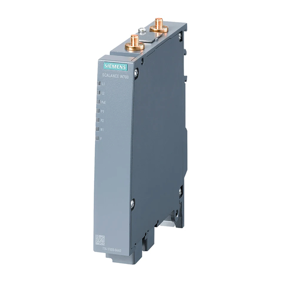
Description of the device 4.2 Device view Device view 4.2.1 SCALANCE W7x4-1 RJ45 ① Antenna connector R1A1 ② PLUG slot and Reset button ③ Antenna connector R1A2 ④ LED display ⑤ Ethernet connector P2 (PoE capability) ⑥ Ethernet connector P1 ⑦... -
Page 21: Scalance W774-1 M12
• One 4-pin terminal block for the power supply Please check that the consignment you have received is complete. If the consignment is incomplete, contact your supplier or your local Siemens office. SCALANCE W774-1 / W734-1 Operating Instructions, 03/2022, C79000-G8976-C325-15... -
Page 22: Accessories
Description of the device 4.4 Accessories Accessories Technical data subject to change. You will find further information on the range of accessories in the Industry Mall (https://mall.industry.siemens.com) Use the TIA Selection Tool (https://mall.industry.siemens.com/tst/) for configuring the device. 4.4.1 PLUG Component Description... - Page 23 Description of the device 4.4 Accessories Cables Industrial Ethernet Component Description Article number IE FC TP STANDARD Standard bus cable, TP installation cable for 6XV1840-2AH10 CABLE GP2X2 connection to FC OUTLET RJ-45, for universal use, 4-wire, shielded, CAT 5E (PROFINET type A) Sold by the meter IE FC TP ROBUST Standard bus cable, ATPE outer jacket for...
-
Page 24: Power Supply
CONNECTOR 4.4.4 Flexible connecting cables, antennas and accessories You will find an overview of the IWLAN products and their accessories in the Order overview (https://support.industry.siemens.com/cs/ww/en/view/109766333). 4.4.4.1 Flexible connecting cables Flexible connecting cable N-Connect/R-SMA Flexible connecting cable for connecting an antenna to a SCALANCE W device with R-... - Page 25 Description of the device 4.4 Accessories For railway applications, the following connecting cable are available: Length Article number 6XV1875-5TH10 6XV1875-5TH20 6XV1875-5TH50 Flexible connecting cable N-Connect/N-Connect Flexible connecting cable for connecting an antenna to a SCALANCE W device with N- Connect connectors, preassembled with two N-male connectors: Length Article number 6XV1875-5AH10...
-
Page 26: Lightning Protection
Description of the device 4.4 Accessories 4.4.4.2 Lightning protection Component Description Article number LP798-1N Lighting protector with N/N 6GK5798-2LP00-2AA6 female/female connector with gas discharge technology LP798-2N Lighting protector with N/N 6GK5798-2LP10-2AA6 female/female connector with quarter wave technology 4.4.4.3 Terminating resistor Component Description Article number... -
Page 27: Antennas
When you select an antenna, keep in mind the national approvals for your device. You will find more detailed information in Wireless approvals (https://www.siemens.com/wireless-approvals). The SCALANCE W1788-2IA uses internal omni antennas (3/4 dBi at 2.4 GHz or 5 GHz). Type... - Page 28 Description of the device 4.4 Accessories Type Properties Article number ANT795-4MD Omnidirectional antenna, 3/5 dBi, 2.4 GHz 6GK5795-4MD00-0AA3 and 5 GHz, IP65, N-Connect male for direct installation on the device, 90° connector. ANT795-4MX Omnidirectional antenna, 2/2.5 dBi, 6GK5795-4MX00-0AA0 2.4 GHz and 5 GHz, IP69K, N-Connector male ANT795-6DC Wide angle antenna, mast/wall mounting,...
-
Page 29: Led Display
Description of the device 4.5 LED display LED display Information on operating status and data transfer On the front of the housing, several LEDs provide information on the operating status of the device: Color Meaning Power supply L1 too low. Green Power supply L1 is applied. - Page 30 Description of the device 4.5 LED display Color Meaning There is no connection over the Ethernet port P1. Green There is a connection over the Ethernet port P1 (link). Flashing green Data transfer over the Ethernet interface P1. and yellow The WLAN interface 1 is deactivated.
- Page 31 Description of the device 4.5 LED display Color Meaning Flashing red The bootloader waits in this state for a new firmware file that you can download by TFTP. Interval: 500 ms on / 500 ms off Flashing red Firmware on PLUG: The device is performing a firmware update or downgrade.
-
Page 32: Reset Button
Description of the device 4.6 Reset button Reset button Position NOTICE Loss of the degree of protection When the cover is not mounted correctly, the device loses its degree of protection. The Reset button ① is on the top of the housing: SCALANCE W774-1 / W734-1 Operating Instructions, 03/2022, C79000-G8976-C325-15... - Page 33 Description of the device 4.6 Reset button Functions of the reset button The reset button has the following functions: • Restart of the device To restart the device, press the Reset button briefly. Note If you make changes to the configuration and restart immediately afterwards with the reset button, the changes may be lost.
-
Page 34: Plug
Description of the device 4.7 PLUG PLUG The PLUG is available in the following variants: • C-PLUG: The removable data storage medium only saves the configuration data of the device. • KEY-PLUG: In addition to the configuration data, the removable data storage medium contains a license with which special functions are enabled, e.g. - Page 35 Description of the device 4.7 PLUG Function The device supports the following modes of operation: • Without PLUG The device saves the configuration data in the internal memory. This mode is active when no PLUG is inserted. • With PLUG If an unwritten PLUG (factory status or deleted with Clean function) is used, the local configuration already existing on the device is automatically stored on the inserted PLUG.
- Page 36 Description of the device 4.7 PLUG SCALANCE W774-1 / W734-1 Operating Instructions, 03/2022, C79000-G8976-C325-15...
-
Page 37: Installation And Removal
Installation and removal Safety notices for installation Safety notices When installing the device, keep to the safety notices listed below. NOTICE Improper mounting Improper mounting may damage the device or impair its operation. • Before mounting the device, always ensure that there is no visible damage to the device. - Page 38 Installation and removal 5.1 Safety notices for installation WARNING If the device is installed in a cabinet, the inner temperature of the cabinet corresponds to the ambient temperature of the device. WARNING The device is intended for indoor use only. Safety notices on use in hazardous areas General safety notices relating to protection against explosion WARNING...
-
Page 39: Wall Mounting
Installation and removal 5.2 Wall mounting Safety notices when using according to FM If you use the device under FM conditions you must also keep to the following safety notices in addition to the general safety notices for protection against explosion: WARNING EXPLOSION HAZARD The equipment is intended to be installed within an enclosure/control cabinet. - Page 40 Installation and removal 5.2 Wall mounting Procedure SCALANCE W774-1 / W734-1 Operating Instructions, 03/2022, C79000-G8976-C325-15...
-
Page 41: Installing On An S7-300 Standard Rail
Installation and removal 5.3 Installing on an S7-300 standard rail 1. Prepare the drill holes for wall mounting. For the precise dimensions, refer to the drilling template. 2. Secure the device to the wall with two screws. The screws are not supplied with the device. -
Page 42: Installing On An S7-1500 Standard Rail
Installation and removal 5.4 Installing on an S7-1500 standard rail Installing on an S7-1500 standard rail Procedure Follow the steps below to fit the SCALANCE W774/W734 to an S7-1500 standard rail: 1. Place the device on the upper edge of the S7-1500 standard rail as shown in the figure. 2. -
Page 43: Installing On A Din Rail / Removing
Installation and removal 5.5 Installing on a DIN rail / removing Installing on a DIN rail / removing Procedure for installation Follow the steps below to fit the SCALANCE W774/W734 to a DIN rail: 1. Place the device on the upper edge of the DIN rail as shown in the figure. 2. - Page 44 Installation and removal 5.5 Installing on a DIN rail / removing Procedure when removing Follow the steps below to remove the SCALANCE W774/W734 from a DIN rail: 1. Turn off the power to the device. 2. Disconnect all connected cables. 3.
-
Page 45: Connection
Connection Safety when connecting up Safety notices When connecting up the device, keep to the safety notices listed below. Note Strain relief for the Ethernet cables In order to avoid mechanical stress on the Ethernet cables and resulting interruption of the contact, fasten the cables at a short distance from the connector using a cable guide or busbar. - Page 46 Connection 6.1 Safety when connecting up WARNING Danger due to lightning strikes Installing this lightning protector between an antenna and a SCALANCE W device is not adequate protection against a lightning strike. The LP798-1N lightening protector only works within the framework of a comprehensive lightning protection concept. If you have questions, ask a qualified specialist company.
- Page 47 Connection 6.1 Safety when connecting up NOTICE Damage to the device due to potential differences To fully eliminate the influence of electromagnetic interference, the device must be grounded. There must be no potential difference between the following parts, otherwise the device or other connected device could be severely damaged: •...
- Page 48 Connection 6.1 Safety when connecting up WARNING Lack of equipotential bonding If there is no equipotential bonding in hazardous areas, there is a risk of explosion due to equalizing current or ignition sparks. • Ensure that equipotential bonding is available for the device. WARNING Unprotected cable ends There is a risk of explosion due to unprotected cable ends in hazardous areas.
- Page 49 Connection 6.1 Safety when connecting up Notes for use in hazardous locations according to ATEX, IECEx, UKEX and CCC Ex If you use the device under ATEX, IECEx, UKEX or CCC Ex conditions you must also keep to the following safety instructions in addition to the general safety instructions for protection against explosion: WARNING Transient overvoltages...
-
Page 50: Power Supply
Connection 6.2 Power supply Power supply Note Galvanic isolation of the power supply unit To ensure dielectric strength according to IEEE 802.3, the supplying 24 V power supply unit must be galvanically isolated with a dielectric strength of 1500 VAC. The galvanic isolation must also not be bridged by other devices connected to the same power supply unit. - Page 51 Connection 6.2 Power supply The 4-pin connection socket has the following pin assignment: Assignment 24 VDC Ground Ground 24 VDC SCALANCE W774 M12 EEC With this device version, there are two options for the power supply: • Direct infeed via the four-pin M12 connection socket ① –...
-
Page 52: Ethernet
Connection 6.3 Ethernet Power over Ethernet The two following variants are available for power supply via an Ethernet cable: • IEEE 802.3at type 1 (IEEE 802.3af) On an 8-wire Fast Ethernet cable, the power is supplied via the free data wires 4, 5, 7 and 8. - Page 53 Connection 6.3 Ethernet SCALANCE W774/W734 RJ-45 ① Ethernet interface P1 ② Ethernet interface P2 The power can also be supplied via this interface (Power over Ethernet). SCALANCE W774/W734 M12 EEC ① Ethernet interface P1 ② Ethernet interface P2 The power can also be supplied via this interface (Power over Ethernet). The four-pin connecting socket has the following pin assignment: Assignment SCALANCE W774-1 / W734-1...
-
Page 54: Antenna Connectors
Connection 6.4 Antenna connectors Antenna connectors The SCALANCE W774/W734 has two antenna connectors of the type R-SMA located on the top of the device. ① Antenna connector R1 A1 ② Antenna connector R1 A2 SCALANCE W774-1 / W734-1 Operating Instructions, 03/2022, C79000-G8976-C325-15... - Page 55 Connection 6.4 Antenna connectors Procedure Follow the steps below to connect a cable for an external antenna to a SCALANCE W774/734: 1. Insert the connector on the antenna cable into the R-SMA socket and tighten the sleeve nut of the plug on the socket (key size SW8, tightening torque 1 Nm). If you only use one antenna, you need to connect this to the device via antenna connector R1 A1 (position ①).
-
Page 56: Grounding
Connection 6.5 Grounding NOTICE UL approval only for use in buildings Within the area of authority of the NEC and CEC, the SCALANCE W770/W730 devices and the antennas connected to them may only be used in a closed building. For this reason, do not lead antennas into the outdoor area if you need to meet UL requirements. -
Page 57: Replacing The Plug
Connection 6.6 Replacing the PLUG Replacing the PLUG Position The PLUG slot is at the top of the device under a cover, see Reset button (Page 32). NOTICE Operating risk - Danger of data loss Only pull and plug the PLUG when the device is de-energized. Removing the PLUG Follow the steps below to remove a PLUG from the device: 1. - Page 58 Connection 6.6 Replacing the PLUG Note Loss of the configuration The reset button is directly beside the slot for the PLUG. The reset button cannot be used to remove the PLUG. If you press and hold down the reset button you reset all the settings of the device to the factory defaults.
-
Page 59: Maintenance And Cleaning
Maintenance and cleaning WARNING Unauthorized repair of devices in explosion-proof design Risk of explosion in hazardous areas • Repair work may only be performed by personnel authorized by Siemens. WARNING Impermissible accessories and spare parts Risk of explosion in hazardous areas •... - Page 60 Maintenance and cleaning SCALANCE W774-1 / W734-1 Operating Instructions, 03/2022, C79000-G8976-C325-15...
-
Page 61: Upkeep And Maintenance
Upkeep and maintenance Device configuration with PRESET-PLUG Note the additional information and security notes in the operating instructions of your device. NOTICE Do not remove or insert a PLUG during operation A PLUG may only be removed or inserted when the device is turned off. Note Support as of V6.0 The PRESET-PLUG functionality is supported as of firmware version V6.0. - Page 62 Upkeep and maintenance 8.1 Device configuration with PRESET-PLUG Procedure 1. Start the remote configuration using Telnet (CLI) and log on with a user with the "admin" role. 2. Switch to the global configuration mode with the command "configure terminal". 3. You change to the PLUG configuration mode with the "plug" command. 4.
-
Page 63: Restoring The Factory Settings
Upkeep and maintenance 8.2 Restoring the factory settings Note Restore factory defaults and restart with a PRESET PLUG inserted If you reset the device to the factory defaults, when the device restarts an inserted PRESET PLUG is formatted and the PRESET PLUG functionality is lost. You then need to create a new PRESET PLUG. - Page 64 Upkeep and maintenance 8.2 Restoring the factory settings With the reset button When pressing the button, make sure you adhere to the instructions in the section "Reset button". To reset the device to the factory defaults during the startup phase, follow the steps below: 1.
-
Page 65: Firmware Update Via Wbm Or Cli Not Possible
Upkeep and maintenance 8.3 Firmware update via WBM or CLI not possible Firmware update via WBM or CLI not possible Cause If there is a power failure during the firmware update, it is possible that the device is no longer accessible using Web Based Management or the CLI. When pressing the button, make sure you adhere to the instructions in the section "Reset button (Page 32)". -
Page 67: Technical Data
Technical data SCALANCE W774/W734 RJ45 The following technical specifications apply to the following devices: • SCALANCE W774-1 RJ45 • SCALANCE W734-1 RJ45 Note You will find detailed information on the transmit power and receiver sensitivity in the document "Performance data 802.11 abgn SCALANCE W770/W730" on the supplied data medium (REF_W770-RadioInterface.pdf). - Page 68 Technical data 9.1 SCALANCE W774/W734 RJ45 Technical specifications Permitted cable lengths (Alternative combinations per length range) (Ethernet) IE TP torsion cable 0 ... 55 m 0 ... 45 m + 10 m TP cord IE FC TP marine cable 0 ... 85 m IE FC TP trailing cable 0 ...
-
Page 69: Scalance W774 M12
Technical data 9.2 SCALANCE W774 M12 Technical specifications Dimensions and weight Dimensions W x H x D 26 x 156 x 127 mm (height without antenna connector 147 Weight 520 g Installation options Direct Wall mounting With additional holding plate Mast mounting Mounting on a DIN rail Mounting on an S7-300 standard rail... - Page 70 Technical data 9.2 SCALANCE W774 M12 Technical specifications Attachment to Industrial Ethernet Quantity Design M12 socket Properties Half duplex/full duplex, autocrossover, autonegotiation, autosensing, PoE, floating Permitted cable lengths (Alternative combinations per length range) (Ethernet) IE TP torsion cable 0 ... 55 m 0 ...
- Page 71 Technical data 9.2 SCALANCE W774 M12 Technical specifications During transportation -40 ℃ to +85 ℃ Relative humidity During operation ≤ 95% at 25 °C, no condensation Operating altitude During operation ≤ 2,000 m above sea level at max. 60 °C ambient temperature Contaminant concentration According to IEC 60721...
- Page 72 Technical data 9.2 SCALANCE W774 M12 SCALANCE W774-1 / W734-1 Operating Instructions, 03/2022, C79000-G8976-C325-15...
-
Page 73: Dimension Drawings
Dimension drawings The following dimensions are specified in mm. SCALANCE W774/734 RJ45 SCALANCE W774-1 / W734-1 Operating Instructions, 03/2022, C79000-G8976-C325-15... - Page 74 Dimension drawings SCALANCE W774 M12 EEC SCALANCE W774-1 / W734-1 Operating Instructions, 03/2022, C79000-G8976-C325-15...
-
Page 75: Approvals
Approvals You will find the approvals of the products in the reference work "Approvals SCALANCE W700 802.11n" on the Internet pages of Siemens Industry Online Support: • Using the search function at Siemens Industry Online Support (https://support.industry.siemens.com/cs/gb/en/) • Using the search function at Industrial communication (https://support.industry.siemens.com/cs/gb/en/ps/15859/cert) - Page 76 Approvals SCALANCE W774-1 / W734-1 Operating Instructions, 03/2022, C79000-G8976-C325-15...
-
Page 77: Index
Index Accessories, 22 Grounding, 46 Antenna cables, 24 Antennas, 24 Connectors, 54 Directional antenna, 27 Interfaces, 67, 69 Dual directional antenna with linear polarization, 27 Dual-band directional antenna with linear polarization, 28 Helical antenna, 27 LED display, 29 MIMO antenna, 28 Lightning protection, 45 Omnidirectional antenna, 27 Loading firmware, 32... - Page 78 Index SCALANCE W774-1 / W734-1 Operating Instructions, 03/2022, C79000-G8976-C325-15...