Siemens SIMATIC NET SCALANCE W774-1 Operating Instructions Manual
Industrial wireless lan
Hide thumbs
Also See for SIMATIC NET SCALANCE W774-1:
- Operating instructions manual (78 pages) ,
- Operating instructions manual (68 pages)
Table of Contents
Advertisement
SIMATIC NET
Industrial Wireless LAN
SCALANCE W774-1 /W734-1
Operating Instructions
SCALANCE W Mainstream (MSN)
07/2020
C79000-G8976-C325-14
Introduction
Security
recommendations
Description of the device
Mounting
Connection
Upkeep and maintenance
Technical data
Dimension drawings
Approvals
1
2
3
4
5
6
7
8
9
Advertisement
Table of Contents

Related Manuals for Siemens SIMATIC NET SCALANCE W774-1


Summary of Contents for Siemens SIMATIC NET SCALANCE W774-1
- Page 1 Introduction Security recommendations SIMATIC NET Description of the device Mounting Industrial Wireless LAN SCALANCE W774-1 /W734-1 Connection Upkeep and maintenance Operating Instructions Technical data Dimension drawings Approvals SCALANCE W Mainstream (MSN) 07/2020 C79000-G8976-C325-14...
- Page 2 Note the following: WARNING Siemens products may only be used for the applications described in the catalog and in the relevant technical documentation. If products and components from other manufacturers are used, these must be recommended or approved by Siemens. Proper transport, storage, installation, assembly, commissioning, operation and maintenance are required to ensure that the products operate safely and without any problems.
-
Page 3: Table Of Contents
Table of contents Introduction ..............................5 Information on the Operating Instructions..................5 Security recommendations ........................7 Description of the device ........................13 Description of the device ........................ 13 Structure of the type designation ....................14 Components of the product ......................15 Accessories ............................15 3.4.1 Flexible connecting cables and antennas ................... - Page 4 Table of contents Dimension drawings ..........................61 Approvals ..............................63 Index ................................65 SCALANCE W774-1 /W734-1 Operating Instructions, 07/2020, C79000-G8976-C325-14...
-
Page 5: Introduction
Introduction Information on the Operating Instructions Validity of the Operating Instructions These operating instructions cover the following products: Product Article number Article number of Article number of the US version the Israel version Access points SCALANCE W774-1 RJ-45 6GK5774-1FX00-0AA0 6GK5774-1FX00-0AB0 6GK5774-1FX00-0AC0 SCALANCE W774-1 M12 EEC 6GK5774-1FY00-0TA0... - Page 6 Siemens’ products and solutions undergo continuous development to make them more secure. Siemens strongly recommends that product updates are applied as soon as they are available and that the latest product versions are used. Use of product versions that are no longer supported, and failure to apply the latest updates may increase customers’...
-
Page 7: Security Recommendations
• Keep the firmware up to date. Check regularly for security updates of the product. You will find information on this on the Internet pages "Industrial Security (https://www.siemens.com/industrialsecurity)". • Inform yourself regularly about security advisories and bulletins published by Siemens ProductCERT (https://www.siemens.com/cert/en/cert-security-advisories.htm). • Only activate protocols that you really require to use the device. - Page 8 Security recommendations • Use a central logging server to log changes and access operations. Operate your logging server within the protected network area and check the logging information regularly. • Use WPA2/ WPA2-PSK with AES to protect the WLAN. If iPCF or iPCF-MC is used, use the AES encryption.
- Page 9 Security recommendations Secure/non-secure protocols and services • Avoid and disable non-secure protocols, for example Telnet and TFTP. For historical reasons, these protocols are still available, however not intended for secure applications. Use non-secure protocols on the device with caution. • Check whether use of the following protocols and services is necessary: –...
- Page 10 Security recommendations List of available services The following is a list of all available services and their ports through which the device can be accessed. The table includes the following columns: • Service The services that the device supports • Default port status This is the status of the port in the delivery state (factory setting).
- Page 11 Security recommendations Service Protocol/port Default port Configurable Authentication Encryption number status Port Service Syslog Client UDP/514 Closed ✓ ✓ Syslog (secure) Client TCP/6514 Closed ✓ ✓ ✓ Telnet TCP/23 Open ✓ ✓ ✓ TFTP client UDP/69 Closed ✓ ✓ Open ✓...
- Page 12 Security recommendations SCALANCE W774-1 /W734-1 Operating Instructions, 07/2020, C79000-G8976-C325-14...
-
Page 13: Description Of The Device
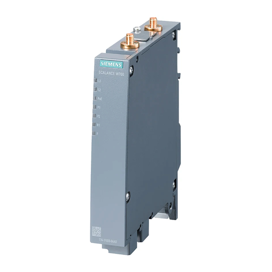
Description of the device Description of the device SCALANCE W774-1 /W734-1 RJ45 ① Antenna connector R1A1 ② PLUG slot / RESET button ③ Antenna connector R1A2 ④ LEDs ⑤ Ethernet connector P2 (PoE capability) ⑥ Ethernet connector P1 ⑦ Connector for power supply (L1, L2) ⑧... -
Page 14: Structure Of The Type Designation
Description of the device 3.2 Structure of the type designation SCALANCE W774-1 /W734-1 M12 ① Antenna connector R1A1 ② PLUG slot / RESET button ③ Antenna connector R1A2 ④ LEDs ⑤ Ethernet connector P2 (PoE capability) ⑥ Ethernet connector P1 ⑦... -
Page 15: Components Of The Product
• 1 screw for mounting on an S7-300 standard rail or S7-1500 standard rail • SIMATIC NET Industrial Wireless LAN CD Please check that the consignment you have received is complete. If the consignment is incomplete, contact your supplier or your local Siemens office. Accessories PLUG... - Page 16 Description of the device 3.4 Accessories M12 data plug-in connector Component Description Article number IE FC M12 M12 data plug-in connector for IE 1 connector per 6GK1901-0DB20-6AA0 PLUG PRO FC TP cables 2x2, IP65/67, D- package coded, axial cable outlet 8 connectors per 6GK1901-0DB20-6AA8 package...
- Page 17 Description of the device 3.4 Accessories Cabinet feedthrough Component Description Article number IE M12 PANEL Cabinet feedthrough for conversion from M12 6GK1901-0DM20-2AA5 FEEDTHROUGH connector technology (D-coded, IP65) to RJ-45 connector technology (IP20) pack of 5 IE M12 PANEL Cabinet feedthrough for conversion from M12 6GK1901-0DM30-2AA5 FEEDTHROUGH connector technology (D-coded, IP65) to M12...
-
Page 18: Flexible Connecting Cables And Antennas
Description of the device 3.4 Accessories Socket Component Description Article number IE POWER Socket for the 24 VDC power supply. 4-pin, A-coded 6GK1907-0DC10-6AA3 M12 CABLE pack of 3 CONNECTOR Lightning protection Component Description Article number LP798-1N Lighting protector with N/N female/female connect- 6GK5798-2LP00-2AA6 or with gas discharge technology LP798-2N... - Page 19 Description of the device 3.4 Accessories For railway applications, the following connecting cable are available: Length Article number 6XV1875-5TH10 6XV1875-5TH20 6XV1875-5TH50 Flexible connecting cable N-Connect/N-Connect Flexible connecting cable for connecting an antenna to a SCALANCE W device with N- Connect connectors. Preassembled with two N male connectors: Length Article number...
-
Page 20: Antennas
When you select an antenna, keep in mind the national approvals for your device. You will find more detailed information in Wireless approvals (https://www.siemens.com/wireless-approvals). The SCALANCE W1788-2IA uses internal omni antennas (3/4 dBi at 2.4 GHz or 5 GHz). Type... - Page 21 Description of the device 3.4 Accessories Type Properties Article number ANT795-4MD Omnidirectional antenna, 3/5 dBi, 2.4 GHz 6GK5795-4MD00-0AA3 and 5 GHz, IP65, N-Connect male for di- rect installation on the device, 90° con- nector. ANT795-4MX Omnidirectional antenna, 2/2.5 dBi, 2.4 6GK5795-4MX00-0AA0 GHz and 5 GHz, IP69K, N-Connect male ANT795-6DC...
-
Page 22: Led Display
Description of the device 3.5 LED display LED display Information on operating status and data transfer On the front of the housing, several LEDs provide information on the operating status of the device: Color Meaning Power supply L1 too low. Green Power supply L1 is applied. - Page 23 Description of the device 3.5 LED display Color Meaning There is no connection over the Ethernet port P1. Green There is a connection over the Ethernet port P1 (link). Flashing green Data transfer over the Ethernet interface P1. and yellow The WLAN interface 1 is deactivated.
-
Page 24: Reset Button
Description of the device 3.6 Reset button Color Meaning Flashing red Firmware on PLUG: The device is performing a firmware update or downgrade. Interval: 2000 ms on / 200 ms off A competing radar signal was found on all enabled channels. Simultaneous R1 yellow flash- Flashing yellow The port LEDs flash for detection of device location. - Page 25 Description of the device 3.6 Reset button Functions of the reset button The reset button has the following functions: • Restart of the device To restart the device, press the Reset button briefly. Note If you make changes to the configuration and restart immediately afterwards with the reset button, the changes may be lost.
- Page 26 Description of the device 3.6 Reset button • Resetting the device to the factory defaults The device can be reset to the factory defaults during operation. You will find more detailed information in the configuration manual in Resetting the device to factory defaults.
-
Page 27: Mounting
Mounting CAUTION Minimum distance to antennas Fit the device so that there is a minimum clearance of 20 cm between antennas and persons. WARNING If a device is operated in an ambient temperature of more than 50 °C, the temperature of the device housing may be higher than 70 °C. -
Page 28: Wall Mounting
Mounting 4.1 Wall mounting Wall mounting Drilling template The location of the holes for mounting the SCALANCE W774/W734 on a wall is shown in the following figure: SCALANCE W774-1 /W734-1 Operating Instructions, 07/2020, C79000-G8976-C325-14... - Page 29 Mounting 4.1 Wall mounting Procedure 1. Prepare the drill holes for wall mounting. For the precise dimensions, refer to the drilling template. 2. Secure the device to the wall with two screws (M4). The screws are not supplied with the device. The type and length of the screws depend on the type of wall.
-
Page 30: Installing On An S7-300 Standard Rail
Mounting 4.2 Installing on an S7-300 standard rail Installing on an S7-300 standard rail Procedure WARNING Danger of injury by falling objects When used in an area with heavy load, the device is not adequately supported on an S7-300 standard rail. Under such conditions, the device can come out of the mounting. If you use the device in a heavy load area, mount it on an S7-1500 mounting rail or on the wall. -
Page 31: Installing On An S7-1500 Standard Rail
Mounting 4.3 Installing on an S7-1500 standard rail Installing on an S7-1500 standard rail Procedure Follow the steps below to fit the SCALANCE W774/W734 to an S7-1500 standard rail: 1. Place the device on the upper edge of the S7-1500 standard rail as shown in the figure. 2. -
Page 32: Installing On A Din Rail / Removing
Mounting 4.4 Installing on a DIN rail / removing Installing on a DIN rail / removing Procedure for installation Follow the steps below to fit the SCALANCE W774/W734 to a DIN rail: 1. Place the device on the upper edge of the DIN rail as shown in the figure. 2. - Page 33 Mounting 4.4 Installing on a DIN rail / removing Procedure when removing Follow the steps below to remove the SCALANCE W774/W734 from a DIN rail: 1. Turn off the power to the device. 2. Disconnect all connected cables. 3. Pull the DIN rail slider down with a screwdriver. 4.
- Page 34 Mounting 4.4 Installing on a DIN rail / removing SCALANCE W774-1 /W734-1 Operating Instructions, 07/2020, C79000-G8976-C325-14...
-
Page 35: Connection
Connection Safety notices When connecting up the device, keep to the safety notices listed below. WARNING EXPLOSION HAZARD SUBSTITUTION OF COMPONENTS MAY IMPAIR SUITABILITY FOR CLASS I, DIVISION 2 OR ZONE 2. WARNING EXPLOSION HAZARD DO NOT OPEN WHEN ENERGIZED. Note Strain relief for the Ethernet cables In order to avoid mechanical stress on the Ethernet cables and resulting interruption of... -
Page 36: Lightning Protection, Power Supply And Grounding
Connection 5.1 Lightning protection, power supply and grounding Lightning protection, power supply and grounding Lightning protection WARNING Danger due to lightning strikes Antennas installed outdoors must be within the area covered by a lightning protection system. Make sure that all conducting systems entering from outdoors can be protected by a lightning protection potential equalization system. - Page 37 Connection 5.1 Lightning protection, power supply and grounding Supply voltage WARNING Safety extra low voltage The equipment is designed for operation with Safety Extra-Low Voltage (SELV) by a Limited Power Source (LPS). This means that only SELV / LPS (Limited Power Source) complying with IEC 60950-1 / EN 60950-1 / VDE 0805-1 must be connected to the power supply terminals or the power supply unit for the equipment power supply must comply with NEC Class 2, as described by the National Electrical Code (r) (ANSI / NFPA 70).
-
Page 38: Power Supply
Connection 5.2 Power supply General notes on use according to ATEX and IECEx WARNING EXPLOSION HAZARD DO NOT CONNECT OR DISCONNECT EQUIPMENT WHEN A FLAMMABLE OR COMBUSTIBLE ATMOSPHERE IS PRESENT. General notes on use in hazardous areas according to UL-HazLoc WARNING EXPLOSION HAZARD You may only connect or disconnect cables carrying electricity when the power supply... - Page 39 Connection 5.2 Power supply SCALANCE W774/W734 RJ-45 For the power supply, there are two options with the SCALANCE W774/W734: • Direct feed in via the four-pin socket (position ①) For the direct feed-in power supply use copper cables with the following properties: –...
- Page 40 Connection 5.2 Power supply SCALANCE W774 M12 EEC For the power supply, there are two options with the SCALANCE W774 M12 EEC: • Direct feed in via the four-pin M12 socket (position ①) – Round cable cross-section with 6 to 8 mm diameter. –...
-
Page 41: Ethernet
Connection 5.3 Ethernet Power over Ethernet The two following variants are available for power supply via an Ethernet cable: • IEEE 802.3at type 1 (IEEE 802.3af) On an 8-wire Fast Ethernet cable, the power is supplied via the free data wires 4, 5, 7 and 8. - Page 42 Connection 5.3 Ethernet SCALANCE W774/W734 RJ-45 ① Ethernet interface P1 ② Ethernet interface P2 The power can also be supplied via this interface (Power over Ethernet). SCALANCE W774/W734 M12 EEC ① Ethernet interface P1 ② Ethernet interface P2 The power can also be supplied via this interface (Power over Ethernet). The four-pin connecting socket has the following pin assignment: Assignment SCALANCE W774-1 /W734-1...
-
Page 43: Antenna Connectors
Connection 5.4 Antenna connectors Antenna connectors The SCALANCE W774/W734 has two antenna connectors of the type R-SMA located on the top of the device. ① Antenna connector R1 A1 ② Antenna connector R1 A2 SCALANCE W774-1 /W734-1 Operating Instructions, 07/2020, C79000-G8976-C325-14... - Page 44 Connection 5.4 Antenna connectors Procedure Follow the steps below to connect a cable for an external antenna to a SCALANCE W774/734: 1. Insert the connector on the antenna cable into the R-SMA socket and tighten the sleeve nut of the plug on the socket (key size SW8, tightening torque 1 Nm). If you only use one antenna, you need to connect this to the device via antenna connector R1 A1 (position ①).
-
Page 45: Replacing The Plug (C-Plug Or Key-Plug)
Connection 5.5 Replacing the PLUG (C-PLUG or KEY-PLUG) NOTICE UL approval only for use in buildings Within the area of authority of the NEC and CEC, the SCALANCE W770/W730 devices and the antennas connected to them may only be used in a closed building. For this reason, do not lead antennas into the outdoor area if you need to meet UL requirements. - Page 46 Connection 5.5 Replacing the PLUG (C-PLUG or KEY-PLUG) How it works The device supports the following modes of operation: • Without PLUG The device saves the configuration data in the internal memory. This mode is active when no PLUG is inserted. •...
- Page 47 Connection 5.5 Replacing the PLUG (C-PLUG or KEY-PLUG) Removing the PLUG Figure 5-2 Position of the slot for PLUG on the top of the SCALANCE W774/734 Follow the steps below to remove a PLUG from the device: 1. Turn off the power to the device. 2.
-
Page 48: Grounding
Connection 5.6 Grounding Inserting the PLUG Follow the steps below to insert a PLUG in the device: 1. Turn off the power to the device. 2. Release the screw slot cover (position ①) and swing the slot cover to the side (position ②). -
Page 49: Upkeep And Maintenance
Upkeep and maintenance Device configuration with PRESET-PLUG Please not the additional information and security notes in the operating instructions of your device. NOTICE Do not remove or insert a PLUG during operation A PLUG may only be removed or inserted when the device is turned off. Note Support as of V6.0 The PRESET-PLUG functionality is supported as of firmware version V6.0. - Page 50 Upkeep and maintenance 6.1 Device configuration with PRESET-PLUG Procedure 1. Start the remote configuration using Telnet (CLI) and log on with a user with the "admin" role. 2. Change to the Global configuration mode with the command "configure terminal". 3. You change to the PLUG configuration mode with the "plug" command. 4.
-
Page 51: Restoring The Factory Settings
Upkeep and maintenance 6.2 Restoring the factory settings Note Restore factory defaults and restart with a PRESET PLUG inserted If you reset a device to the factory defaults, when the device restarts an inserted PRESET PLUG is formatted and the PRESET PLUG functionality is lost. You then need to create a new PRESET PLUG. -
Page 52: Firmware Update Via Wbm Or Cli Not Possible
Upkeep and maintenance 6.3 Firmware update via WBM or CLI not possible To reset the device to the factory defaults during the startup phase, follow the steps below: 1. Turn off the power to the device. 2. Loosen the screws of the cover. 3. - Page 53 Upkeep and maintenance 6.3 Firmware update via WBM or CLI not possible Solution You can then also assign firmware to a SCALANCE W using TFTP. Follow the steps below to load new firmware using TFTP: 1. Turn off the power to the device. 2.
- Page 54 Upkeep and maintenance 6.3 Firmware update via WBM or CLI not possible SCALANCE W774-1 /W734-1 Operating Instructions, 07/2020, C79000-G8976-C325-14...
-
Page 55: Technical Data
Technical data Technical specifications W774/W734 RJ-45 The following technical specifications apply to the following devices: • SCALANCE W774-1 RJ-45 • SCALANCE W734-1 RJ-45 Note You will find detailed information on the transmit power and receiver sensitivity in the document "Performance data 802.11 abgn SCALANCE W770/W730" on the supplied data medium (REF_W770-RadioInterface.pdf). - Page 56 Technical data 7.1 Technical specifications W774/W734 RJ-45 Technical specifications Permitted cable lengths (Ethernet) (Alternative combinations per length range) IE TP torsion cable 0 ... 55 m 0 ... 45 m + 10 m TP cord IE FC TP marine cable 0 ...
-
Page 57: Technical Specifications W774 M12
Technical data 7.2 Technical specifications W774 M12 Technical specifications Degree of protection IP code IP30 Dimensions and weight Dimensions W x H x D 26 x 156 x 127 mm (height without antenna connector 147 Weight 520 g Installation options Direct Wall mounting With additional holding plate... - Page 58 Technical data 7.2 Technical specifications W774 M12 Technical specifications Class Class 2 * Mode Mode A (phantom power) Attachment to Industrial Ethernet Quantity Design M12 socket Properties Half duplex/full duplex, autocrossover, autonegotiation, autosensing, PoE, float- Permitted cable lengths (Ether- (Alternative combinations per length range) net) IE TP torsion cable 0 ...
- Page 59 Technical data 7.2 Technical specifications W774 M12 Technical specifications Permitted ambient conditions Ambient temperature During operation with the rack in- -30 ℃ to +65 ℃ stalled horizontally / vertically During storage -40 ℃ to +85 ℃ During transportation -40 ℃ to +85 ℃ Relative humidity During operation ≤...
- Page 60 Technical data 7.2 Technical specifications W774 M12 SCALANCE W774-1 /W734-1 Operating Instructions, 07/2020, C79000-G8976-C325-14...
- Page 61 Dimension drawings SCALANCE W774/734 RJ-45 SCALANCE W774-1 /W734-1 Operating Instructions, 07/2020, C79000-G8976-C325-14...
- Page 62 Dimension drawings SCALANCE W774 M12 EEC SCALANCE W774-1 /W734-1 Operating Instructions, 07/2020, C79000-G8976-C325-14...
- Page 63 Approvals You will find the approvals of the products in the reference work "Approvals SCALANCE W700 802.11n" on the Internet pages of Siemens Industry Online Support: • Using the search function at Siemens Industry Online Support (https://support.industry.siemens.com/cs/gb/en/) • Using the search function at Industrial communication (https://support.industry.siemens.com/cs/gb/en/ps/15859/cert)
- Page 64 Approvals SCALANCE W774-1 /W734-1 Operating Instructions, 07/2020, C79000-G8976-C325-14...
- Page 65 Index Antenna cables, 18 Grounding, 37 Antennas, 18 Connectors, 43 Directional antenna, 20 Dual directional antenna with linear Interfaces, 55, 57 polarization, 20 Dual-band directional antenna with linear polarization, 21 Helical antenna, 20 MIMO antenna, 21 LED display, 22 Omnidirectional antenna, 20 Lightning protection, 36 Article numbers, 5 Loading firmware, 24...
- Page 66 Index Type designations, 14 SCALANCE W774-1 /W734-1 Operating Instructions, 07/2020, C79000-G8976-C325-14...