Table of Contents
Advertisement
Quick Links
Advertisement
Table of Contents

Related Manuals for Siemens SIMATIC PN/CAN LINK


Summary of Contents for Siemens SIMATIC PN/CAN LINK
- Page 2 SIMATIC PN/CAN LINK Introduction Safety instructions SIMATIC New properties/functions System overview Network transitions SIMATIC PN/CAN LINK Functions Application planning Operating Instructions Mounting/Extending Connecting Commissioning Configuring/Programming Diagnostics Maintenance and service Technical specifications Appendix 03/2022 A5E39895388-AC...
- Page 3 Note the following: WARNING Siemens products may only be used for the applications described in the catalog and in the relevant technical documentation. If products and components from other manufacturers are used, these must be recommended or approved by Siemens. Proper transport, storage, installation, assembly, commissioning, operation and maintenance are required to ensure that the products operate safely and without any problems.
-
Page 4: Table Of Contents
5.1.3 CANopen Slave ........................54 5.1.3.1 Object dictionary ....................... 55 5.1.3.2 State model ........................56 5.1.3.3 Control and status information ................... 59 5.1.3.4 Monitoring functions ......................62 5.1.4 Response to errors ......................63 SIMATIC PN/CAN LINK Operating Instructions, 03/2022, A5E39895388-AC... - Page 5 Configuring in the TIA Portal .................... 123 10.3 Configuring CAN transparent ................... 129 10.3.1 Overview ......................... 129 10.3.2 Configuring in the TIA Portal .................... 130 10.4 Programming ........................136 10.4.1 PLC tags........................... 136 SIMATIC PN/CAN LINK Operating Instructions, 03/2022, A5E39895388-AC...
- Page 6 Contact address ....................... 163 Licenses ........................... 163 Service & Support ......................164 A.4.1 Technical Support ......................164 A.4.2 Siemens Industry Online Support ..................164 A.4.3 Online catalog and ordering system ................. 164 Glossary ............................. 165 Index ..............................168 SIMATIC PN/CAN LINK...
-
Page 7: Introduction
• Knowledge of working with the PROFINET fieldbus • In-depth knowledge of the CAN or CANopen communication protocols • General knowledge in the field of automation technology • General knowledge of communication networks SIMATIC PN/CAN LINK Operating Instructions, 03/2022, A5E39895388-AC... - Page 8 Introduction 1.1 Preface Trademarks SIMATIC is a registered trademark of Siemens AG. ® History Edition Note 03/2017 First edition 03/2018 Addition of naming scheme for generated PLC tags; Minor improvements and additions 01/2022 Addition of the "Simple slave functionality" Minor improvements and additions Naming conventions The term "PN/CAN LINK"...
-
Page 9: Documentation Guide
The latest manuals for SIMATIC products are available for download free of charge from the Internet (https://support.industry.siemens.com/cs/ww/en/ps/man). The information system of the TIA Portal also helps you configure and program your automation system and the PN/CAN LINK. SIMATIC PN/CAN LINK Operating Instructions, 03/2022, A5E39895388-AC... -
Page 10: Safety Instructions
Observe the safety instructions on the inside front cover of this documentation. SIMATIC PN/CAN LINK devices correspond to the approvals printed on the type plate. If you have questions about whether it is permissible to install the device in the planned environment, please contact your service representative. - Page 11 • Before carrying out any work on the device or on connected components, make sure that the installation is in a zero-voltage state. • Use cable types with UL approval for UL-approved systems. SIMATIC PN/CAN LINK Operating Instructions, 03/2022, A5E39895388-AC...
-
Page 12: Security Information
Siemens' products and solutions undergo continuous development to make them more secure. Siemens strongly recommends that product updates are applied as soon as they are available and that the latest product versions are used. Use of product versions that are no longer supported, and failure to apply the latest updates may increase customers' exposure to cyber threats. -
Page 13: New Properties/Functions
HSP/FW versions TIA Portal HSP required HSP version Note version version V14 SP1 HSP_V14_0197_001_Link_PN_CAN_1 V1.0 "Update module description" necessary V15.1 HSP_V15_1_0197_001_Link_PN_CAN V1.0 _1.0 HSP_V16_0197_001_Link_PN_CAN_1 V1.0 V1.0 HSP_V17_0358_001_Link_PN_CAN_2 V1.0; V2.0 "Simple slave functionality" included SIMATIC PN/CAN LINK Operating Instructions, 03/2022, A5E39895388-AC... -
Page 14: Changes Compared To The Previous Version
TIA Portal project. When a downgrade is required, you must create a new PN/CAN LINK module for V1.0 within a TIA Portal project. In this case, however, the "Simple slave functionality" is not available. You can perform a firmware update/firmware downgrade without any restrictions. SIMATIC PN/CAN LINK Operating Instructions, 03/2022, A5E39895388-AC... - Page 15 • Check box Enable additional diagnostics alarms When you disable this option, the device does not send diagnostic alarms related to the operating mode (CANopen Manager, CANopen Slave and CAN transparent). Both error LEDs remain off. SIMATIC PN/CAN LINK Operating Instructions, 03/2022, A5E39895388-AC...
- Page 16 If you have made parameter changes before setting the "No NMT / Layer 2 slave" option, these values are retained. However, they have no effect on the actual configuration of the node in the system. SIMATIC PN/CAN LINK Operating Instructions, 03/2022, A5E39895388-AC...
- Page 17 • Check box Enable additional diagnostics alarms When you disable this option, the device does not send diagnostic alarms related to the operating mode (CANopen Manager, CANopen Slave and CAN transparent). Both error LEDs remain off. SIMATIC PN/CAN LINK Operating Instructions, 03/2022, A5E39895388-AC...
- Page 18 The "Boolean" data type is now available for transmit/receive data OD and transmit/receive messages. Editable OD table (manually defined object dictionary) You can find additional information in the section "Handling of the OD table" in the section Configuration in the TIA Portal (Page 108). SIMATIC PN/CAN LINK Operating Instructions, 03/2022, A5E39895388-AC...
- Page 19 The status of a node can have the following values (according to CiA standard "CiA 302 Part 2"): • 0 = unknown state or NMT/BOOTUP • 1 = node missing • 4 = NMT/STOPPED • 5 = NMT/OPERATIONAL • 127 = NMT/PRE-OPERATIONAL SIMATIC PN/CAN LINK Operating Instructions, 03/2022, A5E39895388-AC...
-
Page 20: Installation And Handling Of The New Hsp
HSP_V17_0358_001_Link_PN_CAN_V2.0. You can configure a PN/CAN LINK with firmware version V1.0 using the same HSP. If necessary, you can download and install the "HSP_V17_0358_001_Link_PN_CAN_V2.0" from Siemens Industry Online Support. You can find the Hardware Support Packages (HSP) as a download on the Internet (https://support.industry.siemens.com/cs/us/en/view/72341852). - Page 21 TIA Portal project. When a downgrade is required, you must create a new PN/CAN LINK module for V1.0 within a TIA Portal project. In this case, however, the "Simple slave functionality" is not available. You can perform a firmware update/firmware downgrade without any restrictions. SIMATIC PN/CAN LINK Operating Instructions, 03/2022, A5E39895388-AC...
- Page 22 When selecting the PN/CAN LINK, you can choose the desired firmware version in the HW catalog. Figure 3-2 Selecting a firmware version in the HW catalog The new "Simple slave functionality" is only available as of version V2.0. SIMATIC PN/CAN LINK Operating Instructions, 03/2022, A5E39895388-AC...
- Page 23 2. To upgrade the PN/CAN LINK, click the "Change firmware version" button under "General > Catalog information". 3. Confirm the "Change device - PN/CAN LINK" dialog with "OK". 4. As a downgrade from V2.0 to V1.0 is not possible, the "Change firmware version" button is disabled afterwards. SIMATIC PN/CAN LINK Operating Instructions, 03/2022, A5E39895388-AC...
- Page 24 3.3 Installation and handling of the new HSP 5. Use the "Simple slave functionality". 6. Make sure that the device has the correct firmware version 2.0 before loading the changed configuration. Figure 3-3 Changing the firmware version SIMATIC PN/CAN LINK Operating Instructions, 03/2022, A5E39895388-AC...
- Page 25 PN/CAN LINK was updated successfully. Now you can use the PN/CAN LINK with its OD entries and nodes as needed. SIMATIC PN/CAN LINK Operating Instructions, 03/2022, A5E39895388-AC...
- Page 26 • Use the "Update module description" button if you want to use firmware version V1.0. • Use the "Update module description" and "Change firmware version" buttons if you want to use firmware version V2.0. Figure 3-5 Update module description Figure 3-6 Changing the firmware version SIMATIC PN/CAN LINK Operating Instructions, 03/2022, A5E39895388-AC...
-
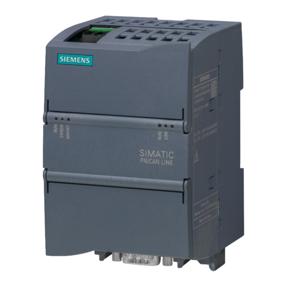
Page 27: System Overview
Figure 4-1 SIMATIC PN/CAN LINK The SIMATIC PN/CAN LINK is a communication gateway and allows for the connection of SIMATIC controllers to the CAN fieldbus over PROFINET. This connection enables the exchange of information and data between PROFINET and CAN. - Page 28 • The CAN side supports baud rates from 50 kBaud up to 1000 kBaud. • The maximum permissible cable length of the CAN network is up to 1000 m (dependent on data transmission rate, cable cross-section, number of nodes). SIMATIC PN/CAN LINK Operating Instructions, 03/2022, A5E39895388-AC...
- Page 29 • The PN/CAN LINK can be used as an "NMT slave" according to "CiA 302 Part 2". When the PN/CAN LINK is an NMT slave, another CANopen Manager configures the OD and thus which data is exchanged with which other devices. SIMATIC PN/CAN LINK Operating Instructions, 03/2022, A5E39895388-AC...
- Page 30 • The PN/CAN LINK can forward data from received CAN messages to the S7 controller as PROFINET input data. • The PN/CAN LINK can send CAN messages with PROFINET output data of the S7 controller. SIMATIC PN/CAN LINK Operating Instructions, 03/2022, A5E39895388-AC...
-
Page 31: System Configuration
PN/CAN LINK. The TIA Portal is used for configuring. A corresponding HSP is available for this purpose. The configuration of CANopen slaves is based on device description files (EDS) that are imported. SIMATIC PN/CAN LINK Operating Instructions, 03/2022, A5E39895388-AC... -
Page 32: System Requirements
• Windows PC (for configuring, commissioning and diagnostics) • TIA Portal V14 or higher, you can find the required HSP on the Internet (https://support.industry.siemens.com/cs/us/en/view/72341852) You can find an overview of all HSP/firmware versions in the chapter Version overview (Page 12). SIMATIC PN/CAN LINK Operating Instructions, 03/2022, A5E39895388-AC... -
Page 33: Design
Status LEDs device + PROFINET See also 24 V DC power supply (Page 89) Operating state of the PN/CAN LINK / PROFINET diagnostics (Page 139) Connecting PROFINET (Page 92) Connecting the CAN bus (Page 94) SIMATIC PN/CAN LINK Operating Instructions, 03/2022, A5E39895388-AC... -
Page 34: Functions
The following overview diagram shows the correlations in the communication between CAN and PROFINET. Only available in Manager mode Only available in Slave mode Figure 5-1 PN/CAN LINK principle of communication with CANopen SIMATIC PN/CAN LINK Operating Instructions, 03/2022, A5E39895388-AC... -
Page 35: Object Dictionary
The following actions are being executed in the process: • The default value is written to the OD. • The information whether the OD entry has been written by the CANopen side once before is reset. SIMATIC PN/CAN LINK Operating Instructions, 03/2022, A5E39895388-AC... -
Page 36: Process Data Objects (Pdo)
"SYNC". Event-controlled transmit-PDOs with transmission type 254 (manufacturer-specific) and transmission type 255 (application-profile specific) are also transmitted during the transition to the NMT state "Operational". SIMATIC PN/CAN LINK Operating Instructions, 03/2022, A5E39895388-AC... -
Page 37: Service Data Objects (Sdo)
Is also transmitted when the NMT Manager tries to set the PN/CAN LINK to "Operational" state while the desired state transmitted in the cyclic data from the S7 controller is still "OFF". The EMCY messages always use the default COB ID intended for this purpose. SIMATIC PN/CAN LINK Operating Instructions, 03/2022, A5E39895388-AC... -
Page 38: Heartbeat / Node Guarding
CANopen side, and the fault reaction configured or specified in the OD (0x1029) is executed. The possible fault reactions for manager / slave are available in the following sections: • CANopen Manager: Monitoring functions (Page 52) • CANopen Slave: Monitoring functions (Page 62) SIMATIC PN/CAN LINK Operating Instructions, 03/2022, A5E39895388-AC... -
Page 39: Sync Messages
0x1006 is rejected if SYNC transmitter bit is detected in OD 0x1005. Note The SYNC function only has an effect on the CANopen side. It is not used to synchronize the data transmission on the CANopen side and the PROFINET side. SIMATIC PN/CAN LINK Operating Instructions, 03/2022, A5E39895388-AC... -
Page 40: Data Exchange Between Controller And Pn/Can Link
The user can reset the CANopen side in the PN/CAN LINK from the S7 program using a reset bit. Detailed information on the control and status information is available here: CANopen Manager (Page 46) CANopen Slave (Page 59) SIMATIC PN/CAN LINK Operating Instructions, 03/2022, A5E39895388-AC... - Page 41 Status byte input Status byte output data data PN/CAN LINK (rack 0, slot 0) Interface Port 1 Port 2 CANopen network Transmit data/transmit message Receive data/receive message Transmit and receive data Example with PN/CAN LINK SIMATIC PN/CAN LINK Operating Instructions, 03/2022, A5E39895388-AC...
- Page 42 S7 user program can access with the help of the acyclic PROFINET IO services RDREC (Read data record) and WRREC (Write data record). Detailed information can be found under Acyclic data exchange between controller and PN/CAN LINK (Page 49). SIMATIC PN/CAN LINK Operating Instructions, 03/2022, A5E39895388-AC...
-
Page 43: Conversion Of Data Formats Between Profinet And Canopen
UNSIGNED 32 Unsigned 64 UNSIGNED 64 Float 32 / float REAL 32 Float 64 / double REAL 64 Bool Bool None Note The "Bool" data type is only available in PN/CAN LINK 2.0. SIMATIC PN/CAN LINK Operating Instructions, 03/2022, A5E39895388-AC... -
Page 44: Canopen Manager
The state model in "CANopen Manager" mode is based on the NMT state model described in the CiA standard "CiA 301" taking into account the network management function. Figure 5-3 State model CANopen Manager SIMATIC PN/CAN LINK Operating Instructions, 03/2022, A5E39895388-AC... - Page 45 CAN network All slaves connected via CANopen and the PN/CAN LINK are in the "Operational" state. Operational CAN network All slaves connected via CANopen and the PN/CAN LINK are in the "Stopped" state. Stopped SIMATIC PN/CAN LINK Operating Instructions, 03/2022, A5E39895388-AC...
- Page 46 (NMT Master error behavior is "Restart of the PN/CAN LINK"). • Reset bit contained in the cyclic data from the S7 controller • Reconfiguration by the S7 controller • Error during boot-up (except heartbeat/node-guarding errors) SIMATIC PN/CAN LINK Operating Instructions, 03/2022, A5E39895388-AC...
-
Page 47: Control And Status Information
NMT command "to all" in this case. An NMT command is sent instead to each fully booted slave individually. As soon as the other slaves are completely booted, they are also switched to "Operational" with an NMT command. SIMATIC PN/CAN LINK Operating Instructions, 03/2022, A5E39895388-AC... - Page 48 PDO since the last reset. All receive OD entries have been updated at least once by a PDO since the last reset. SIMATIC PN/CAN LINK Operating Instructions, 03/2022, A5E39895388-AC...
- Page 49 For values made up of multiple bits, the first bit is the MSB and the last bit is the LSB. Example: Bit 1 ... 0 = "2" means that bit 0 = "0" and bit 1 = "1". SIMATIC PN/CAN LINK Operating Instructions, 03/2022, A5E39895388-AC...
-
Page 50: Acyclic Data Exchange Between Controller And Pn/Can Link
Number of bytes to be written with SDO (Big Endian), permitted are 1 ... 128 (Big Endian) 7 ... <END> <missing> Bytes to be written WRREC access can be successful or return one of the following error codes. SIMATIC PN/CAN LINK Operating Instructions, 03/2022, A5E39895388-AC... - Page 51 6 and LSB in byte 9) 10 ... 11 Number of read bytes (Big Endian) <missing> (only available when status code = OK ) 12 ... <END> Data <missing> (only available when status code = OK ) SIMATIC PN/CAN LINK Operating Instructions, 03/2022, A5E39895388-AC...
- Page 52 The SDO access for the PN/CAN LINK is completed with the finished RDREC. The device is then ready for a new SDO command. An additional RDREC without preceding successful WRREC returns an error code. SIMATIC PN/CAN LINK Operating Instructions, 03/2022, A5E39895388-AC...
-
Page 53: Monitoring Functions
"Monitoring time" and "Repetition factor" can be set. The PN/CAN LINK can be both a transmitter and a receiver. Note As of firmware version V2.0 The "Node Guarding" function can be disabled by setting the Repetition factor or the Monitoring time to "0". SIMATIC PN/CAN LINK Operating Instructions, 03/2022, A5E39895388-AC... - Page 54 ERROR LED lights up. • When the "Enable diagnostic alarms for not mandatory nodes" check box is cleared, no error messages are sent to the diagnostic buffer and the ERROR LED remains off. SIMATIC PN/CAN LINK Operating Instructions, 03/2022, A5E39895388-AC...
-
Page 55: Canopen Slave
OD of the PN/CAN LINK during boot-up by the CANopen Manager responsible for the CANopen network via SDOs. Note Retentive storage in the PN/CAN LINK of the configuration received from a CANopen Manager in "CANopen Slave" mode is not supported. SIMATIC PN/CAN LINK Operating Instructions, 03/2022, A5E39895388-AC... -
Page 56: Object Dictionary
TX-PDO Mapping parameters 0x2xxx Entries for the process data to be exchanged with the S7 controller. Entries for input data, that is data that comes from the S7 controller, are "Read Only" in CANopen. SIMATIC PN/CAN LINK Operating Instructions, 03/2022, A5E39895388-AC... -
Page 57: State Model
The state model in "CANopen Slave" mode is based on the NMT state model described in the CiA standard "CiA 301". The figure below shows the states of the PN/CAN LINK in "CANopen Slave" mode. Figure 5-4 State model CANopen Slave SIMATIC PN/CAN LINK Operating Instructions, 03/2022, A5E39895388-AC... - Page 58 (e.g.: SYNC, SDO, Heartbeat) Operational Normal operation, all types of communication are active Stopped Only heartbeat / node guarding are active but device can still be controlled via NMT, "application OFF state" SIMATIC PN/CAN LINK Operating Instructions, 03/2022, A5E39895388-AC...
- Page 59 An NMT command from the CANopen Manager (depending on the command, transition to "Reset Application" or "Reset Communication" substate) • The reset bit from the S7 controller (transition to "Reset Application" substate) • Reconfiguration by the S7 controller (transition to "Reset Application" substate) SIMATIC PN/CAN LINK Operating Instructions, 03/2022, A5E39895388-AC...
-
Page 60: Control And Status Information
"Pre-Operational". Commands from the NMT master to change to the "Operational" state are ignored. The PN/CAN LINK can be switched by the NMT master via NMT command to the "Operational" state. SIMATIC PN/CAN LINK Operating Instructions, 03/2022, A5E39895388-AC... - Page 61 PDO since the last reset. All receive OD entries have been updated at least once by a PDO or SDO since the last reset. SIMATIC PN/CAN LINK Operating Instructions, 03/2022, A5E39895388-AC...
- Page 62 For values consisting of multiple bits, the first bit is the MSB and the last bit the LSB. Example: Bit 1 ... 0 = "2" means that bit 0 = "0" and bit 1 = "1". SIMATIC PN/CAN LINK Operating Instructions, 03/2022, A5E39895388-AC...
-
Page 63: Monitoring Functions
The following error responses are supported: Subindex Description value 0x00 Change to the "Pre-Operational" state only when the current state is "Operational" 0x01 Current state is retained, that is no response 0x02 Change to "Stopped" state SIMATIC PN/CAN LINK Operating Instructions, 03/2022, A5E39895388-AC... -
Page 64: Response To Errors
Bit is set in "any error situation", according to CiA standard "CiA 301", which means when a specific error bit is set and for errors that are not mapped to specific error bits. SIMATIC PN/CAN LINK Operating Instructions, 03/2022, A5E39895388-AC... - Page 65 The PN/CAN LINK signals its state in "CANopen Manager" mode and in "CANopen Slave" mode with the LEDs on the front of the housing. The meaning of the LEDs is described in section Operating state of the PN/CAN LINK / PROFINET diagnostics (Page 139). SIMATIC PN/CAN LINK Operating Instructions, 03/2022, A5E39895388-AC...
-
Page 66: Can Transparent
PN/CAN LINK state "ON" In this state the PN/CAN LINK participates in the CAN bus communication, that is it transmits and receives CAN frames unless the CAN controller is in Bus Off state. SIMATIC PN/CAN LINK Operating Instructions, 03/2022, A5E39895388-AC... - Page 67 Reconfiguration by S7 controller The PN/CAN LINK receives the necessary configuration data from the S7 controller. For the "receive message modules" the input data is preassigned according to the parameter assignment. PN/CAN LINK state is "OFF". SIMATIC PN/CAN LINK Operating Instructions, 03/2022, A5E39895388-AC...
-
Page 68: Can Messages
The sending and receiving of CAN messages from the S7 user program is possible using transmit and receive proxy modules. See: Cyclic data exchange between controller and PN/CAN LINK for programmed CAN messages (Page 71) SIMATIC PN/CAN LINK Operating Instructions, 03/2022, A5E39895388-AC... -
Page 69: Control And Status Information
This is the normal state. Everything is okay. 1) The error counters customary in CAN and the associated thresholds are internal functions that are not visible to the user. SIMATIC PN/CAN LINK Operating Instructions, 03/2022, A5E39895388-AC... - Page 70 For values made up of multiple bits, the first bit is the MSB and the last bit is the LSB. Example: Bit 1 ... 0 = 2 means: Bit 0 = "0" and bit 1 = "1". SIMATIC PN/CAN LINK Operating Instructions, 03/2022, A5E39895388-AC...
-
Page 71: Cyclic Data Exchange Between Controller And Pn/Can Link For Configured Can Messages
S7 controller. As long as there is at least one configured message ID from which a CAN message has not yet been received, a zero is transmitted to the S7 controller in the status bit. SIMATIC PN/CAN LINK Operating Instructions, 03/2022, A5E39895388-AC... -
Page 72: Cyclic Data Exchange Between Controller And Pn/Can Link For Programmed Can Messages
LINK. Any necessary adaptation to compensate for "endianness" must be made in the S7 user program. Note For values made up of multiple bits, the first bit is the MSB and the last bit is the LSB. SIMATIC PN/CAN LINK Operating Instructions, 03/2022, A5E39895388-AC... - Page 73 For 29-bit message IDs byte 1 bit 4 is the most significant bit and byte 4 bit 0 the least significant bit. 5-12 Data bytes In the order in which they are going to be sent SIMATIC PN/CAN LINK Operating Instructions, 03/2022, A5E39895388-AC...
- Page 74 The order of the data bytes in the received CAN messages is not changed in the PN/CAN LINK. Any necessary adaptation to compensate for "endianness" must be made in the S7 user program. SIMATIC PN/CAN LINK Operating Instructions, 03/2022, A5E39895388-AC...
- Page 75 Note: May only be evaluated when the transfer bit is "1". Number of data bytes in the received CAN message 0.4 ... The value range is 0 to 8. Note: May only be evaluated when the transfer bit is "1". SIMATIC PN/CAN LINK Operating Instructions, 03/2022, A5E39895388-AC...
- Page 76 2. When this happens, the first message is copied to the SIMATIC S7 controller and "Transfer" is set to "1". 3. Set "Receive enable" to "0" and wait until "Transfer" is set to "0". 4. Repeat the operation starting at step 1. SIMATIC PN/CAN LINK Operating Instructions, 03/2022, A5E39895388-AC...
- Page 77 16 filters with 4 bytes each for Criterion and Mask are permitted. If the number of written bytes is ≥ 128, the write access (WRREC) is rejected with PROFINET error code 0xDF80B100 and the filter remains unchanged. SIMATIC PN/CAN LINK Operating Instructions, 03/2022, A5E39895388-AC...
- Page 78 If less than 8 bytes are written or if bit 31 = "1" is true for "Criterion" for all filters, the receive proxy has "no valid receive filter". That is signaled in the corresponding bit in the input data for the S7 controller. SIMATIC PN/CAN LINK Operating Instructions, 03/2022, A5E39895388-AC...
-
Page 79: Response To Errors
In "CAN transparent" mode the PN/CAN LINK signals its state by means of the fieldbus LEDs on the front of the housing. The meaning of the LEDs is described in section Operating state of the PN/CAN LINK / PROFINET diagnostics (Page 139). SIMATIC PN/CAN LINK Operating Instructions, 03/2022, A5E39895388-AC... -
Page 80: Application Planning
• Proper grounding and wiring of the PN/CAN LINK is important for optimal operation and for sufficient immunity of your system and your application. SIMATIC PN/CAN LINK Operating Instructions, 03/2022, A5E39895388-AC... -
Page 81: Installation Location
• For horizontal mounting position: At least 35 mm above and below the PN/CAN LINK • For vertical mounting position: At least 35 mm to the left and right of the PN/CAN LINK Provide sufficient space for the connection of supply voltage, Ethernet and CAN bus. SIMATIC PN/CAN LINK Operating Instructions, 03/2022, A5E39895388-AC... - Page 82 PN/CAN LINK must be protected by an enclosure with the corresponding degree of protection. IP54 is a protection class that is generally used for electronic systems in heavily polluted environments and may be suitable for your application. SIMATIC PN/CAN LINK Operating Instructions, 03/2022, A5E39895388-AC...
- Page 83 UL regulations. The control cabinet / device connection box must satisfy the regulations regarding fire- protection housing. Ensure that all cables and leads that protrude externally are equipped with adequate strain relief. SIMATIC PN/CAN LINK Operating Instructions, 03/2022, A5E39895388-AC...
-
Page 84: Transportation
3. Check the device for transport damage by visual inspection. NOTICE Damage to the system Damaged parts can result in damage to the system. Do not use devices that show evidence of damage! SIMATIC PN/CAN LINK Operating Instructions, 03/2022, A5E39895388-AC... -
Page 85: Mounting/Extending
①) must always be in the default positions set at the factory. Otherwise the mounting sliders may warp if they are exposed to hot and humid ambient conditions for a long time. SIMATIC PN/CAN LINK Operating Instructions, 03/2022, A5E39895388-AC... - Page 86 Fasten the screw with the corresponding torque until the spring lock washer is pressed flat. Do not fasten the screws with excessive torque. Figure 7-2 Control panel mounting of the PN/CAN LINK SIMATIC PN/CAN LINK Operating Instructions, 03/2022, A5E39895388-AC...
-
Page 87: Connecting
When wiring the PN/CAN LINK, observe the wiring guidelines of your automation system (e.g. SIMATIC S7-1200, SIMATIC S7-1500, SIMATIC ET 200SP). Also observe the installation instructions and configuration guidelines for routing of the PROFINET cables. SIMATIC PN/CAN LINK Operating Instructions, 03/2022, A5E39895388-AC... - Page 88 • Observe the bending radii. CAUTION For system for UL approval: The cables must be specified for an ambient temperature of at least +75 °C. SIMATIC PN/CAN LINK Operating Instructions, 03/2022, A5E39895388-AC...
-
Page 89: Potential Ratios
PROFINET cables to a shield rail. The shields of the CAN interface are capacitively decoupled from the shields of the PROFINET interface to prevent compensating currents over the cable shields. Figure 8-1 Block diagram shielding SIMATIC PN/CAN LINK Operating Instructions, 03/2022, A5E39895388-AC... -
Page 90: 24 V Dc Power Supply
24 V supply for PN/CAN LINK (+) 24 V supply for PN/CAN LINK (-) Functional ground Permissible torques for screw terminal: • Minimum tightening torque: 0.5 Nm • Maximum tightening torque: 0.6 Nm SIMATIC PN/CAN LINK Operating Instructions, 03/2022, A5E39895388-AC... - Page 91 We recommend the Dehn Blitzductor BXT ML2 BD 180, article number 920 247 (on basis BXT BAS) or an equivalent protection element. Manufacturer: DEHN+SOEHNE GmbH+Co.KG, Hans-Dehn-Str.1, Postfach 1640, D-92306 Neumarkt, Germany The lightning protection module must be installed and used in accordance with the manufacturer's specifications. SIMATIC PN/CAN LINK Operating Instructions, 03/2022, A5E39895388-AC...
-
Page 92: Connecting The Functional Ground
EMC-compliant functional grounding • Use as short a stranded-wire conductor as possible with a large cross section. • Compliance with the technical specifications of the device is only assured with a correct functional ground connection. SIMATIC PN/CAN LINK Operating Instructions, 03/2022, A5E39895388-AC... -
Page 93: Connecting Profinet
To increase the mechanical stability, optimized retaining collars ② for the two Ethernet connectors are installed on the bottom part of the housing in the delivery state. These retaining collars are intended for the Siemens FastConnect connectors. NOTICE Make sure you observe the minimum bending radius of the Ethernet cable; otherwise the shield effect of the cable shield may be impaired. - Page 94 PN/CAN LINK. A restart of the PN/CAN LINK interrupts the Ethernet switch function. Existing Ethernet connections over the switch are interrupted for the duration of the PN/CAN LINK run-up. This can result in critical plant states. SIMATIC PN/CAN LINK Operating Instructions, 03/2022, A5E39895388-AC...
-
Page 95: Connecting The Can Bus
The connection CAN Ground to ground is necessary to ensure EMC stability. The common return (CAN_GND) may only be connected in one place to the ground potential in the CAN network. NOTICE EMC stability is only guaranteed with shielded CAN cables. SIMATIC PN/CAN LINK Operating Instructions, 03/2022, A5E39895388-AC... -
Page 96: Commissioning
1. Checking in the TIA Portal whether the "PN/CAN LINK" module exists in the hardware catalog. If necessary, download and install the HSP "HSP0197 PN/CAN LINK" from Siemens Service&Support (https://support.industry.siemens.com/cs/us/en/). Firmware version V2.0 supports new functions that are made available with the following Hardware Support Package (HSP): HSP_V17_0358_001_Link_PN_CAN_V2.0... - Page 97 In "CANopen Manager" mode, bit 2 must also be set to "1" in the control information transmitted from the S7-CPU to the PN/CAN LINK (see Control and status information (Page 46)). Result Successful commissioning of the PN/CAN LINK. SIMATIC PN/CAN LINK Operating Instructions, 03/2022, A5E39895388-AC...
-
Page 98: Configuring/Programming
The new functions mainly refer to using the CANopen Manager mode. Note TIA Portal Openness The PN/CAN LINK supports only mandatory attributes in TIA Portal Openness. When selecting the PN/CAN LINK, you can choose the desired firmware version in the HW catalog. SIMATIC PN/CAN LINK Operating Instructions, 03/2022, A5E39895388-AC... - Page 99 Configuring/Programming Figure 10-1 Selecting a firmware version in the HW catalog Or you can select the "Change firmware version" option for a PN/CAN LINK that has already been configured. SIMATIC PN/CAN LINK Operating Instructions, 03/2022, A5E39895388-AC...
- Page 100 Configuring/Programming Figure 10-2 Changing the firmware version SIMATIC PN/CAN LINK Operating Instructions, 03/2022, A5E39895388-AC...
-
Page 101: Configuring Canopen Manager
7. Create OD entries for the transmit and receive data to be exchanged in the manager module. 8. Define the corresponding receive PDOs and transmit PDOs in the manager module. 9. If necessary, make additional settings, such as heartbeat, node guarding and SYNC. 10.Check and compile the configuration. SIMATIC PN/CAN LINK Operating Instructions, 03/2022, A5E39895388-AC... -
Page 102: Configuration View In The Tia Portal
CPU and PN/CAN LINK are connected in the "Devices & networks" window with a green PN line ③. 4. Assign the parameters of the PROFINET interface of the PN/CAN LINK ④ according to the configuration of your PROFINET network. Figure 10-3 TIA Portal: Devices & networks SIMATIC PN/CAN LINK Operating Instructions, 03/2022, A5E39895388-AC... - Page 103 All settings for the CANopen Manager module of the PN/CAN LINK are made in slot 1. Setting the communication parameters Set the bus-specific parameters, for example, node ID and transmission rate. As of firmware version 2.0, you can set the parameters "max. SDO Timeout" and "max. BootUp Timeout". SIMATIC PN/CAN LINK Operating Instructions, 03/2022, A5E39895388-AC...
- Page 104 When you disable this option, the disconnection of the nodes from the CAN bus or error messages that are pending in the CANopen network are not sent to the diagnostic buffer and the ERROR LED remains off. SIMATIC PN/CAN LINK Operating Instructions, 03/2022, A5E39895388-AC...
- Page 105 Flag", which consists of 6 recessive bits. This signal does not destroy any other communication on the bus. The device is fully operational unless an error counter exceeds 255 and the device goes into the "Bus Off" state.) Figure 10-6 Setting the diagnostic parameters SIMATIC PN/CAN LINK Operating Instructions, 03/2022, A5E39895388-AC...
- Page 106 "Import EDS file..." ② button opens the corresponding file selection dialog. 3. As of firmware version 2.0, you can manually define the object dictionary (OD). For additional information about this function, refer to section "Handling of the OD table" below. SIMATIC PN/CAN LINK Operating Instructions, 03/2022, A5E39895388-AC...
- Page 107 Configuring/Programming 10.1 Configuring CANopen Manager Figure 10-8 Define object dictionary (as of firmware version 2.0) SIMATIC PN/CAN LINK Operating Instructions, 03/2022, A5E39895388-AC...
- Page 108 You perform the entire configuration in the corresponding menus and not in the OD table. Settings from the menus are not visible in the OD table. You can find additional information in the section "Handling of the OD table" below. SIMATIC PN/CAN LINK Operating Instructions, 03/2022, A5E39895388-AC...
- Page 109 Importing the EDS file 2. Manual creation of an object dictionary (OD) using the "Define object dictionary" button: A template is displayed in the "Object dictionary (OD)" menu. Figure 10-10 Defining the object dictionary SIMATIC PN/CAN LINK Operating Instructions, 03/2022, A5E39895388-AC...
- Page 110 You can delete existing rows by using the shortcut menu of a table row. If you are not sure whether you want to delete an entry, disable it. The entry will be ignored during the next configuration. Figure 10-12 Shortcut menu of a table row SIMATIC PN/CAN LINK Operating Instructions, 03/2022, A5E39895388-AC...
- Page 111 OD table. The CANopen Manager uses this data to configure the node during the boot-up phase and for verifying the correct values in the settings. SIMATIC PN/CAN LINK Operating Instructions, 03/2022, A5E39895388-AC...
- Page 112 • PDO assignable • Index.Subindex - You can only edit this column when you have added a new entry. It can no longer be edited once you press the "Apply and check data" button. SIMATIC PN/CAN LINK Operating Instructions, 03/2022, A5E39895388-AC...
- Page 113 "Index.Sub" field. If you want to change it, you have to delete the entry and add it again. 2. A check is performed to determine whether the object can be read or written to so that data exchange is possible. SIMATIC PN/CAN LINK Operating Instructions, 03/2022, A5E39895388-AC...
- Page 114 – When one of these ODs is not available in the EDS file or is not selected in the OD table, the "Loose configuration" check box is selected and disabled in the "CANopen node universal > Communication" menu. SIMATIC PN/CAN LINK Operating Instructions, 03/2022, A5E39895388-AC...
- Page 115 Creating an OD entry for transmit data in the Manager 1. Double-click "Transmit data object dictionary" ① in the HW catalog. This places an OD entry as a submodule in the "CANopen Manager" module. Figure 10-14 Creating a transmit data OD SIMATIC PN/CAN LINK Operating Instructions, 03/2022, A5E39895388-AC...
- Page 116 Repeat the above steps until all desired transmit data has been created in the OD of the Manager. Note You can create a maximum of 100 OD entries. This maximum number is independent of the distribution of entries between the transmit data OD and receive data OD. SIMATIC PN/CAN LINK Operating Instructions, 03/2022, A5E39895388-AC...
- Page 117 PDOs with the same COB ID are structured. Note The length of the transmit data assigned to a transmit PDO must match the length of the receive data in the corresponding receive PDO at the end of configuring. SIMATIC PN/CAN LINK Operating Instructions, 03/2022, A5E39895388-AC...
- Page 118 If you disable this option, all data from a received PDO with a length deviating from the standard is discarded and replaced with the value of the last valid PDO (last received PDO with the correct length). The CANopen Manager calls up an error message in the diagnostic buffer. SIMATIC PN/CAN LINK Operating Instructions, 03/2022, A5E39895388-AC...
- Page 119 CANopen Manager, are important because the control and status information is exchanged with the S7 program via these addresses. It is important for startup of the PN/CAN LINK that the control information transmitted here from the S7 program is set correctly. SIMATIC PN/CAN LINK Operating Instructions, 03/2022, A5E39895388-AC...
- Page 120 PN/CAN LINK. No errors or warnings are generated by the module. Figure 10-18 Disabling a node temporarily When such a node appears in the menu, it is marked as "(disabled)". SIMATIC PN/CAN LINK Operating Instructions, 03/2022, A5E39895388-AC...
- Page 121 10.1 Configuring CANopen Manager Figure 10-19 Node disabled Checking data consistency You can check the consistency of the assignments for the receive data and transmit data as well as the data types used with a compilation. SIMATIC PN/CAN LINK Operating Instructions, 03/2022, A5E39895388-AC...
- Page 122 In "CANopen Manager" mode, bit 2 must also be set to "1" in the control information transmitted from the S7-CPU to the PN/CAN LINK. You can find additional information on the effect of the control bit under Control and status information (Page 46). SIMATIC PN/CAN LINK Operating Instructions, 03/2022, A5E39895388-AC...
-
Page 123: Configuring Canopen Slave
5. Set bus-specific parameters for the "CANopen Slave" module: Node ID and transmission rate 6. Create OD entries for the process data to be exchanged between the S7 controller and the CANopen network. 7. Check and compile the configuration. 8. Export the EDS file. SIMATIC PN/CAN LINK Operating Instructions, 03/2022, A5E39895388-AC... -
Page 124: Configuring In The Tia Portal
CPU and PN/CAN LINK are connected in the "Devices & networks" window with a green PN line ③. 4. Assign the parameters of the PROFINET interface of the PN/CAN LINK ④ according to the configuration of your PROFINET network. Figure 10-20 TIA Portal: Devices & networks SIMATIC PN/CAN LINK Operating Instructions, 03/2022, A5E39895388-AC... - Page 125 All settings for the CANopen Slave module of the PN/CAN LINK are made in slot 1. Setting the communication parameters Set the bus-specific parameters for the CANopen Slave module: Node ID and transmission rate Figure 10-22 Setting the communication parameters SIMATIC PN/CAN LINK Operating Instructions, 03/2022, A5E39895388-AC...
- Page 126 Flag", which consists of 6 recessive bits. This signal does not destroy any other communication on the bus. The device is fully operational unless an error counter exceeds 255 and the device goes into the "Bus Off" state.) Figure 10-23 CANopen Slave diagnostics menu SIMATIC PN/CAN LINK Operating Instructions, 03/2022, A5E39895388-AC...
- Page 127 Repeat the above steps until all desired transmit data has been created in the OD of the slave. Note You can create a maximum of 100 OD entries. This maximum number is independent of the distribution of entries between the transmit data OD and receive data OD. SIMATIC PN/CAN LINK Operating Instructions, 03/2022, A5E39895388-AC...
- Page 128 Define only as many process data objects (PDOs) as you actually need for transmissions. A large number of unnecessary PDOs can significantly slow down the processes in the TIA project when importing an EDS file into the CANopen Manager. Figure 10-26 Exporting the EDS file SIMATIC PN/CAN LINK Operating Instructions, 03/2022, A5E39895388-AC...
- Page 129 S7 user program. This control bit is cyclically transmitted from the S7 controller to the PN/CAN LINK as part of the IO data. However, the actual state transition must be triggered by the current NMT master. SIMATIC PN/CAN LINK Operating Instructions, 03/2022, A5E39895388-AC...
-
Page 130: Configuring Can Transparent
2. Drag PN/CAN LINK from the HW catalog to the project. 3. Set the PROFINET-specific parameters. 4. Set the "CAN transparent" operating mode. 5. Set the transmission rate. 6. Set the transmit/receive messages and transmit/receive proxies. 7. Check and compile the configuration. SIMATIC PN/CAN LINK Operating Instructions, 03/2022, A5E39895388-AC... -
Page 131: Configuring In The Tia Portal
CPU and PN/CAN LINK are connected in the "Devices & networks" window with a green PN line ③. 4. Assign the parameters of the PROFINET interface of the PN/CAN LINK ④ according to the configuration of your PROFINET network. Figure 10-27 TIA Portal: Devices & networks SIMATIC PN/CAN LINK Operating Instructions, 03/2022, A5E39895388-AC... - Page 132 All settings for the "CAN transparent" module of the PN/CAN LINK are made in slot 1. Setting the communication parameters Select the transmission rate for the communication. Figure 10-29 Transmission rate SIMATIC PN/CAN LINK Operating Instructions, 03/2022, A5E39895388-AC...
- Page 133 Flag", which consists of 6 recessive bits. This signal does not destroy any other communication on the bus. The device is fully operational unless an error counter exceeds 255 and the device goes into the "Bus Off" state.) Figure 10-30 CAN Bus transparent diagnostics menu SIMATIC PN/CAN LINK Operating Instructions, 03/2022, A5E39895388-AC...
- Page 134 2. Select a send message entry or a receive message entry with the left mouse button in the device overview ②. 3. Create the necessary message definitions ③. Figure 10-31 Transmit and receive messages SIMATIC PN/CAN LINK Operating Instructions, 03/2022, A5E39895388-AC...
- Page 135 2. For receive proxies you can specify the maximum number of messages to be stored by the receive buffer. You can define which messages are to be processed using a message filter ②. Figure 10-32 Transmit proxies and receive proxies SIMATIC PN/CAN LINK Operating Instructions, 03/2022, A5E39895388-AC...
- Page 136 To enable transmission of data between the S7 controller and the PN/CAN LINK, you must set a control bit to "1" via the S7 user program. This control bit is cyclically transmitted from the S7 controller to the PN/CAN LINK as part of the IO data. SIMATIC PN/CAN LINK Operating Instructions, 03/2022, A5E39895388-AC...
-
Page 137: Programming
To improve the performance, switch off the "Automatic generation of PLC tags for I/O objects" when creating large configurations. When configuration is complete, switch on the "Automatic generation of PLC tags for I/O objects" to generate the PLC tags. SIMATIC PN/CAN LINK Operating Instructions, 03/2022, A5E39895388-AC... - Page 138 <Prefix>.<Parameter name> UInt %QW<ByteAdr> Unsigned 32 <Prefix>.<Parameter name> UDInt %QD<ByteAdr> Unsigned 64 * <Prefix>.<Parameter name> ULInt %Q<ByteAdr>.0 Integer 08 <Prefix>.<Parameter name> SInt %QB<ByteAdr> Integer 16 <Prefix>.<Parameter name> %QW<ByteAdr> Integer 32 <Prefix>.<Parameter name> DInt %QD<ByteAdr> SIMATIC PN/CAN LINK Operating Instructions, 03/2022, A5E39895388-AC...
- Page 139 * The S7-1200 controller does not support the data types LInt and ULInt, which means the generated tags cannot be used for the S7-1200. ** The "Bool" data type is only available in PN/CAN LINK 2.0. SIMATIC PN/CAN LINK Operating Instructions, 03/2022, A5E39895388-AC...
-
Page 140: Diagnostics
(Application Relation) established Flashes and configuration complete, but an error has occurred: Diagnostic message to the S7 – controller is pending or Incorrect configuration by the S7 – controller Flashes for at least 3 seconds. SIMATIC PN/CAN LINK Operating Instructions, 03/2022, A5E39895388-AC... - Page 141 Indicates whether there is a physical connection on the Ethernet level. Connection exists No connection exists Rx/Tx Indicates whether a package is being sent or received PN/CAN LINK sends or receives a package No package is sent or received SIMATIC PN/CAN LINK Operating Instructions, 03/2022, A5E39895388-AC...
-
Page 142: Connection Status Can Bus In The Two Canopen Operating Modes
At least one error counter in the CAN controller has reached its warning One-time brief flashing threshold. A heartbeat or node guarding error has occurred. Two-time brief flashing The CAN controller is in "Bus-Off" state. SIMATIC PN/CAN LINK Operating Instructions, 03/2022, A5E39895388-AC... -
Page 143: Connection Status Can Bus In "Can Transparent" Operating Mode
Table 11- 4 Behavior of the ERR LED ERR LED Meaning No error on the CAN bus The CAN controller is in "Error passive" state. One-time brief flashing The CAN controller is in "Bus-Off" state. SIMATIC PN/CAN LINK Operating Instructions, 03/2022, A5E39895388-AC... -
Page 144: Diagnostic Messages To The S7 Controller
• Events that cause a pending diagnostic message to be withdrawn • The associated component The diagnostic messages including description are listed in the section Diagnostic messages (Page 146). The descriptions also include instructions and information on error correction. SIMATIC PN/CAN LINK Operating Instructions, 03/2022, A5E39895388-AC... - Page 145 Cause of error, booted successfully ding slave if known module Receipt of an EMCY message Diagnostic Correspon Error codes of information was ding slave the EMCY transmitted to the module message S7 controller via PROFINET SIMATIC PN/CAN LINK Operating Instructions, 03/2022, A5E39895388-AC...
- Page 146 Diagnostic information was PN/CAN LINK CAN packets transmitted to the S7 controller via PROFINET Receipt of a CAN packet with Diagnostic information was Corresponding input module incorrect length transmitted to the S7 controller via PROFINET SIMATIC PN/CAN LINK Operating Instructions, 03/2022, A5E39895388-AC...
-
Page 147: Diagnostic Messages
Manager, CANopen Manager Hardware fault detected: - Hardware faults were detected when switching Slave, CANopen Slave ({1:x}). on the module. Transparent CAN transparent The module must be replaced. SIMATIC PN/CAN LINK Operating Instructions, 03/2022, A5E39895388-AC... - Page 148 Manufacturer ID. (OD 1018.1) Check whether the correct device is connected and the right EDS file was loaded. If the Manufacturer ID is 0, the ID could not be read by the device. SIMATIC PN/CAN LINK Operating Instructions, 03/2022, A5E39895388-AC...
- Page 149 PROFINET interface Internal software error - An internal error was detected and is now Slave, ({1:x}). being signaled after restart of the module. Transparent The error message disappears when you restart the module again. SIMATIC PN/CAN LINK Operating Instructions, 03/2022, A5E39895388-AC...
-
Page 150: Maintenance And Service
This means you must not connect a PN/CAN LINK with a configuration for firmware version V1.0 to the S7 CPU, in which the project with firmware version V2.0. is loaded. SIMATIC PN/CAN LINK Operating Instructions, 03/2022, A5E39895388-AC... - Page 151 – Open the PN/CAN LINK you want to update with a double-click. – In the "Properties" view of the "General" tab, select the "Catalog information" option. Figure 12-1 Catalog information – Click "Change firmware version". A window for the device replacement opens. SIMATIC PN/CAN LINK Operating Instructions, 03/2022, A5E39895388-AC...
- Page 152 PN/CAN LINK with firmware version V2.0 For a firmware downgrade from V2.0 to V1.0, for example, you must create a completely new PN/CAN LINK in the project. – Compile the project. Do not load it to the S7 CPU yet. SIMATIC PN/CAN LINK Operating Instructions, 03/2022, A5E39895388-AC...
- Page 153 Restarting the PN/CAN LINK interrupts the Ethernet switch function. Existing Ethernet connections via the switch are thus interrupted for the duration of the PN/CAN LINK startup. This can result in critical plant states. SIMATIC PN/CAN LINK Operating Instructions, 03/2022, A5E39895388-AC...
- Page 154 After downloading the project, assign the PROFINET device name and the IP address in the "Online access" folder. The error is resolved automatically, and you can set the S7 CPU to the "RUN" operating state. SIMATIC PN/CAN LINK Operating Instructions, 03/2022, A5E39895388-AC...
-
Page 155: Replacing The Pn/Can Link
1. Switch on the power supply for the S7 configuration and the PN/CAN LINK. The configuration data are downloaded automatically from the higher-level S7 CPU. The Step 7 program switches the PN/CAN LINK to "Operational" state by setting the control bits to "ON". SIMATIC PN/CAN LINK Operating Instructions, 03/2022, A5E39895388-AC... -
Page 156: Recycling And Disposal
There is no provision for returning the device to Siemens. For further questions regarding disposal and recycling, please contact your local Siemens contact. You will find the contact details in our database on the Internet (https://w3.siemens.com/aspa_app/). SIMATIC PN/CAN LINK... -
Page 157: Technical Specifications
0.09 A Current consumption, max. 0.11 A Power loss Power loss, typ. 2.2 W Interfaces Interfaces/bus type 2x Ethernet (RJ45), 1x Sub-D (9-pin) Supports protocol for PROFINET IO • automatic detection of transmission rate SIMATIC PN/CAN LINK Operating Instructions, 03/2022, A5E39895388-AC... - Page 158 Yes; 1 500 V AC or 2 250 V DC Interface types • RJ 45 (Ethernet) • Number of ports • integrated switch Protocols • PROFINET IO Device Interrupts/diagnostics/status information Status indicator Alarms Diagnostics function SIMATIC PN/CAN LINK Operating Instructions, 03/2022, A5E39895388-AC...
- Page 159 45 °C • ceiling installation, max. -25 °C • floor installation, min. 45 °C • floor installation, max. Ambient temperature during storage/transportation -40 °C • min. 85 °C • max. SIMATIC PN/CAN LINK Operating Instructions, 03/2022, A5E39895388-AC...
- Page 160 • Operation, max. Software Runtime software Target system ET 200SP – Open Controller – S7-1200 – S7-1500 – Dimensions Width 70 mm Height 112 mm Depth 75 mm Weights Weight, approx. 212 g SIMATIC PN/CAN LINK Operating Instructions, 03/2022, A5E39895388-AC...
-
Page 161: Dimension Drawing
Technical specifications 13.2 Dimension drawing 13.2 Dimension drawing Dimension drawings of the PN/CAN LINK Figure 13-1 Dimension drawing PN/CAN LINK SIMATIC PN/CAN LINK Operating Instructions, 03/2022, A5E39895388-AC... -
Page 162: Appendix
You can check which of the following approvals have been granted for your product by the markings on the type plate. CE marking The SIMATIC PN/CAN LINK device conforms to the requirements and safety objectives of the EC Directives listed below. EMC Directive 2014/30/EU The product is designed for operation in residential and industrial areas. - Page 163 BRESLAUER STR. 5 90766 FUERTH GERMANY Other applied standards • IEC 61131-2 / DIN EN 61131-2 Programmable controllers • IEC 61010-1 / EN 61010-1 Safety requirements for electrical equipment for measurement, control, and laboratory use. SIMATIC PN/CAN LINK Operating Instructions, 03/2022, A5E39895388-AC...
-
Page 164: Contact Address
Licenses Use of open source software (OSS) Open-source software is used in the SIMATIC PN/CAN LINK product in unchanged form or in a form changed by us. License conditions and sources that have to be published are included on the CD supplied with the product. -
Page 165: Service & Support
You can contact the Technical Support experts in Germany at the following number: • Phone: + 49 (0) 911 895 7222 • The contact data for Technical Support in other countries can be found in the Siemens contact database (https://w3.siemens.com/aspa_app/). -
Page 166: Glossary
SDO write access. CiA (CAN in Automation) International users' and manufacturers' group for the distribution and standardization of CAN Consumer The receiver of messages is referred to as consumer in a CAN network. SIMATIC PN/CAN LINK Operating Instructions, 03/2022, A5E39895388-AC... - Page 167 PROFINET (Process Field Network) is the open Industrial Ethernet standard of the PROFIBUS User Organization for automation. Process data object see PDO Producer The sender of messages is referred to as producer in a CAN network. SIMATIC PN/CAN LINK Operating Instructions, 03/2022, A5E39895388-AC...
- Page 168 The TIA Portal offers complete access to the entire digitalized automation - from digital planning over integrated engineering all the way to transparent operation. Transmit-PDO A process data object (PDO) that is sent by a CANopen device. SIMATIC PN/CAN LINK Operating Instructions, 03/2022, A5E39895388-AC...
-
Page 169: Index
Documentation, 7 Terminals for the 24 DC power supply, 89 HSP, 30, 65, 122, 129 Consumer, 62 Contact person for the database, 155 Control panel, 85 Control panel mounting, 84 Controller information, 59 SIMATIC PN/CAN LINK Operating Instructions, 03/2022, A5E39895388-AC... - Page 170 TIA Portal PN/CAN LINK Trademark Design, 32 SIMATIC!, 7 PN/CAN LINK states Operational, 44 Pre-Operational, 44 Stopped, 44 Wiring guidelines, 86 Power supply, 30, 89 Producer, 62 PROFINET, 30 Connecting, 92 PROFINET diagnostics, 139 SIMATIC PN/CAN LINK Operating Instructions, 03/2022, A5E39895388-AC...