Mitsubishi Electric SLZ Series Technical & Service Manual
Split-type, heat pump air conditioners
Hide thumbs
Also See for SLZ Series:
- Technical & service manual (54 pages) ,
- Technical & service manual (32 pages) ,
- Technical & service manual (36 pages)
Table of Contents
Advertisement
Quick Links
SPLIT-TYPE, HEAT PUMP AIR CONDITIONERS
TECHNICAL & SERVICE MANUAL
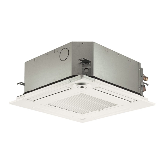
Indoor unit
[Model Name]
SLZ-M15FA2.TH
SLZ-M15FA2-ER.TH
SLZ-M15FA2-ET.TH
SLZ-M25FA2.TH
SLZ-M25FA2-ER.TH
SLZ-M25FA2-ET.TH
SLZ-M35FA2.TH
SLZ-M35FA2-ER.TH
SLZ-M35FA2-ET.TH
SLZ-M50FA2.TH
SLZ-M50FA2-ER.TH
SLZ-M50FA2-ET.TH
SLZ-M60FA2.TH
SLZ-M60FA2-ER.TH
SLZ-M60FA2-ET.TH
Model name
indication
TCH067.indd 1
TCH067.indd 1
[Service Ref.]
SLZ-M15FA2.TH
SLZ-M15FA2-ER.TH
SLZ-M15FA2-ET.TH
SLZ-M25FA2.TH
SLZ-M25FA2-ER.TH
SLZ-M25FA2-ET.TH
SLZ-M35FA2.TH
SLZ-M35FA2-ER.TH
SLZ-M35FA2-ET.TH
SLZ-M50FA2.TH
SLZ-M50FA2-ER.TH
SLZ-M50FA2-ET.TH
SLZ-M60FA2.TH
SLZ-M60FA2-ER.TH
SLZ-M60FA2-ET.TH
INDOOR UNIT
R32/R410A
CONTENTS
1. REFERENCE MANUAL ...................... 2
2. SAFETY PRECATION ......................... 2
3. PARTS NAMES AND FUNCTIONS ..... 9
4. SPECIFICATIONS ............................. 10
5. NOISE CRITERION CURVES ........... 10
6. OUTLINES AND DIMENSIONS ......... 12
7. WIRING DIAGRAM ............................ 14
8. REFRIGERANT SYSTEM DIAGRAM ..... 15
9. TROUBLESHOOTING ....................... 16
10. 4-WAY AIRFLOW SYSTEM ............... 29
11. DISASSEMBLY PROCEDURE .......... 31
PARTS CATALOG (TCB067)
September 2021
No. TCH067
29/9/2564 13:36:28
29/9/2564 13:36:28
Advertisement
Table of Contents

Related Manuals for Mitsubishi Electric SLZ Series


Summary of Contents for Mitsubishi Electric SLZ Series
-
Page 1: Table Of Contents
SPLIT-TYPE, HEAT PUMP AIR CONDITIONERS September 2021 No. TCH067 TECHNICAL & SERVICE MANUAL R32/R410A Indoor unit [Model Name] [Service Ref.] SLZ-M15FA2.TH SLZ-M15FA2.TH SLZ-M15FA2-ER.TH SLZ-M15FA2-ER.TH SLZ-M15FA2-ET.TH SLZ-M15FA2-ET.TH SLZ-M25FA2.TH SLZ-M25FA2.TH SLZ-M25FA2-ER.TH SLZ-M25FA2-ER.TH SLZ-M25FA2-ET.TH SLZ-M25FA2-ET.TH SLZ-M35FA2.TH SLZ-M35FA2.TH SLZ-M35FA2-ER.TH SLZ-M35FA2-ER.TH SLZ-M35FA2-ET.TH SLZ-M35FA2-ET.TH SLZ-M50FA2.TH SLZ-M50FA2.TH SLZ-M50FA2-ER.TH SLZ-M50FA2-ER.TH SLZ-M50FA2-ET.TH... -
Page 2: Reference Manual
REFERENCE MANUAL OUTDOOR UNIT’S SERVICE MANUAL Model Name Service Manual No. PUHZ-ZR100V(Y)KA3 OCH645D PUHZ-ZR125V(Y)KA3 OCB645C PUHZ-ZR140V(Y)KA3 SUZ-M25VAR2 SUZ-M35VAR2 OCH684D SUZ-M50VAR2 OCB684C SUZ-M60VAR2 PUZ-ZM35VKA2 OCH751 PUZ-ZM50VKA2 OCB751 PUZ-ZM60/71VHA2 PUZ-ZM100V(Y)KA2 OCH771 PUZ-ZM125V(Y)KA2 OCB771 PUZ-ZM140V(Y)KA2 SUZ-KA25VA6 SUZ-KA35VA6 TCH004B SUZ-KA50VA6 TCB004B SUZ-KA60VA6 OCH635A PUHZ-ZRP71VHA2 OCB635A SAFETY PRECAUTION MEANINGS OF SYMBOLS DISPLAYED ON THE UNIT... - Page 3 2-2. CAUTIONS RELATED TO NEW REFRIGERANT Cautions for units utilizing refrigerant R32/R410A Preparation before the repair service. Precautions during the repair service. • Prepare the proper tools. • Do not perform the work involving the electric parts • Prepare the proper protectors. with wet hands.
- Page 4 [1] Warning for service (1) Do not alter the unit. (2) For installation and relocation work, follow the instructions in the Installation Manual and use tools and pipe components specifically made for use with refrigerant specified in the outdoor unit installation manual. (3) Ask a dealer or an authorized technician to install, relocate and repair the unit.
- Page 5 [4] Cautions for unit using R32 refrigerant Basic work procedures are the same as those for conventional units using refrigerant R410A. However, pay careful attention to the following points. (1) Information on servicing (1-1) Checks on the Area Prior to beginning work on systems containing flammable refrigerants, safety checks are necessary to ensure that the risk of ignition is minimized.
- Page 6 (3) Repair to intrinsically Safe Components Do not apply any permanent inductive or capacitance loads to the circuit without ensuring that this will not exceed the permissible voltage and current permitted for the equipment in use. Intrinsically safe components are the only types that can be worked on while live in the presence of a flammable atmos- phere.
- Page 7 a) Become familiar with the equipment and its operation. b) Isolate system electrically. c) Before attempting the procedure, ensure that: • mechanical handling equipment is available, if required, for handling refrigerant cylinders; • all personal protective equipment is available and being used correctly; •...
- Page 8 Unit Electronic weighing scale [5] Service tools Use the below service tools as exclusive tools for R32/R410A refrigerant. Refer to the spec name plate on outdoor unit for the type of refrigerant being used. Tool name Specifications · Use the existing fitting specifications . (UNF1/2) Gauge manifold ·...
-
Page 9: Parts Names And Functions
PARTS NAMES AND FUNCTIONS 3-1. INDOOR UNIT Filter Removes dust and pollutants Horizontal Air Outlet from drawn in air. Sets horizontal airflow automatically during cooling or dehumidifying. Grille Auto Air Swing Vane Disperses airflow up and down and adjusts the angle of airflow direction. -
Page 10: Specifications
SPECIFICATIONS Indoor unit service ref. SLZ-M15FA2.TH SLZ-M25FA2.TH SLZ-M35FA2.TH SLZ-M50FA2.TH SLZ-M60FA2.TH SLZ-M15FA2-ER.TH SLZ-M25FA2-ER.TH SLZ-M35FA2-ER.TH SLZ-M50FA2-ER.TH SLZ-M60FA2-ER.TH SLZ-M15FA2-ET.TH SLZ-M25FA2-ET.TH SLZ-M35FA2-ET.TH SLZ-M50FA2-ET.TH SLZ-M60FA2-ET.TH Mode Cooling Heating Cooling Heating Cooling Heating Cooling Heating Cooling Heating Power supply (phase, cycle, voltage) Single phase 50 Hz, 230 V Input [kW] 0.02... - Page 11 <50Hz> <50Hz> SLZ-M35FA2.TH SLZ-M50FA2.TH NOTCH SPL(dB) LINE SPL(dB) LINE NOTCH High SLZ-M35FA2-ER.TH High SLZ-M50FA2-ER.TH Medium Medium SLZ-M35FA2-ET.TH SLZ-M50FA2-ET.TH NC-70 NC-70 NC-60 NC-60 NC-50 NC-50 NC-40 NC-40 NC-30 NC-30 APPROXIMATE APPROXIMATE THRESHOLD OF THRESHOLD OF HEARING FOR NC-20 HEARING FOR NC-20 CONTINUOUS CONTINUOUS NOISE...
-
Page 12: Outlines And Dimensions
OUTLINES AND DIMENSIONS SLZ-M15FA2.TH SLZ-M25FA2.TH SLZ-M35FA2.TH SLZ-M50FA2.TH SLZ-M60FA.2TH SLZ-M15FA2-ER.TH SLZ-M25FA2-ER.TH SLZ-M35FA2-ER.TH SLZ-M50FA2-ER.TH SLZ-M60FA2-ER.TH SLZ-M15FA2-ET.TH SLZ-M25FA2-ET.TH SLZ-M35FA2-ET.TH SLZ-M50FA2-ET.TH SLZ-M60FA2-ET.TH Unit: mm TCH067 TCH067.indd 12 TCH067.indd 12 29/9/2564 13:36:31 29/9/2564 13:36:31... - Page 13 WIRED REMOTE CONTROLLER WIRELESS REMOTE CONTROLLER Unit: mm PAR-SL101A-E PAR-41MAA (Option) (Option) 14.5 64.7 TCH067 TCH067.indd 13 TCH067.indd 13 29/9/2564 13:36:31 29/9/2564 13:36:31...
-
Page 14: Wiring Diagram
WIRING DIAGRAM SLZ-M15FA2.TH SLZ-M25FA2.TH SLZ-M35FA2.TH SLZ-M50FA2.TH SLZ-M60FA.2TH SLZ-M15FA2-ER.TH SLZ-M25FA2-ER.TH SLZ-M35FA2-ER.TH SLZ-M50FA2-ER.TH SLZ-M60FA2-ER.TH SLZ-M15FA2-ET.TH SLZ-M25FA2-ET.TH SLZ-M35FA2-ET.TH SLZ-M50FA2-ET.TH SLZ-M60FA2-ET.TH TCH067 TCH067.indd 14 TCH067.indd 14 29/9/2564 13:36:32 29/9/2564 13:36:32... -
Page 15: Refrigerant System Diagram
REFRIGERANT SYSTEM DIAGRAM SLZ-M15FA2.TH SLZ-M25FA2.TH SLZ-M35FA2.TH SLZ-M50FA2.TH SLZ-M60FA.2TH SLZ-M15FA2-ER.TH SLZ-M25FA2-ER.TH SLZ-M35FA2-ER.TH SLZ-M50FA2-ER.TH SLZ-M60FA2-ER.TH SLZ-M15FA2-ET.TH SLZ-M25FA2-ET.TH SLZ-M35FA2-ET.TH SLZ-M50FA2-ET.TH SLZ-M60FA2-ET.TH Strainer Heat exchanger Refrigerant GAS pipe connection (Flare) Condenser/evaporator temperature thermistor (TH5) Refrigerant flow in cooling Refrigerant flow in heating Refrigerant LIQUID pipe connection (Flare) Pipe temperature thermistor/liquid... -
Page 16: Troubleshooting
TROUBLESHOOTING 9-1. TROUBLESHOOTING <Check code displayed by self-diagnosis and actions to be taken for service (summary)> Present and past check codes are logged, and they can be displayed on the wired remote controller or controller board of out- door unit. Actions to be taken for service, which depends on whether or not the trouble is reoccurring in the field, are summa- rized in the table below. - Page 17 Refer to the following tables for details on the check codes. [Output pattern A] Beeper sounds Beep Beep Beep Beep Beep Beep Beep 1 st 2 nd 3 rd n th 1 st 2 nd OPERATION · · · Repeated INDICATOR lamp blinking pattern...
- Page 18 Notes: 1. If the beeper does not sound again after the initial 2 beeps to confirm the self-check start signal was received and the OPERATION INDICATOR lamp does not come on, there are no error records. 2. If the beeper sounds 3 times continuously “beep, beep, beep (0.4 + 0.4 + 0.4 seconds)” after the initial 2 beeps to confirm the self- check start signal was received, the specified refrigerant address is incorrect.
- Page 19 Note: Errors to be detected in outdoor unit, such as codes starting with F, U or E (excluding E0 to E7), are not covered in this document. Please refer to the outdoor unit's service manual 9-3. SELF-DIAGNOSIS ACTION TABLE for the details. Check code Abnormal point and detection method Countermeasure...
- Page 20 Check code Abnormal point and detection method Countermeasure Cause Freezing/overheating protection is (Cooling or drying mode) (Cooling or drying mode) operating 1 Clogged filter (reduced airflow) 1 Check clogging of the filter. Freezing protection (Cooling mode) Short cycle of air path Remove blockage.
- Page 21 Abnormal point and detection method Countermeasure Check code Cause Pipe temperature thermistor/Condenser /Evaporator (TH5) 1 The unit is in 3-minute resume protec- 1 Defective thermistor 1– Check resistance value of thermistor. tion mode if short/open of thermistor is characteristics For characteristics, refer to (P1). detected.
- Page 22 Abnormal point and detection method Countermeasure Check code Cause Remote controller transmission error(E3)/signal receiving error(E5) 1 2 remote controllers are set as 1 Set a remote controller to main, and the 1 Abnormal if remote controller could not other to sub. “main.”...
- Page 23 Check code Abnormal point and detection method Countermeasure Cause Forced compressor stop (due to water leakage abnormality) 1 When the intake temperature subtracted 1 Drain pump trouble 1 Check the drain pump. from liquid pipe temperature is less than −10°C, drain sensor detects whether it is 2 Drain defective 2 Please check whether water can be drained.
- Page 24 9-4. TROUBLESHOOTING OF PROBLEMS Note: Refer to the manual of outdoor unit for the detail of remote controller. Phenomena Cause Countermeasure (1) LED2 on indoor controller board • When LED1 on indoor controller board is also off. 1 Check the voltage of outdoor power 1 Power supply of rated voltage is not supplied to out- is off.
- Page 25 9-5. TEST POINT DIAGRAM 9-5-1. Indoor controller board SLZ-M15FA2.TH SLZ-M25FA2.TH SLZ-M35FA2.TH SLZ-M50FA2.TH SLZ-M60FA.2TH SLZ-M15FA2-ER.TH SLZ-M25FA2-ER.TH SLZ-M35FA2-ER.TH SLZ-M50FA2-ER.TH SLZ-M60FA2-ER.TH SLZ-M15FA2-ET.TH SLZ-M25FA2-ET.TH SLZ-M35FA2-ET.TH SLZ-M50FA2-ET.TH SLZ-M60FA2-ET.TH CN90 CN4Z LED2 Connect to the wireless i-see Sensor (Sensor) Vane motor (MV) Power supply remote controller board (CNB) 12 V pulse output (Wired remote controller) CN22...
- Page 26 9-6. FUNCTION OF DIP SWITCH Each function is controlled by the DIP switch and the jumper wire on the indoor controller board. ■ The black square ( ) indicates a switch position. Switch Functions Setting by the DIP switch Remarks Model Setting 1 2 3 4 5...
- Page 27 9-7. TROUBLE CRITERION OF MAIN PARTS SLZ-M15FA2.TH SLZ-M25FA2.TH SLZ-M35FA2.TH SLZ-M50FA2.TH SLZ-M60FA.2TH SLZ-M15FA2-ER.TH SLZ-M25FA2-ER.TH SLZ-M35FA2-ER.TH SLZ-M50FA2-ER.TH SLZ-M60FA2-ER.TH SLZ-M15FA2-ET.TH SLZ-M25FA2-ET.TH SLZ-M35FA2-ET.TH SLZ-M50FA2-ET.TH SLZ-M60FA2-ET.TH Parts name Check method and criterion Room temperature Measure the resistance with a tester. thermistor (TH1) (Parts temperature 10 to 30°C) Pipe temperature Abnormal Normal...
- Page 28 9-7-1. Thermistor Characteristic Graph < Thermistor for lower temperature > •Room temperature thermistor (TH1) •Pipe temperature thermistor/liquid (TH2) Thermistor for •Condenser/evaporator temperature lower temperature thermistor (TH5) Thermistor R =15 kΩ ± 3% Fixed number of B=3480 ± 2% Rt=15exp { 3480( 273+t 0˚C 15 kΩ...
-
Page 29: Way Airflow System
4-WAY AIRFLOW SYSTEM 10-1. FRESH AIR INTAKE (LOCATION FOR INSTALLATION) At the time of installation, use the duct holes (cut out) located at the positions shown in following diagram, as and when required. Fresh air intake Detail drawing of fresh air intake (mm) Burring hole Cutout hole... - Page 30 10-4. FIXING HORIZONTAL VANE Horizontal vane of each air outlet can be fixed according to the environment where it is installed. Setting procedure 1) Turn off a main power supply (Turn off a breaker). 2) Remove the vane motor connector in the direction of the arrow shown below with pressing the unlocking button as in the figure below.
-
Page 31: Disassembly Procedure
DISASSEMBLY PROCEDURE SLZ-M15FA2.TH SLZ-M25FA2.TH SLZ-M35FA2.TH SLZ-M50FA2.TH SLZ-M60FA.2TH SLZ-M15FA2-ER.TH SLZ-M25FA2-ER.TH SLZ-M35FA2-ER.TH SLZ-M50FA2-ER.TH SLZ-M60FA2-ER.TH SLZ-M15FA2-ET.TH SLZ-M25FA2-ET.TH SLZ-M35FA2-ET.TH SLZ-M50FA2-ET.TH SLZ-M60FA2-ET.TH Be careful when removing heavy parts. OPERATING PROCEDURE PHOTOS/FIGURES 1. Removing the air intake grille and air filter Figure 1 (1) Slide the knob of air intake grille to the direction of the arrow 1 to open the air intake grille. - Page 32 OPERATING PROCEDURE PHOTOS/FIGURES Photo 4 3. Removing the electrical parts Control box cover (1) Loosen the 2 screws on the control box cover. (2) Slide the control box cover as indicated by the arrow to remove. <Electrical parts in the control box> •...
- Page 33 OPERATING PROCEDURE PHOTOS/FIGURES 6. Removing the pipe temperature thermistor/liquid (TH2) Photo 8 Condenser / evaporator and condenser / evaporator temp. thermistor (TH5) Fan motor temp. thermistor (Th5) Band cable (1) Remove the panel. (Refer to procedure 2) (2) Remove the room temperature thermistor (TH1). (Refer to procedure 4) (3) Remove the drain pan.
- Page 34 OPERATING PROCEDURE PHOTOS/FIGURES 8. Removing the drain pump (DP) and float switch (FS) Photo 11 Clamp (1) Remove the panel. (Refer to procedure 2) (2) Remove the room temperature thermistor (TH1). (Refer Screw Inner cover to procedure 4) (3) Remove the control box cover. (Refer to procedure 3) (4) Remove the drain pan.
- Page 35 REMOTE CONTROLLER 13-1. REMOTE CONTROLLER FUNCTIONS <PAR-41MAA> Controller interface The functions of the function buttons change depending on the screen. Refer to the button function guide that appears at the bottom of the LCD for the functions they serve on a given screen. When the system is centrally controlled, the button function guide that corresponds to the locked button will not appear.
- Page 36 Display The main display can be displayed in two different modes: ˝Full˝ and ˝Basic˝. The initial setting is ˝Full˝. To switch to the ˝Basic˝ mode, change the setting on the Main display setting. (Refer to operation manual included with remote controller.) <Full mode>...
- Page 37 Menu structure Main menu Press the button. Move the cursor to the desired item with the buttons, and press the button. Operation Vane · 3D i-See · Vent. (Lossnay) High power Comfort Manual vane angle 3D i-See sensor Vertical air direction Horizontal air direction Timer menu Timer...
- Page 38 Continue from the previous page. Maintenance menu Error information Filter information Cleaning Auto descending panel Descending operation Descending adjustment Service menu Test run menu Test run Drain pump test run Maintenance information Collect model names and serial No. Model name input Serial No.
- Page 39 Main menu list Main Setting and display items Setting details menu Operation Vane · 3D i-See · Vent. Vane: Use to set the vertical air direction. (Vane.Vent. (Lossnay)) Louver: Use to set the horizontal air direction. 3D i-See sensor: This setting is available only for the air conditioners that support easy setting function of motion sensing air direction.
- Page 40 Main Setting and display items Setting details menu Initial Basic Main/Sub When connecting 2 remote controllers, one of them needs to be designated as setting setting a sub controller. Clock Use to set the current time. Daylight Set the daylight saving time. saving time Administrator The administrator password is required to make the settings for the following...
- Page 41 <PAR-SL97A-E> Controller interface Transmission area Transmission indicator Remote controller display Timer indicator *For explanation purposes, all of the items that appear in the display are shown. *All items are displayed when the Reset button is pressed. Operation areas ON/OFF button Temperature setting buttons Fan Speed button (Changes fan speed) Timer Off button...
- Page 42 <PAR-SL101A-E> Controller interface Transmission area Remote controller display Set Temperature buttons OFF/ON button Mode button (Changes operation mode) Fan Speed button (Changes fan speed) Airflow button (Changes up/ i-see button* down airflow direction) Timer ON button Menu button Timer OFF button SET/SEND button Weekly timer ON/OFF button* CANCEL button...
- Page 43 13-2. ERROR INFORMATION When an error occurs, the following screen will appear. Check the error status, stop the operation, and consult your dealer. 1. Check code, error unit, refrigerant address, date and time of occur- Error information rence, model name, and serial number will appear. Error code The model name and serial number will appear only if the informa- Error unit...
- Page 44 • Checking the error information Maintenance menu While no errors are occurring, page 2/2 of the error information can be Error information viewed by selecting ˝Error information˝ from the Maintenance menu. Filter information Errors cannot be reset from this screen. Cleaning Main menu: Cursor...
- Page 45 13-3. SERVICE MENU Maintenance password is required 1. Select ˝Service˝ from the Main menu, and press the [ ] button. Main Main menu *At the main display, the menu button and select ˝Service˝ to make Service the maintenance setting. 2. When the Service menu is selected, a window will appear asking for the pass- Service menu word.
- Page 46 13-4. TEST RUN 13-4-1. PAR-41MAA 1. Select ˝Service˝ from the Main menu, and press the [ ] button. Test run Input maintenance info. Settings Check Select ˝Test run˝ with the F1 or F2 button, and press the [ ] button. Others 2.
- Page 47 13-4-2. PAR-SL97A-E Measure an impedance between the power supply terminal block on the outdoor unit and ground with a 500 V Megger and check that it is equal to or greater than 1.0 MΩ. TEST RUN 1. Turn on the main power to the unit. TEST RUN 2.
- Page 48 13-5. FUNCTION SETTING 13-5-1. PAR-41MAA Settings menu 1. Select ˝Service˝ from the Main menu, and press the [ ] button. Function setting Rotation setting Select ˝Setting˝ from the Service menu, and press the [ ] button. Service menu: Select ˝Function setting˝, and press the [ ] button.
- Page 49 Pattern 2 Function setting Ref. address 4. Toggle through the pages with the F3 or F4 button. Grp. (1/8) Mode 1 Mode 2 Mode 3 5. Select the mode number with the F1 or F2 button, and then press the [ Mode 4 button.
- Page 50 13-5-2. PAR-SL97A-E Functions can be selected with the wireless remote controller. Function selection using wireless remote controller is available only for refriger- ant system with wireless function. Refrigerant address cannot be specified by the wireless remote controller. [Flow of function selection procedure] The flow of the function selection procedure is shown below.
- Page 51 13-5-3. PAR-SL101A-E 1. Going to the function select mode Press the button between of 5 seconds. (Start this operation from the status of remote controller display turned off.) [CHECK] is lit and ˝00˝ blinks. (Fig. 1) Press the button to set the ˝50˝. Direct the wireless remote controller toward the receiver of the indoor unit and press the button.
- Page 52 13-6. ROTATION SETTING Setting method of each function by wired remote controller Settings menu Function setting ■ PAR-41MAA Rotation setting 1. Stop operation Service menu: Select "Service" from the Main menu, and press the [ ] button. Cursor Select "Settings" with the F1 or F2 button, and press the [ ] button.
- Page 53 13-7. ERROR HISTORY 1. Select ˝Service˝ from the Main menu, and press the [ ] button. Test run Input maintenance info. Settings Check Others Select ˝Check˝ with the F1 or F2 button, and press the [ button. Select ˝Error history˝ with the F1 or F2 button, and press the [ ] button.
- Page 54 5. Preliminary error history Preliminary error hist. Select "Preliminary error hist." from the Error history menu, and press Error Unt# dd/mm/yy the [ ] button. 32 preliminary error history records will appear. Error history menu: Delete Page 4 records are shown per page, and the top record on the first page indi- cates the latest error record.
- Page 55 13-8. SELF-DIAGNOSIS 13-8-1. PAR-41MAA 1. Select ˝Service˝ from the Main menu, and press the [ ] button. Diagnosis Self check Select ˝Check˝ from the Service menu, Remote controller check and press the [ ] button. Service menu: Select ˝Diagnosis˝ from the Check menu, Cursor and press the [ ] button.
- Page 56 13-8-2. PAR-SL97A-E When a malfunction occurs to air conditioner, both indoor unit and outdoor unit will stop and operation lamp blinks to inform unusual stop. < Malfunction-diagnosis method at maintenance service> Refrigerant [Procedure] address display 1. Press the CHECK button twice. CHECK •...
- Page 57 13-9. REMOTE CONTROLLER CHECK If operations cannot be completed with the remote controller, diagnose the remote controller with this function. 1. Select ˝Service˝ from the Main menu, Diagnosis and press the [ ] button. Self check Remote controller check Select ˝Check˝ from the Service menu, and press the [ ] button.
- Page 58 13-10. SMOOTH MAINTENANCE 1. Select ˝Service˝ from the Main menu, and press the [ ] button. Check menu Error history Diagnosis Smooth maintenance Request code Select ˝Check˝ with the F1 or F2 button, and press the [ ] button. Service menu: Cursor Select ˝Smooth maintenance˝...
- Page 59 ■ Refrigerant address Single refrigerant system Multi refrigerant system (group control) In the case of single refrigerant system, the refrigerant address Up to 16 refrigerant systems (16 outdoor units) can be con- is ˝00˝ and no operation is required. nected as a group by 1 remote controller. To check or set the Simultaneous twin, triple units belong to this category refrigerant addresses.
- Page 60 HEAD OFFICE : TOKYO BUILDING, 2-7-3, MARUNOUCHI, CHIYODA-KU, TOKYO 100-8310, JAPAN MITSUBISHI ELECTRIC CONSUMER PRODUCTS (THAILAND) CO., LTD. 700/406 MOO 7, TAMBON DON HUA ROH, AMPHUR MUANG, CHONBURI 20000 THAILAND Published: Sep. 2021. No. TCH067 Specifications are subject to change without notice.