Advertisement
Quick Links
Air Conditioners
SLZ-M15, M25, M35, M50, M60FA
INSTALLATION MANUAL
INSTALLATIONSHANDBUCH
MANUEL D'INSTALLATION
INSTALLATIEHANDLEIDING
MANUAL DE INSTALACIÓN
MANUALE DI INSTALLAZIONE
MANUAL DE INSTALAÇÃO
INSTALLATIONSMANUAL
INSTALLATIONSMANUAL
FOR INSTALLER
FÜR INSTALLATEURE
VOOR DE INSTALLATEUR
TIL INSTALLATØREN
FÖR INSTALLATÖREN
FOR MONTØR
DLA INSTALATORA
English
-
Deutsch
-
Français
Nederlands
-
Español
Italiano
Dansk
Svenska
Türkçe
Norsk
Advertisement

Related Manuals for Mitsubishi Electric Mr.Slim SLZ-M15


Summary of Contents for Mitsubishi Electric Mr.Slim SLZ-M15
- Page 1 Air Conditioners SLZ-M15, M25, M35, M50, M60FA INSTALLATION MANUAL FOR INSTALLER English INSTALLATIONSHANDBUCH FÜR INSTALLATEURE Deutsch MANUEL D’INSTALLATION Français INSTALLATIEHANDLEIDING VOOR DE INSTALLATEUR Nederlands MANUAL DE INSTALACIÓN Español MANUALE DI INSTALLAZIONE Italiano MANUAL DE INSTALAÇÃO INSTALLATIONSMANUAL TIL INSTALLATØREN Dansk INSTALLATIONSMANUAL FÖR INSTALLATÖREN Svenska Türkçe...
- Page 2 Contents 1. Safety precautions ..................2 7. Electrical work ....................9 2. Selecting the installation location ..............3 8. Test run ......................16 3. Installation diagram ..................4 9. System control ..................... 18 4. Installing the indoor unit ................. 4 10.
-
Page 3: Safety Precautions
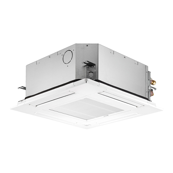
1. Safety precautions 2.2. wireless remote controller may not be received. controller are surely received by the indoor unit from that position (‘beep’ or ‘beep- or wall and set the wireless remote controller. - Page 4 Ceiling Grille Obstacle Min. 1000 mm If setting the maintenance space for , be sure to leave is a minimum of 700 mm. Refer to the outdoor unit installation manual. The indoor unit should be supplied with the following accessories. Accessory name Q’ty Installation template...
- Page 5 120° 10 tapping screws which should be prepared locally. wrap the duct in a heat insulate to avoid causing dew drop on the wall. 3-Tapping screw hole ø73.4 cutout hole 3-ø5 hole Detail drawing of fresh air intake Indoor unit Insulation Ceiling surface Unit...
- Page 6 Indoor unit Outdoor unit ø6.35 Outside diameter Min. wall Insulation Insulation Model Pipe SLZ-M15, M25, M35: ø9.52 thickness thickness material inch SLZ-M50: ø12.7 SLZ-M15 For liquid 6.35 0.8 mm 8 mm SLZ-M60: ø15.88 SLZ-M25 Heat resist- For gas 9.52 0.8 mm 8 mm SLZ-M35 ing foam...
- Page 7 45°± 2° Smooth all around Inside is shining without any scratches Cracked Even length all around Uneven Too much Bad examples Tilted Drain pipe Ceiling Grille Main unit Dimension Model SLZ-M15 SLZ-M25 63 mm 72 mm SLZ-M35 SLZ-M50 63 mm 78 mm SLZ-M60 completed.
- Page 8 Max. 20 m 1.5–2 m downward slope. Correct piping Support metal Air bleeder Raised Odor trap Grouped piping Make it as large as possible Indoor unit Max. 150 mm Up to 850 mm 5. Insulate the drain port with insulating material, then secure the material with a 30 30 Main unit Insulating material...
- Page 9 The following connection patterns are available. The outdoor unit power supply patterns vary on models. 1:1 System A Outdoor unit power supply B Earth leakage breaker D Outdoor unit F Remote controller G Indoor unit A Outdoor unit power supply B Earth leakage breaker D Outdoor unit F Remote controller...
- Page 10 1. Loosen the two screws securing the electric component cover, and then slide and remove the cover. 2. Route the wires along the wiring routes and through the wire inlets in the electric component box. cable to the terminal block. 4.
- Page 11 Before installing the grille, connect the junction wires included with the grille acces- sories and place them in the connector box. Remove the two screws securing the wire cover of the main unit, and then open the cover. Route the wires of the i-See sensor and signal receiver through the wire inlets in the electric component box as shown in the diagram and around the bushings on secure the grille junction wire and the wires of the i-See sensor and signal receiver with the clamp.
- Page 12 Refer to the installation manual that comes with each remote controller for details. If two remote controllers are connected, set one to “Main” and the other to “Sub”. For setting procedures, refer to “Function selection of remote controller” in the operation manual for the indoor unit.
- Page 13 Service menu Function setting Test run Ref. address Input maintenance info. Unit No. Grp./1/2/3/4/All Function setting Select “Service” from the Main menu, and press the [SELECT] button. Check Self check button. Main menu: Monitor: Cursor Cursor Address [F1] through [F4] buttons, and then press the [SELECT] rent setting.
- Page 14 Select unit number 00 [table 1] Mode Settings Mode no. Setting no. Initial setting setting Power failure automatic recovery Not available Available Indoor temperature detecting Indoor unit operating average Set by indoor unit’s remote controller Remote controller’s internal sensor Mode Settings Mode no.
- Page 15 The current vane setting will appear. Manual vane angle Select the desired outlets from 1 through 4 with the [F1] or [F2] button. Select: Outlet Angle Select the desired setting. No setting Step 1 Step 2 Step 3 Step 4 Step 5 Manual vane angle Draft...
- Page 16 Step 1 board uses a digital display, [- ] and [ -] will be displayed alternately every second. If the operations do not function correctly after the procedures in step 2 and thereafter are performed, the following causes should be considered and eliminated if they are found.
- Page 17 Note: If an error is displayed on the remote controller, see the table below. [Output pattern A] Errors detected by indoor unit controller Symptom Remark Check code INDICATOR lamp blinks (Num- Intake sensor error E6, E7 Drain pump error Forced compressor error Communication error between indoor and outdoor units Pipe temperature error Remote controller signal receiving error...
- Page 18 Turn on the power to the unit at least 12 hours before the test run. Press the Press the button. Press the button to activate cool mode, then check whether cool air is blown out from the unit. Press the button to activate heat mode, then check whether warm air is blown out from the unit.
- Page 19 relative to the ceiling. If the unit is not properly positioned in the ceiling, there may rectly. 576 - 610 576 - 610 to adhere to this range. Main unit Ceiling Ceiling opening dimensions to open the intake grille. * Do not unlatch the hook for the intake grille. from the grille as indicated by the arrow Intake grille Grille...
- Page 20 Remove the one screw securing the connector box cover, and then open the cover. Securely connect the junction wire connector of the vane motor and the panel vane There are two vane motor connectors: one blue connector and one orange con- nector.
- Page 21 The vanes of the unit can be set and locked in on up or down orientation depending upon the environment of use. performed using the remote controller. In addition, the actual position of the vanes may differ from the position indicated on the remote controller. Turn off the main power switch.